Journal of Software Engineering and Applications, 2012, 5, 659-663
http://dx.doi.org/10.4236/jsea.2012.59077 Published Online September 2012 (http://www.SciRP.org/journal/jsea)
659
Global Minimization of Vertex Height Differences for
Freeform Architectural Design*
Simon Kulovec, Leon Kos, Jože Duhovnik
Faculty of Mechanical Engineering, University of Ljubljana, Ljubljana, Slovenia.
Email: simon.kulovec@lecad.si
Received June 15th, 2012; revised July 20th, 2012; accepted August 3rd, 2012
ABSTRACT
Architectural design is leading us in the direction of structures with free and irregular forms. As a consequence of this
the connection between the design’s intent and its fabrication represents a challenge when creating a support structure
that is geometrically viable and which needs to possess certain aesthetic, fabricational, thermal and strength require-
ments. To ensure the contacts of the edges of the neighboring insulation panels along their thicknesses, the edges must
be cut at different angles, which causes differences in the vertex heights and, furthermore, differences in the positions of
the inner metal sheets of the insulation panels. The main goal of the presented research is the development of a
post-optimization procedure, by which the minimum joint-height differences will be achieved for all the joints, taking
into account all the free-form surfaces of the individual architectural design. To compensate for the residual height dif-
ferences the use of spacers of different thicknesses is proposed. The paper considers the global minimization of the
joint-height differences for a sample free-form architectural design that is meshed with a quad-dominant mesh.
Keywords: Planar Mesh; Support Structure; Post-Optimization; Height-Difference Function
1. Introduction
In the physical realization of a project the arbitrary
shapes designed by the architect must satisfy a number of
requirements that limit the possible realizable solutions
for the final “free forms”. Those are frequently used in
“sculptured” designs, like museums and towers that are
intended to be city landmarks. Such designs seek their
representation through shape, while applying cost-effec-
tive materials and making use of the whole of the avail-
able area.
The freeform surfaces of the structures can be de-
scribed by different types of meshes providing the plana-
rity of each of the mesh surface elements, i.e., the faces.
The existing freeform structures mainly consist of train-
gular meshes, where the condition of planarity is satisfied
automatically. We chose to use quadrilateral meshes [1]
(Figure 1), because they are cost effective, but also geo-
metrically complex. The condition of planarity is satis-
fied by an optimization algorithm based on Sequential
Quadratic Optimization [2].
Freeform façades consist of relatively thick, planar
(Figure 2), panel elements and of a corresponding sup-
port structure. The outer surfaces of the panel elements
coincide with the mesh faces (Figure 3). To ensure the
contact of the edges (Figure 3) of the neighboring panel
elements along their thicknesses, their edges must be cut
at different angles, which causes differences in the edge
heights and furthermore differences in the positions of
the inner metal sheets of the insulation panels.
In common support structures (Figure 4) where the
beams have the same height, the position of the beams
must compensate for the above-mentioned difference in
the positions of the outer metal sheets. For this reason
relatively large joint-height differences (Figures 5-
7) are necessary.
,
Δij
h
The differences in the positions of the beams ensure a
Figure 1. Double-curved freeform quad-dominant mesh.
*Post-optimization of height differences of Freeform Structures.
Copyright © 2012 SciRes. JSEA
Global Minimization of Vertex Height Differences for Freeform Architectural Design
660
Figure 2. Planar optimized mesh.
Figure 3. Mesh elements: vertex, edge and face.
Figure 4. CAD model of a support structure of planar mesh
structure.
constant distance between the outer metal sheet and the
beams of the structure. Producing, as a result, the differ-
ent vertex height distances (Figure 6).
,ij
The aim of this research is to develop a post-optimi-
zation procedure by which the minimum joint-height
differences ,,;max,;min
can be achieved for
all the joints, taking into account all the faces of the con-
sidered free-form architectural design. It should be pointed
out that the angles
h
Δij ijij
hh h
,1i
and ,2i
in all the joints are
already optimized [3,4] (Figures 6 and 7) and therefore
not subject to change.
Freeform structures require planarity for each closure
metal panel (insulation panel element) [5-7]. Planarity is
necessary for the building of the structure, particularly in
cases when the structure is covered with non-deformable
elements (e.g., glass). We are trying to make planar ele-
ments for the selected structure, while still keeping the
Figure 5. Geometry of the cylinder-beam intersection prob-
lem.
Figure 6. Initial vertex cross-section with equal spacer thick-
ness (h2 + di,2).
Figure 7. Post-optimized vertex cross-section with variable
spacer thickness (Δhi,z < Δhi,2 di,z < di,2).
Copyright © 2012 SciRes. JSEA
Global Minimization of Vertex Height Differences for Freeform Architectural Design 661
original outside form of the structure, as designed by the
architect. Triangular mesh elements do not require pla-
narization because their geometry is always planar. The
planarity of an element in a selected mesh should be
executed to the level that still allows the assembly of
closure elements.
Problem Formulation
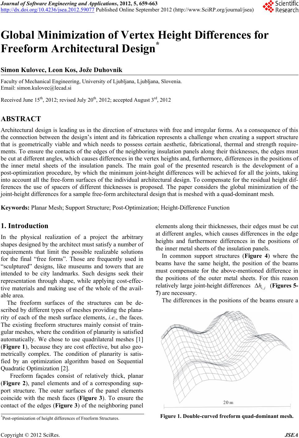
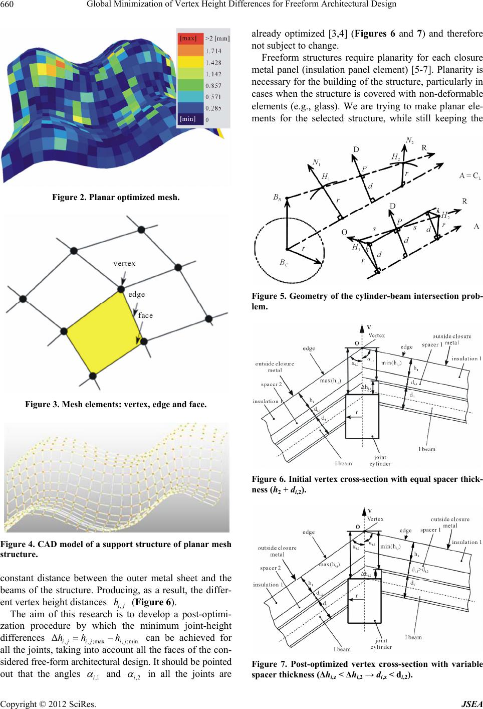
Figure 4 shows a CAD model, designed according to
planar and conical pre-optimized mesh. Figure 4 shows
the support structure only; composed of joint cylinders
and I beams. In every single joint cylinder (or joint box
[8]) is positioned according to a maximum vertex height
distance (,;maxij ). Therefore the top flange of the corre-
sponding I beam is leveled with the top edge of the joint
cylinder. All the other I beams, having smaller vertex
height distances, must be positioned higher, producing
additional internal loading in the joint cylinder and joint
cylinder-beam connection problems. The idea is to pro-
vide minimal possible joint height differences (,),
between top flange of the I beams in every single joint
cylinder, which significantly reduces additional forces
and moments in a joint cylinder (Figure 7). An post-
optimization algorithm was created to do the task for all
the joints in the structure. In chapter 4, a graphical analy-
sis of joint height differences is made for the entire mesh
of the sample free form structure. Minimization of these
differences in particular joint significantly reduces addi-
tional forces and moments in a joint cylinders.
h
Δij
h
2. Related Work
Not many papers cover our ideas presented in the
introduction. Multi-layer architecture, including planar
and conical meshes was discussed by Pottmann et al. [2,
5,9,10]. Although visually appealing P-hex meshes that
were also extended to meshes with parallel edges. P-hex
geometry inherits similar problems with a physical rea-
lization of vertex. The elimination of edge offset dif-
ferences can be achieved with Koebe polyhedra [11], but
this brings very restrictive geometry, which cannot
approximate arbitrary shapes. Still this is a promising
approach for glass structures with no closure layer
provided. Such surfaces can also be part of the freeform
structure that can be included in mesh optimization as a
rigid body. Pottmann et al. [10] also suggest to appro-
ximate beam offsets with fairness functional during
vertex perturbation. In their optimization they neglect the
physical realization of the vertex junction and concen-
trate on optimization to achieve an approximately con-
stant offset from a theoretical point of view. So far, we
are unaware of any architectural project that should use
the present geometry processing ideas, as it seems that
solutions need to be solved in detail in CAD (Figure 4)
before the realization is possible. In addition, a stress
analysis of such structure is required, which is not a
trivial task as adequate stucture computations are yet to
be determined.
3. Post-Optimization Method
3.1. The Joint Connection Differencesat Cylinder
In this section we briefly present the geometric algorithm
to locate the intersection points between a ray and a
cylinder following the Cychosz and Waggenspack [12]
algorithm.
We are only interested in the intersection point in
H
between the vertex cylinder and the beam. Connecting
height (
Figure 5) from vertex origin and beam-
cylinder intersection in
do
H
is calculated by projecting
vector in
H
o to vertex normal (see Figure 6). After
some algebra calculations we finally obtain
v

in
in in
H
dH H


vo
ovo (1)
Beam offset distance d can be regarded as a function
of many parameters, face normals, inclination and di
hedral angles. This function is obviously nonlinear and
so is the post-optimization procedure that generally mini-
mizes differences between each beam d in each vertex of
the structure. Solving such global post-optimization
problem can easily lead to local optimums. Especially
when structures are large. Many algorithms from com-
putational geometry try to avoid such situations by
defining local operators rather than solving the problem
globally. In this paper we follow such ideas by intro-
ducing two competitive algorithms with local impact and
compare their results.
3.2. Vertex Element Differences
In order to generate a CAD model, it is necessary to
specify the points where the support structures and the
joint elements are positioned. The beams are displaced at
the fixing points in the joint cylinder. The calculation of
the beam positions, displaced from the reference points,
is shown below.
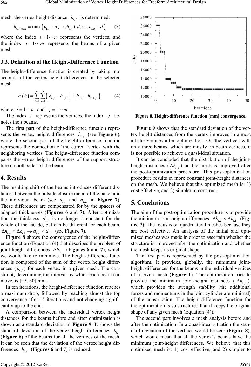
Figure 6 shows a cross-section of the cylindrical joint,
beams with insulation, spacers and outside closure metal.
The outside closure sheet normals 1 and 2 are
joined at the vertex reference point (
Figure 6).
n n
o
,1ij e
hh r

1
1
e
e
nn er
nn
(2)
where
12
12
enn
nnn and

e
rr
e
e
en
en
.
Vertex positioning. For each vertex of the selected
i
Copyright © 2012 SciRes. JSEA
Global Minimization of Vertex Height Differences for Freeform Architectural Design
662
mesh, the vertex height distance is determined:
,ij
h
1,i
d

, ;max1,11,
max, ,, ,
ij n
hhhdhd
n
(3)
where the index represents the vertices, and
the index represents the beams of a given
mesh.
1i
m1j
3.3. Definition of the Height-Difference Function
The height-difference function is created by taking into
account all the vertex height differences in the selected
mesh.


,,, 1,
11
nm
ijijiji j
ij
Fhh hh h



n
1 (4)
where and .
1i
i1jm
The index represents the vertices; the index de-
notes the I beams.
j
The first part of the height-difference function repre-
sents the vertex height differences ,ij
(see Figure 6),
while the second part of the height-difference function
represents the connection of the current vertex with the
neighboring vertices. The height-difference function com-
pares the vertex height differences of the support struc-
ture on both sides of the beam.
h
4. Results
The resulting shift of the beams introduces different dis-
tances between the outside closure metal of the panel and
the individual beam (see ,1i and ,2i in Figure 7).
These differences are compensated for by the spacers of
adapted thicknesses (Figures 6 and 7). After optimiza-
tion the thickness ,1i is no longer a constant for the
whole of the façade, but can be different for each beam,
(see
Figure 7).
d d
d
i
d
,2,1,2 ,1i
Figure 8 shows the convergence of the height-differ-
ence function (Equation (4) that describes the problem of
joint-height differences , (Figures 6 and 7), which
we would like to minimize. The height-difference func-
tion is composed of the sum of the vertex height differ-
ences (,ij
) for each vertex in a given mesh. The con-
straint, determining the interval by which each beam can
move, is [5, 30] mm.
ΔΔ
ii
hh d
Δij
h
h
In ten iterations, the height-difference function reaches
a maximum drop, followed by reaching almost the top
convergence after 15 iterations and not changing signifi-
cantly up to the end.
A comparison between the individual vertex height
distances for the beams before and after optimization is
shown as a standard deviation in Figure 9. It shows the
standard deviation of the vertex height differences ,ij
(Figure 6) of the beams for all the vertices of the mesh.
It can be seen that the deviation of the vertex height dif-
ferences (
Figures 6 and 7) is reduced.
h
,ij
h
Figure 8. Height-difference function [mm] convergence.
Figure 9 shows that the standard deviation of the ver-
tex height distances from the vertex improves in almost
all the vertices after optimization. On the vertices with
only three beams, which are mostly on beam vertices, it
is not possible to achieve a quasi-ideal situation.
It can be concluded that the distribution of the joint-
height distances (,
Δij) on the mesh is improved after
the post-optimization procedure. This post-optimization
procedure results in more constant joint-height distances
on the mesh. We believe that this optimized mesh is: 1)
cost effective, and 2) simpler to construct.
h
5. Conclusions
The aim of the post-optimization procedure is to provide
the minimum joint-height differences ,2,1i
(Fig-
ure 7). The focus is on quadrilateral meshes because they
are cost effective. An analysis of the initial and opti-
mized meshes was made in order to ascertain whether the
structure is improved after the optimization and whether
the mesh keeps its original shape.
ΔΔ
i
hh
The first part is represented by the post-optimization
algorithm. It provides, globally, the minimum joint-
height differences for the beams in the individual vertices
of a given mesh (Figure 1). The optimization tries to
provide the minimum joint-height distances (,),
which provides the strength stability (the additional
forces and momentums in the joint cylinder are minimal)
of the construction. The height-difference function for
the optimization is so structured that it keeps the original
shape of any given mesh (Equation (4)).
Δij
h
The second part involves a mesh analysis before and
after the optimization. In a quasi-ideal situation the stan-
dard deviation of the vertices would be zero (Figure 8),
which would mean that all the vertex’s beams have the
minimum joint-height differences. We believe that this
optimized mesh is: 1) cost effective, and 2) simpler to
Copyright © 2012 SciRes. JSEA
Global Minimization of Vertex Height Differences for Freeform Architectural Design
Copyright © 2012 SciRes. JSEA
663
0
5
10
15
20
25
30
35
050100 150 200 250 300 350 400 450 500 550
σ[mm]
Vertex no.
Figure 9. Standard deviation of vertex height distances before and after post-optimization.
[6] K. Madsen, H. B. Nielsen and O. Tingleff, “Optimization
with Constraints,” 2nd Edition, 2004.
construct.
[7] O. Schenk and K. Gärtner, “Solvingunsymmetric Sparse
Systems of Linear Equations with Pardiso,” Journal of
Future Generation Computer Systems, Vol. 20, No. 4,
2004, pp. 475-487. doi:10.1016/j.future.2003.07.011
REFERENCES
[1] S. Kulovec, L. Kos and J. Duhovnik, “Mesh Smoothing
with Global Optimization under Constraints,” Strojniški-
vestnik Journal of Mechanical Engineering, Vol. 57, No.
7, 2010, pp. 555-567.
[8] J. Duhovnik, S. Kulovec and L. Kos, “Multiple Vertex
Joint Adapter,” Patent No. p201000325, 2010.
[2] H. Pottmann and J. Wallner, “The Focal Geometry of
Circular and Conical Meshes,” Advances in Computational
Mathematics, Vol. 29, No. 3, 2008, pp. 249-268.
doi:10.1007/s10444-007-9045-4
[9] H. Pottman, A. Asperl, M. Hofer and A. Kilian, Eds.,
“Arhitectural Geometry,” Bentley Institute Press, Exton,
2008.
[10] H. Pottmann, Y. Liu, J. Wallner, A. Bobenko and W.
Wang, “Geometry of Multi-Layer Freeform Structures for
Architecture,” ACM Transactions on Graphics, Vol. 26,
No. 3, 2007, Article No. 65.
doi:10.1145/1276377.1276458
[3] L. Kos, S. Kulovec, V. Zaletelj and J. Duhovnik, “Struc-
ture Generation for Free-Form Architectural Design,”
Advanced Engineering, Vol. 3, No. 2, 2009, pp. 187-194.
[4] L. Kos, S. Kulovec and J. Duhovnik, “Support Structure
Optimization for Freeform Architectural Design,” TMCE
2010, University of Technology, Delft, 2010, pp. 829-
840.
[11] A. I. Bobenko, T. Hoffmann and B. A. Springhorn,
“Minimal Surfaces from Cicle Patterns: Geometry from
Combinatorics,” Annals of Mathematics, Vol. 164, No. 1,
2006, pp. 231-264. doi:10.4007/annals.2006.164.231
[5] W. Wang, Y. Liu, D. Yan, B. Chan, R. Ling and F. Sun,
“Hexagonal Meshes with Planar Faces,” Tech. Rep. TR-
2008-13, Department of Computer Science, The Univer-
sity of Hong Kong, Hong Kong, 2008.
[12] J. Cychosz and W. Waggenspack Jr., “Intersecting a Ray
with a Cylinder,” Academic Press, London, Vol. 2, 1994,
pp. 353-365.