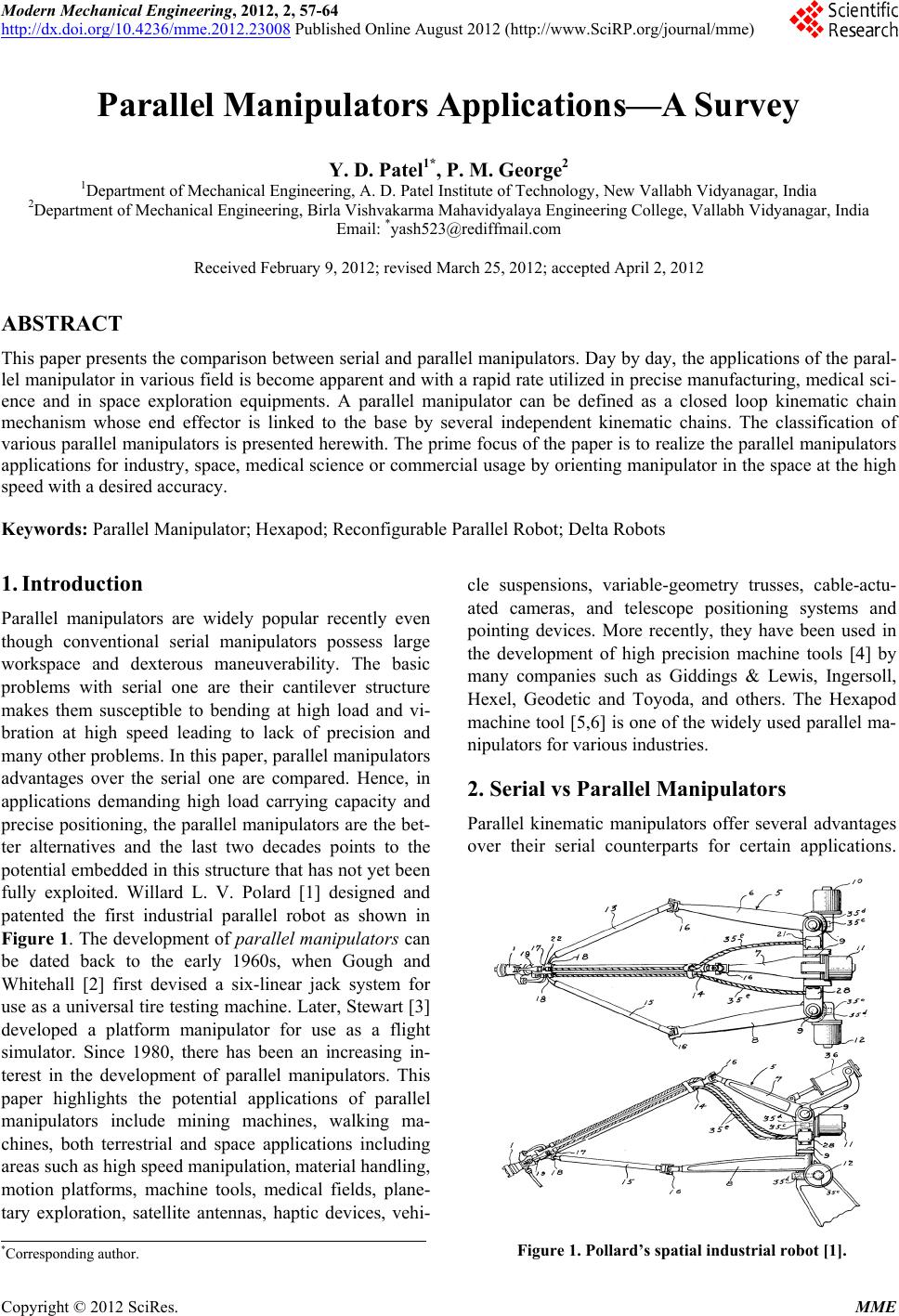
 Modern Mechanical Engineering, 2012, 2, 57-64 http://dx.doi.org/10.4236/mme.2012.23008 Published Online August 2012 (http://www.SciRP.org/journal/mme) Parallel Manipulators Applications—A Survey Y. D. Patel1*, P. M. George2 1Department of Mechanical Engineering, A. D. Patel Institute of Technology, New Vallabh Vidyanagar, India 2Department of Mechanical Engineering, Birla Vishvakarma Mahavidyalaya Engineering College, Vallabh Vidyanagar, India Email: *yash523@rediffmail.com Received February 9, 2012; revised March 25, 2012; accepted April 2, 2012 ABSTRACT This paper presents the comparison between serial and parallel manipulators. Day by day, the applications of the paral- lel manipulator in various field is become apparent and with a rapid rate utilized in precise manufacturing, medical sci- ence and in space exploration equipments. A parallel manipulator can be defined as a closed loop kinematic chain mechanism whose end effector is linked to the base by several independent kinematic chains. The classification of various parallel manipulators is presented herewith. The prime focus of the paper is to realize the parallel manipulators applications for industry, space, medical science or commercial usage by orienting manipulator in the space at the high speed with a desired accuracy. Keywords: Parallel Manipulator; Hexapod; Reconfigurable Parallel Robot; Delta Robots 1. Introduction Parallel manipulators are widely popular recently even though conventional serial manipulators possess large workspace and dexterous maneuverability. The basic problems with serial one are their cantilever structure makes them susceptible to bending at high load and vi- bration at high speed leading to lack of precision and many other problems. In this paper, parallel manipulators advantages over the serial one are compared. Hence, in applications demanding high load carrying capacity and precise positioning, the parallel manipulators are the bet- ter alternatives and the last two decades points to the potential embedded in this structure that has not yet been fully exploited. Willard L. V. Polard [1] designed and patented the first industrial parallel robot as shown in Figure 1. The development of parallel manipulators can be dated back to the early 1960s, when Gough and Whitehall [2] first devised a six-linear jack system for use as a universal tire testing machine. Later, Stewart [3] developed a platform manipulator for use as a flight simulator. Since 1980, there has been an increasing in- terest in the development of parallel manipulators. This paper highlights the potential applications of parallel manipulators include mining machines, walking ma- chines, both terrestrial and space applications including areas such as high speed manipulation, material handling, motion platforms, machine tools, medical fields, plane- tary exploration, satellite antennas, haptic devices, vehi- cle suspensions, variable-geometry trusses, cable-actu- ated cameras, and telescope positioning systems and pointing devices. More recently, they have been used in the development of high precision machine tools [4] by many companies such as Giddings & Lewis, Ingersoll, Hexel, Geodetic and Toyoda, and others. The Hexapod machine tool [5,6] is one of the widely used parallel ma- nipulators for various industries. 2. Serial vs Parallel Manipulators Parallel kinematic manipulators offer several advantages over their serial counterparts for certain applications. Figure 1. Pollard’s spatial industrial robot [1]. *Corresponding author. C opyright © 2012 SciRes. MME 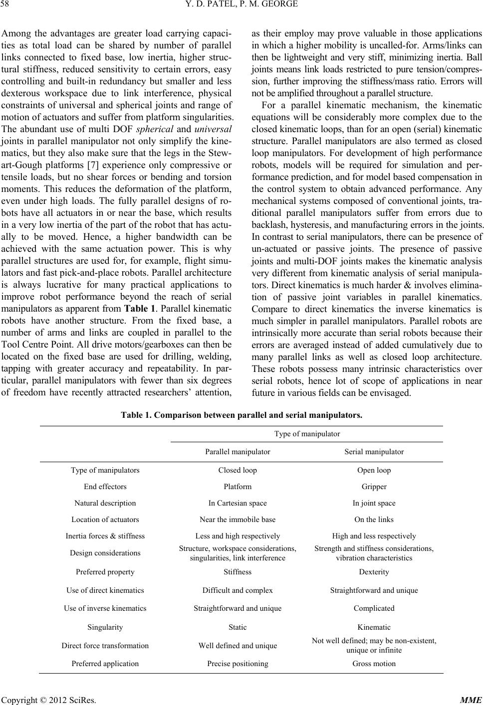 Y. D. PATEL, P. M. GEORGE 58 Among the advantages are greater load carrying capaci- ties as total load can be shared by number of parallel links connected to fixed base, low inertia, higher struc- tural stiffness, reduced sensitivity to certain errors, easy controlling and built-in redundancy but smaller and less dexterous workspace due to link interference, physical constraints of universal and spherical joints and range of motion of actuators and suffer from platform singularities. The abundant use of multi DOF spherical and universal joints in parallel manipulator not only simplify the kine- matics, but they also make sure that the legs in the Stew- art-Gough platforms [7] experience only compressive or tensile loads, but no shear forces or bending and torsion moments. This reduces the deformation of the platform, even under high loads. The fully parallel designs of ro- bots have all actuators in or near the base, which results in a very low inertia of the part of the robot that has actu- ally to be moved. Hence, a higher bandwidth can be achieved with the same actuation power. This is why parallel structures are used for, for example, flight simu- lators and fast pick-and-place robots. Parallel architecture is always lucrative for many practical applications to improve robot performance beyond the reach of serial manipulators as apparent from Table 1. Parallel kinematic robots have another structure. From the fixed base, a number of arms and links are coupled in parallel to the Tool Centre Point. All drive motors/gearboxes can then be located on the fixed base are used for drilling, welding, tapping with greater accuracy and repeatability. In par- ticular, parallel manipulators with fewer than six degrees of freedom have recently attracted researchers’ attention, as their employ may prove valuable in those applications in which a higher mobility is uncalled-for. Arms/links can then be lightweight and very stiff, minimizing inertia. Ball joints means link loads restricted to pure tension/compres- sion, further improving the stiffness/mass ratio. Errors will not be amplified throughout a parallel structure. For a parallel kinematic mechanism, the kinematic equations will be considerably more complex due to the closed kinematic loops, than for an open (serial) kinematic structure. Parallel manipulators are also termed as closed loop manipulators. For development of high performance robots, models will be required for simulation and per- formance prediction, and for model based compensation in the control system to obtain advanced performance. Any mechanical systems composed of conventional joints, tra- ditional parallel manipulators suffer from errors due to backlash, hysteresis, and manufacturing errors in the joints. In contrast to serial manipulators, there can be presence of un-actuated or passive joints. The presence of passive joints and multi-DOF joints makes the kinematic analysis very different from kinematic analysis of serial manipula- tors. Direct kinematics is much harder & involves elimina- tion of passive joint variables in parallel kinematics. Compare to direct kinematics the inverse kinematics is much simpler in parallel manipulators. Parallel robots are intrinsically more accurate than serial robots because their errors are averaged instead of added cumulatively due to many parallel links as well as closed loop architecture. These robots possess many intrinsic characteristics over serial robots, hence lot of scope of applications in near future in various fields can be envisaged. Table 1. Comparison between parallel and serial manipulators. Type of manipulator Parallel manipulator Serial manipulator Type of manipulators Closed loop Open loop End effectors Platform Gripper Natural description In Cartesian space In joint space Location of actuators Near the immobile base On the links Inertia forces & stiffness Less and high respectively High and less respectively Design considerations Structure, workspace considerations, singularities, link interference Strength and stiffness considerations, vibration characteristics Preferred property Stiffness Dexterity Use of direct kinematics Difficult and complex Straightforward and unique Use of inverse kinematics Straightforward and unique Complicated Singularity Static Kinematic Direct force transformation Well defined and unique Not well defined; may be non-existent, unique or infinite Preferred application Precise positioning Gross motion Copyright © 2012 SciRes. MME 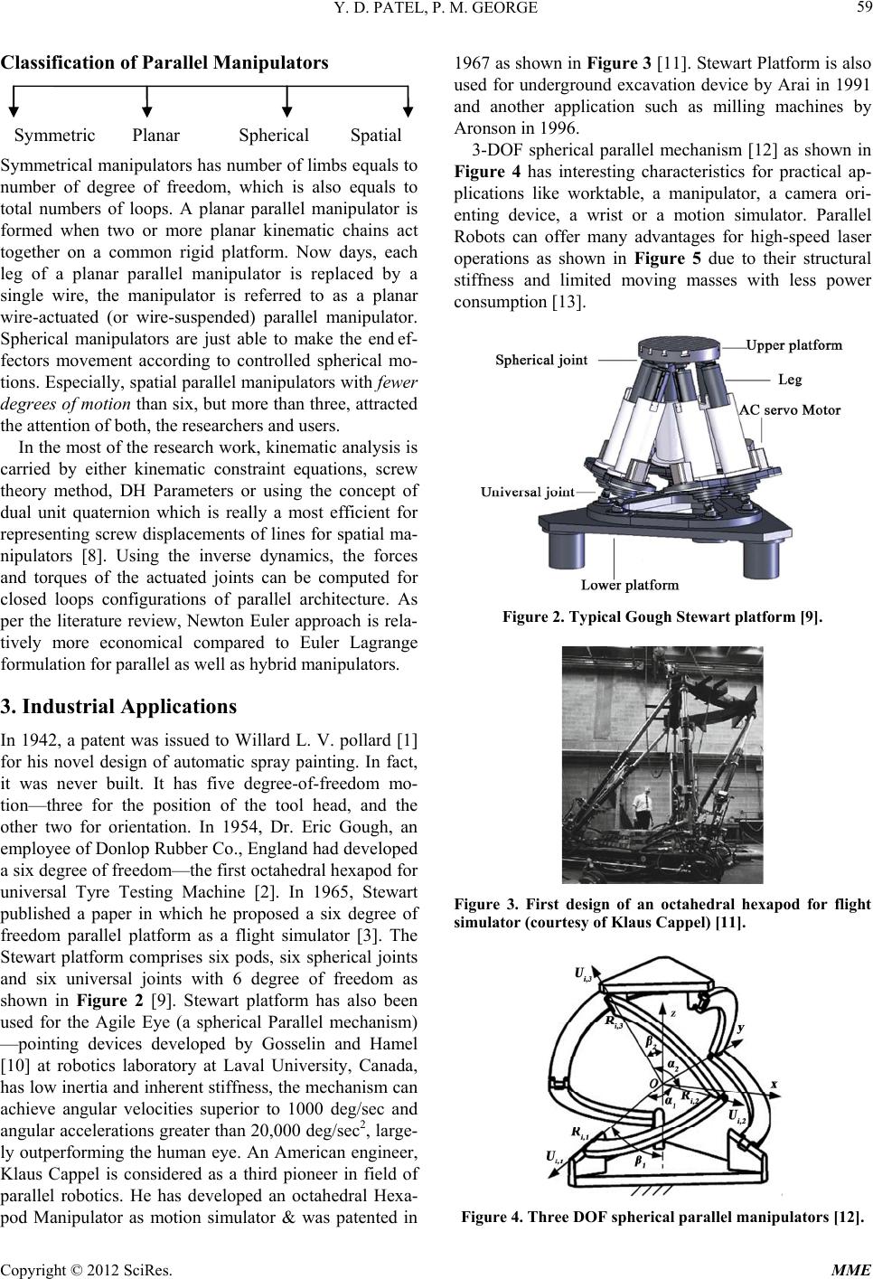 Y. D. PATEL, P. M. GEORGE 59 Classification of Parallel Manipulators Symmetric Planar Spherical Spatial Symmetrical manipulators has number of limbs equals to number of degree of freedom, which is also equals to total numbers of loops. A planar parallel manipulator is formed when two or more planar kinematic chains act together on a common rigid platform. Now days, each leg of a planar parallel manipulator is replaced by a single wire, the manipulator is referred to as a planar wire-actuated (or wire-suspended) parallel manipulator. Spherical manipulators are just able to make the end ef- fectors movement according to controlled spherical mo- tions. Especially, spatial parallel manipulators with fewer degrees of motion than six, but more than three, attracted the attention of both, the researchers and users. In the most of the research work, kinematic analysis is carried by either kinematic constraint equations, screw theory method, DH Parameters or using the concept of dual unit quaternion which is really a most efficient for representing screw displacements of lines for spatial ma- nipulators [8]. Using the inverse dynamics, the forces and torques of the actuated joints can be computed for closed loops configurations of parallel architecture. As per the literature review, Newton Euler approach is rela- tively more economical compared to Euler Lagrange formulation for parallel as well as hybrid manipulators. 3. Industrial Applications In 1942, a patent was issued to Willard L. V. pollard [1] for his novel design of automatic spray painting. In fact, it was never built. It has five degree-of-freedom mo- tion—three for the position of the tool head, and the other two for orientation. In 1954, Dr. Eric Gough, an employee of Donlop Rubber Co., England had developed a six degree of freedom—the first octahedral hexapod for universal Tyre Testing Machine [2]. In 1965, Stewart published a paper in which he proposed a six degree of freedom parallel platform as a flight simulator [3]. The Stewart platform comprises six pods, six spherical joints and six universal joints with 6 degree of freedom as shown in Figure 2 [9]. Stewart platform has also been used for the Agile Eye (a spherical Parallel mechanism) —pointing devices developed by Gosselin and Hamel [10] at robotics laboratory at Laval University, Canada, has low inertia and inherent stiffness, the mechanism can achieve angular velocities superior to 1000 deg/sec and angular accelerations greater than 20,000 deg/sec2, large- ly outperforming the human eye. An American engineer, Klaus Cappel is considered as a third pioneer in field of parallel robotics. He has developed an octahedral Hexa- pod Manipulator as motion simulator & was patented in 1967 as shown in Figure 3 [11]. Stewart Platform is also used for underground excavation device by Arai in 1991 and another application such as milling machines by Aronson in 1996. 3-DOF spherical parallel mechanism [12] as shown in Figure 4 has interesting characteristics for practical ap- plications like worktable, a manipulator, a camera ori- enting device, a wrist or a motion simulator. Parallel Robots can offer many advantages for high-speed laser operations as shown in Figure 5 due to their structural stiffness and limited moving masses with less power consumption [13]. Figure 2. Typical Gough Stewar t platfor m [9]. Figure 3. First design of an octahedral hexapod for flight simulator (courtesy of Klaus Cappel) [11]. Figure 4. Three DOF spherical parallel manipulators [12]. Copyright © 2012 SciRes. MME 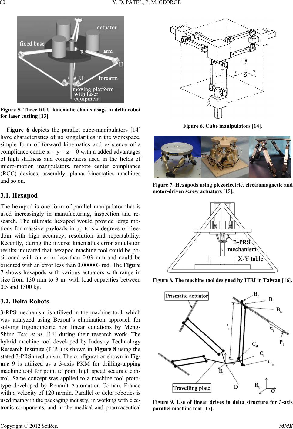 Y. D. PATEL, P. M. GEORGE 60 Figure 5. Three RUU kinematic chains usage in delta robot for laser cutting [13]. Figure 6 depicts the parallel cube-manipulators [14] have characteristics of no singularities in the workspace, simple form of forward kinematics and existence of a compliance centre x = y = z = 0 with a added advantages of high stiffness and compactness used in the fields of micro-motion manipulators, remote center compliance (RCC) devices, assembly, planar kinematics machines and so on. 3.1. Hexapod The hexapod is one form of parallel manipulator that is used increasingly in manufacturing, inspection and re- search. The ultimate hexapod would provide large mo- tions for massive payloads in up to six degrees of free- dom with high accuracy, resolution and repeatability. Recently, during the inverse kinematics error simulation results indicated that hexapod machine tool could be po- sitioned with an error less than 0.03 mm and could be oriented with an error less than 0.000003 rad. The Figure 7 shows hexapods with various actuators with range in size from 130 mm to 3 m, with load capacities between 0.5 and 1500 kg. 3.2. Delta Robots 3-RPS mechanism is utilized in the machine tool, which was analyzed using Bezout’s elimination approach for solving trigonometric non linear equations by Meng- Shiun Tsai et al. [16] during their research work. The hybrid machine tool developed by Industry Technology Research Institute (ITRI) is shown in Figure 8 using the stated 3-PRS mechanism. The configuration shown in Fig- ure 9 is utilized as a 3-axis PKM for drilling-tapping machine tool for point to point high speed accurate con- trol. Same concept was applied to a machine tool proto- type developed by Renault Automation Comau, France with a velocity of 120 m/min. Parallel or delta robotics is used mainly in the packaging industry, in working with elec- tronic components, and in the medical and pharmaceutical Figure 6. Cube manipulators [14]. Figure 7. Hexapods using piezoelectric, electromagnetic and motor-driven screw actuators [15]. Figure 8. The machin e tool designed by ITRI in Taiwan [16]. Figure 9. Use of linear drives in delta structure for 3-axis parallel machine tool [17]. Copyright © 2012 SciRes. MME 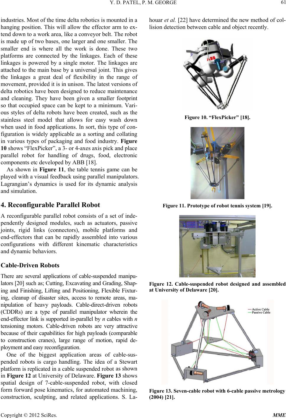 Y. D. PATEL, P. M. GEORGE 61 industries. Most of the time delta robotics is mounted in a hanging position. This will allow the effector arm to ex- tend down to a work area, like a conveyor belt. The robot is made up of two bases, one larger and one smaller. The smaller end is where all the work is done. These two platforms are connected by the linkages. Each of these linkages is powered by a single motor. The linkages are attached to the main base by a universal joint. This gives the linkages a great deal of flexibility in the range of movement, provided it is in unison. The latest versions of delta robotics have been designed to reduce maintenance and cleaning. They have been given a smaller footprint so that occupied space can be kept to a minimum. Vari- ous styles of delta robots have been created, such as the stainless steel model that allows for easy wash down when used in food applications. In sort, this type of con- figuration is widely applicable as a sorting and collating in various types of packaging and food industry. Figure 10 shows “FlexPicker”, a 3- or 4-axes axis pick and place parallel robot for handling of drugs, food, electronic components etc developed by ABB [18]. As shown in Figure 11, the table tennis game can be played with a visual feedback using parallel manipulators. Lagrangian’s dynamics is used for its dynamic analysis and simulation. 4. Reconfigurable Parallel Robot A reconfigurable parallel robot consists of a set of inde- pendently designed modules, such as actuators, passive joints, rigid links (connectors), mobile platforms and end-effectors that can be rapidly assembled into various configurations with different kinematic characteristics and dynamic behaviors. Cable-Driven Robots There are several applications of cable-suspended manipu- lators [20] such as; Cutting, Excavating and Grading, Shap- ing and Finishing, Lifting and Positioning, Flexible Fixtur- ing, cleanup of disaster sites, access to remote areas, ma- nipulation of heavy payloads. Cable-direct-driven robots (CDDRs) are a type of parallel manipulator wherein the end-effector link is supported in-parallel by n cables with n tensioning motors. Cable-driven robots are very attractive because of their capabilities for high payloads (comparable to construction cranes), large range of motion, rapid de- ployment and easy reconfiguration. One of the biggest application areas of cable-sus- pended robots is cargo handling. The idea of a Stewart platform is replicated in a cable suspended robot as shown in Figure 12 at University of Delaware. Figure 13 shows spatial design of 7-cable-suspended robot, with closed form forward pose kinematics, for automated machining, construction, sculpting, and related applications. S. La- houar et al. [22] have determined the new method of col- lision detection between cable and object recently. Figure 10. “FlexPicker” [18]. Figure 11. Prototype of robot tennis system [19]. Figure 12. Cable-suspended robot designed and assembled at University of Delaware [20]. Figure 13. Seven-cable robot with 6-cable passive metrology (2004) [21]. Copyright © 2012 SciRes. MME 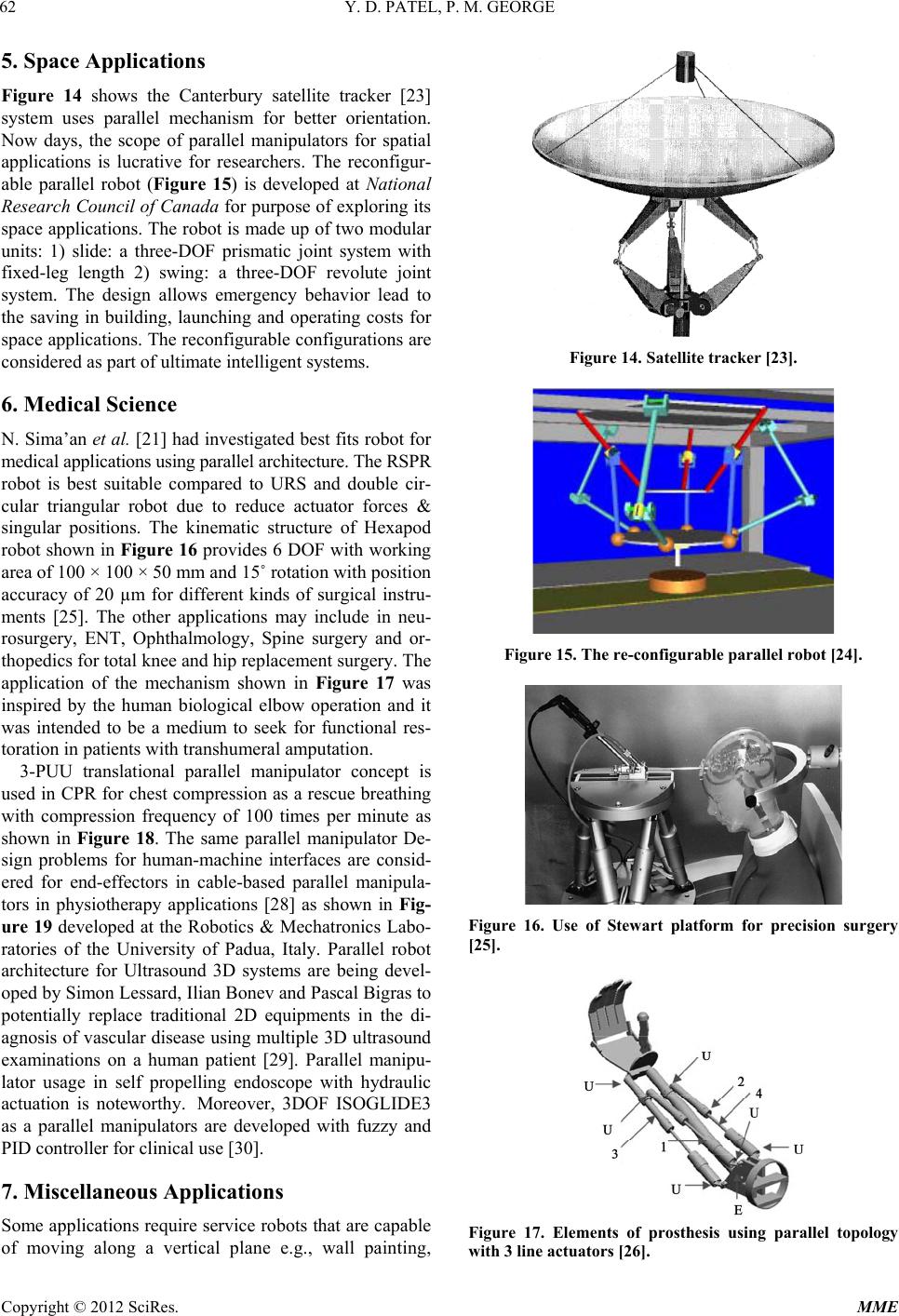 Y. D. PATEL, P. M. GEORGE 62 5. Space Applications Figure 14 shows the Canterbury satellite tracker [23] system uses parallel mechanism for better orientation. Now days, the scope of parallel manipulators for spatial applications is lucrative for researchers. The reconfigur- able parallel robot (Figure 15) is developed at National Research Council of Canada for purpose of exploring its space applications. The robot is made up of two modular units: 1) slide: a three-DOF prismatic joint system with fixed-leg length 2) swing: a three-DOF revolute joint system. The design allows emergency behavior lead to the saving in building, launching and operating costs for space applications. The reconfigurable configurations are considered as part of ultimate intelligent systems. 6. Medical Science N. Sima’an et al. [21] had investigated best fits robot for medical applications using parallel architecture. The RSPR robot is best suitable compared to URS and double cir- cular triangular robot due to reduce actuator forces & singular positions. The kinematic structure of Hexapod robot shown in Figure 16 provides 6 DOF with working area of 100 × 100 × 50 mm and 15˚ rotation with position accuracy of 20 µm for different kinds of surgical instru- ments [25]. The other applications may include in neu- rosurgery, ENT, Ophthalmology, Spine surgery and or- thopedics for total knee and hip replacement surgery. The application of the mechanism shown in Figure 17 was inspired by the human biological elbow operation and it was intended to be a medium to seek for functional res- toration in patients with transhumeral amputation. 3-PUU translational parallel manipulator concept is used in CPR for chest compression as a rescue breathing with compression frequency of 100 times per minute as shown in Figure 18. The same parallel manipulator De- sign problems for human-machine interfaces are consid- ered for end-effectors in cable-based parallel manipula- tors in physiotherapy applications [28] as shown in Fig- ure 19 developed at the Robotics & Mechatronics Labo- ratories of the University of Padua, Italy. Parallel robot architecture for Ultrasound 3D systems are being devel- oped by Simon Lessard, Ilian Bonev and Pascal Bigras to potentially replace traditional 2D equipments in the di- agnosis of vascular disease using multiple 3D ultrasound examinations on a human patient [29]. Parallel manipu- lator usage in self propelling endoscope with hydraulic actuation is noteworthy. Moreover, 3DOF ISOGLIDE3 as a parallel manipulators are developed with fuzzy and PID controller for clinical use [30]. 7. Miscellaneous Applications Some applications require service robots that are capable of moving along a vertical plane e.g., wall painting, Figure 14. Satellite tracker [23]. Figure 15. The re-configurable parallel robot [24]. Figure 16. Use of Stewart platform for precision surgery [25]. Figure 17. Elements of prosthesis using parallel topology with 3 line actuators [26]. Copyright © 2012 SciRes. MME 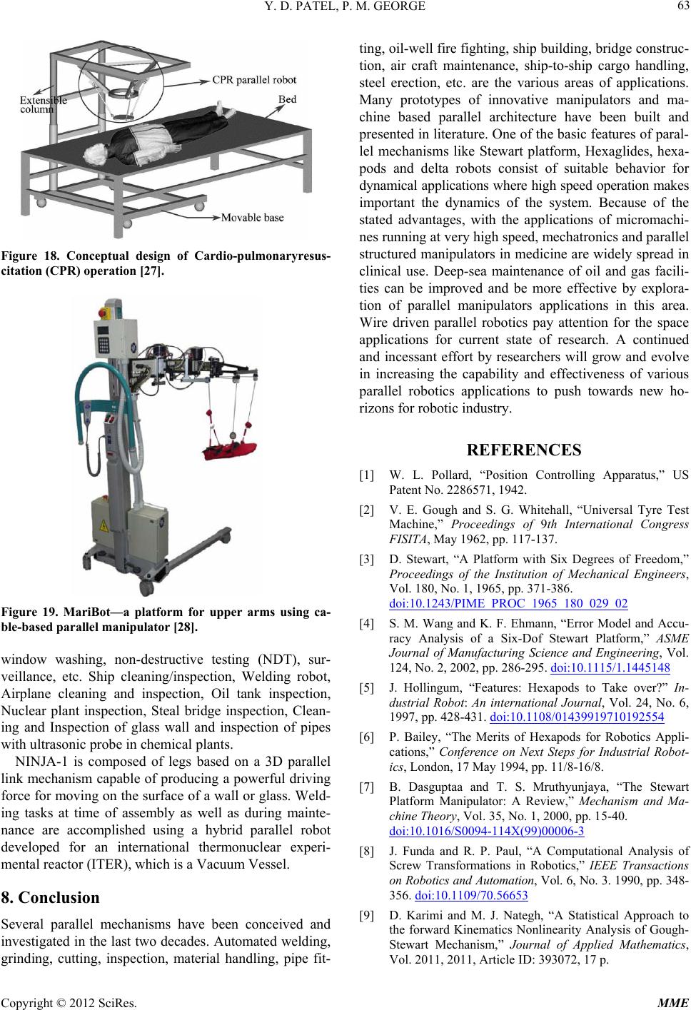 Y. D. PATEL, P. M. GEORGE 63 Figure 18. Conceptual design of Cardio-pulmonaryresus- citation (CPR) operation [27]. Figure 19. MariBot—a platform for upper arms using ca- ble-based parallel manipulator [28]. window washing, non-destructive testing (NDT), sur- veillance, etc. Ship cleaning/inspection, Welding robot, Airplane cleaning and inspection, Oil tank inspection, Nuclear plant inspection, Steal bridge inspection, Clean- ing and Inspection of glass wall and inspection of pipes with ultrasonic probe in chemical plants. NINJA-1 is composed of legs based on a 3D parallel link mechanism capable of producing a powerful driving force for moving on the surface of a wall or glass. Weld- ing tasks at time of assembly as well as during mainte- nance are accomplished using a hybrid parallel robot developed for an international thermonuclear experi- mental reactor (ITER), which is a Vacuum Vessel. 8. Conclusion Several parallel mechanisms have been conceived and investigated in the last two decades. Automated welding, grinding, cutting, inspection, material handling, pipe fit- ting, oil-well fire fighting, ship building, bridge construc- tion, air craft maintenance, ship-to-ship cargo handling, steel erection, etc. are the various areas of applications. Many prototypes of innovative manipulators and ma- chine based parallel architecture have been built and presented in literature. One of the basic features of paral- lel mechanisms like Stewart platform, Hexaglides, hexa- pods and delta robots consist of suitable behavior for dynamical applications where high speed operation makes important the dynamics of the system. Because of the stated advantages, with the applications of micromachi- nes running at very high speed, mechatronics and parallel structured manipulators in medicine are widely spread in clinical use. Deep-sea maintenance of oil and gas facili- ties can be improved and be more effective by explora- tion of parallel manipulators applications in this area. Wire driven parallel robotics pay attention for the space applications for current state of research. A continued and incessant effort by researchers will grow and evolve in increasing the capability and effectiveness of various parallel robotics applications to push towards new ho- rizons for robotic industry. REFERENCES [1] W. L. Pollard, “Position Controlling Apparatus,” US Patent No. 2286571, 1942. [2] V. E. Gough and S. G. Whitehall, “Universal Tyre Test Machine,” Proceedings of 9th International Congress FISITA, May 1962, pp. 117-137. [3] D. Stewart, “A Platform with Six Degrees of Freedom,” Proceedings of the Institution of Mechanical Engineers, Vol. 180, No. 1, 1965, pp. 371-386. doi:10.1243/PIME_PROC_1965_180_029_02 [4] S. M. Wang and K. F. Ehmann, “Error Model and Accu- racy Analysis of a Six-Dof Stewart Platform,” ASME Journal of Manufacturing Science and Engineering, Vol. 124, No. 2, 2002, pp. 286-295. doi:10.1115/1.1445148 [5] J. Hollingum, “Features: Hexapods to Take over?” In- dustrial Robot: An international Journal, Vol. 24, No. 6, 1997, pp. 428-431. doi:10.1108/01439919710192554 [6] P. Bailey, “The Merits of Hexapods for Robotics Appli- cations,” Conference on Next Steps for Industrial Robot- ics, London, 17 May 1994, pp. 11/8-16/8. [7] B. Dasguptaa and T. S. Mruthyunjaya, “The Stewart Platform Manipulator: A Review,” Mechanism and Ma- chine Theory, Vol. 35, No. 1, 2000, pp. 15-40. doi:10.1016/S0094-114X(99)00006-3 [8] J. Funda and R. P. Paul, “A Computational Analysis of Screw Transformations in Robotics,” IEEE Transactions on Robotics and Automation, Vol. 6, No. 3. 1990, pp. 348- 356. doi:10.1109/70.56653 [9] D. Karimi and M. J. Nategh, “A Statistical Approach to the forward Kinematics Nonlinearity Analysis of Gough- Stewart Mechanism,” Journal of Applied Mathematics, Vol. 2011, 2011, Article ID: 393072, 17 p. Copyright © 2012 SciRes. MME 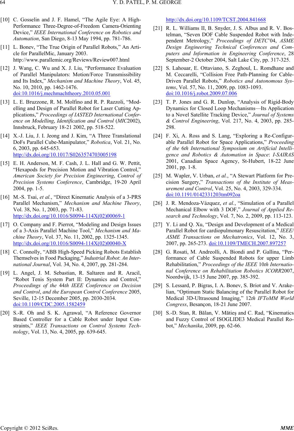 Y. D. PATEL, P. M. GEORGE Copyright © 2012 SciRes. MME 64 [10] C. Gosselin and J. F. Hamel, “The Agile Eye: A High- Performance Three-Degree-of-Freedom Camera-Orienting Device,” IEEE International Conference on Robotics and Automation, San Diego, 8-13 May 1994, pp. 781-786. [11] L. Bonev, “The True Origin of Parallel Robots,” An Arti- cle for ParallelMic, January 2003. http://www.parallemic.org/Reviews/Review007.html [12] J. Wang, C. Wu and X. J. Liu, “Performance Evaluation of Parallel Manipulators: Motion/Force Transmissibility and Its Index,” Mechanism and Machine Theory, Vol. 45, No. 10, 2010, pp. 1462-1476. doi:10.1016/j.mechmachtheory.2010.05.001 [13] L. E. Bruzzone, R. M. Molfino and R. P. Razzoli, “Mod- elling and Design of Parallel Robot for Laser Cutting Ap- plications,” Proceedings of IASTED International Confer- ence on Modelling, Identification and Control (MIC2002), Innsbruck, February 18-21 2002, pp. 518-522. [14] X.-J. Liu, J. I. Jeong and J. Kim, “A Three Translational DoFs Parallel Cube-Manipulator,” Robotica, Vol. 21, No. 6, 2003, pp. 645-653. http://dx.doi.org/10.1017/S0263574703005198 [15] E. H. Anderson, M. F. Cash, J. L. Hall and G. W. Pettit, “Hexapods for Precision Motion and Vibration Control,” American Society for Precision Engineering, Control of Precision Systems Conference, Cambridge, 19-20 April 2004, pp. 1-5. [16] M.-S. Tsai, et al., “Direct Kinematic Analysis of a 3-PRS Parallel Mechanism,” Mechanism and Machine Theory, Vol. 38, No. 1, 2003, pp. 71-83. http://dx.doi.org/10.1016/S0094-114X(02)00069-1 [17] O. Company and F. Pierrot, “Modeling and Design Issues of a 3-Axis Parallel Machine Tool,” Mechanism and Ma- chine Theory, Vol. 37, No. 11, 2002, pp. 1325-1345. http://dx.doi.org/10.1016/S0094-114X(02)00040-X [18] C. Connolly, “ABB High-Speed Picking Robots Establish Themselves in Food Packaging,” Industrial Robot : An Inter- national Journal, Vol. 34, No. 4, 2007, pp. 281-284. [19] L. Angel, J. M. Sebastian, R. Saltaren and R. Aracil, “Robot Tenis System Part II: Dynamics and Control,” Proceedings of the 44th IEEE Conference on Decision and Control, and the European Control Conference 2005, Seville, 12-15 December 2005, pp. 2030-2034. doi:10.1109/CDC.2005.1582459 [20] S.-R. Oh and S. K. Agrawal, “A Reference Governor Based Controller for a Cable Robot under Input Con- straints,” IEEE Transactions on Control Systems Tech- nology, Vol. 13, No. 4, 2005, pp. 639-645. http://dx.doi.org/10.1109/TCST.2004.841668 [21] R. L. Williams II, B. Snyder, J. S. Albus and R. V. Bos- telman, “Seven DOF Cable Suspended Robot with Inde- pendent Metrology,” Proceedings of DETC’04, ASME Design Engineering Technical Conferences and Com- puters and Information in Engineering Conference, 28 September-2 October 2004, Salt Lake City, pp. 317-325. [22] S. Lahouar, E. Ottaviano, S. Zeghoul, L. Romdhane and M. Ceccarelli, “Collision Free Path-Planning for Cable- Driven Parallel Robots,” Robotics and Autonomous Sys- tems, Vol. 57, No. 11, 2009, pp. 1083-1093. doi:10.1016/j.robot.2009.07.006 [23] T. P. Jones and G. R. Dunlop, “Analysis of Rigid-Body Dynamics for Closed Loop Mechanisms—Its Application to a Novel Satellite Tracking Device,” Journal of Systems & Control Engineering, Vol. 217, No. 4, 2003, pp. 285- 298. [24] F. Xi, A. Ross and S. Lang, “Exploring a Re-Configur- able Parallel Robot for Space Applications,” Proceeding of the 6th International Symposium on Artificial Intelli- gence and Robotics & Automation in Space: I-SAIRAS 2001, Canadian Space Agency, St-Hubert, 18-22 June 2001, pp. 1-8. [25] M. Wapler, V. Urban, et al., “A Stewart Platform for Pre- cision Surgery,” Transactions of the Institute of Meas- urement and Control, Vol. 25, No. 4, 2003, 329-334. doi:10.1191/0142331203tm092oa [26] J. R. Mendoza-Vázquez, et al., “Simulation of a Parallel Mechanical Elbow with 3 DOF,” Journal of Applied Re- search and Technology, Vol. 7, No. 2, 2009, pp. 113-123. [27] Y. Li and Q. Xu, “Design and Development of a Medical Parallel Robot for cardiopulmonary Resuscitation,” IEEE/ ASME Transactions on Mechatronics, Vol. 12, No. 3, 2007, pp. 265-273. doi:10.1109/TMECH.2007.897257 [28] G. Rosati, M. Andreolli, A. Biondi and P. Gallina, “Per- formance of Cable Suspended Robots for upper Limb Rehabilitation,” Proceedings of the IEEE 10th Internatio- nal Conference on Rehabilitation Robotics ICORR2007, Noordwijk, 13-15 June 2007, pp. 385-392. [29] S. Lessard, P. Bigras, I. A. Bonev, S. Briot and V. Arake- lian, “Optimum Static Balancing of the Parallel Robot for Medical 3D-Ultrasound Imaging,” 12th IFToMM World Congress, Besançon, 18-21 June 2007. [30] S.-D. Stan, R. Bălan, V. Mătieş and C. Rad, “Kinematics and Fuzzy Control of ISOGLIDE3 Medical Parallel Ro- bot,” Mechanika, 2009, pp. 62-66.
|