 Journal of Modern Physics, 2012, 3, 762-773 http://dx.doi.org/10.4236/jmp.2012.38100 Published Online August 2012 (http://www.SciRP.org/journal/jmp) On the Absence of Carrier Drift in Two-Terminal Devices and the Origin of Their Lowest Resistance per Carrier RK = /q2 Jose Ignacio Izpura Group of Microsystems and Electronic Materials, GMME-CEMDATIC, Universidad Politécnica de Madrid (UPM), Madrid, Spain Email: joseignacio.izpura@upm.es Received May 21, 2012; revised June 19, 2012; accepted July 9, 2012 ABSTRACT After a criticism on today’s model for electrical noise in resistors, we pass to use a Quantum-compliant model based on the discreteness of electrical charge in a complex Admittance. From this new model we show that carrier drift viewed as charged particle motion in response to an electric field is unlike to occur in bulk regions of Solid-State devices where carriers react as dipoles against this field. The absence of the shot noise that charges drifting in resistors should produce and the evolution of the Phase Noise with the active power existing in the resonators of L-C oscillators, are two effects added in proof for this conduction model without carrier drift where the resistance of any two-terminal device becomes discrete and has a minimum value per carrier that is the Quantum resistance 2 K Rq . Keywords: Fluctuation-Dissipation; Energy Conversion into Heat; Two-Terminal Device; Discrete Resistance; Capacitance; Shot Noise; Quantum Hall Resistance 1. Introduction Few years ago, the work entitled: “On the first measure- ment of shot noise in macroscopic resistors by J. B. Johnson” was rejected on the basis of the empirical ab- sence of shot noise associated to a DC current in macro- scopic resistors. Taking this absence as a type of dogma, the rejection report stated: “Shot noise in resistors has never been observed up to now. There is no shot noise (proportional to the DC current) on top of the thermal noise. If some increase in thermal noise was observed by passing a current through the sample compared to the thermal noise without current through the resistor then it was due to a temperature increase of the sample. The classical way to explain the non existence of shot noise in resistors is to model the resistor by a large number of N diodes in series each with noise source 2qI parallel to a dynamic resistor rd. This results in a negligible current noise for N → ∞ as shown in: 2 2 22 d d NqIr qI N Nr I S (1) Since scientific dogmas use to be replaced by better ideas (not necessarily new ones) excelling them in some way, let us summarize the main contributions of this pa- per by rewriting these statements as: “Shot noise in re- sistors is observed routinely but disguised as Johnson noise. It comes from those electrons that pass randomly between terminals in Thermal Equilibrium (TE). There is no shot noise (proportional to the DC current) on top of the Thermal Noise (TN) because DC current is Switched Current that uses carrier polarization to emulate Resis- tance each time an electron passes between terminals. Thus, conduction current does not need electron pas- sages other than those that already exist in TE. If some increase in TN was observed by setting a DC current in the resistor compared to its TN without this current in the device, then it was due to a temperature increase of the device. The way these results are obtained is by using a Physical model for the resistor that shows why carrier drift is not a cogent mechanism to explain the conduction currents measured in Two-Terminal Devices (2TD) nei- ther the Joule Effect associated to them”. Since this paper is related with Instrumentation and Measurement let us define DC current and conduction current from the key role of the 2TD where they can be measured. Note that electrical current always is measured in a 2TD, not “in a material” as most people assume na- ively. Conduction current iP(t) is current in-Phase with a sinusoidal voltage v(t) between terminals of the 2TD. A C opyright © 2012 SciRes. JMP  J. I. IZPURA 763 different current also measured in a 2TD is its reactive current iQ(t) found in-Quadrature with v(t). It is worth noting that when electrons pass between terminals of a 2TD, they generate shot noise as it was observed long time ago [1,2] and this passage requires reactive currents iQ(t) in the 2TD (e.g. displacement currents), not conduc- tion ones iP(t). With regard “DC current”, it is conduction current ap- pearing when frequency f 0. In this case we have: v(t) 0 and 0,vt t thus v(t) = V0, constant or static during the measurement. The null derivative 0vt t suggests that no net displacement current is required to have DC current, or that there is no need for a net flux of charges crossing the 2TD. The sinusoidal forms of v(t), iP(t) and iQ(t) refer to the Fourier components of arbitrary voltages and currents in a 2TD. Thanks to less dogmatic referees, the reason why J. B. Johnson [3] already meas- ured shot noise in 1928, can be read in [4] that not only explains why “Shot noise in resistors appears disguised as Johnson noise in TE”, but also gives a Quantum com- pliant model for electrical noise in 2TDs that agrees with the Quantum treatment of noise published by Callen and Welton in 1951 [5]. Readers wishing to know more about the use in 2TDs of the Fluctuation-Dissipation Theorem derived from [5], could find [6] of interest. This paper is organized as follows. Section 2 criticises today’s model of electrical noise in resistors based on a lonely resistance R (conductance 1GR) driven by its Nyquist noise density 22 4AHzikTR n. This reflects the partial understanding of [7] shown in [4,6]. From the new model of [4], Section 3 shows that Joule effect is a Conversion of electrical energy into heat that differs from the Dissipation of electrical energy in the context of [5] because electrical energy converted into heat by Joule effect comes from a static field between terminals, but the energy Dissipated accordingly to [4-6] comes from thermal energy of the carriers previously converted into electrical one by a transducer that exists in the 2TD. Fi- nally, some conclusions are drawn at the end. To end this Introduction let us consider the system used to interact with a material (vacuum included [8]) in electrical measurements. We mean the 2TD that appears in Figure 1 for a one-dimensional (1-D) treatment of the electrical conduction in 2TDs like resistors. It is worth noting the capacitor formed by the two terminals (plates D-D) of high conductivity (σ ∞) used to apply electric fields to the material or to sense electric fields between terminals of this 2TD like its Fluctuations of electric field we called Thermal Actions (TA) in [4]. Hence, the ter- minals of a 2TD are connected by any electric field ap- pearing between them, in such a way that a Fluctuation of charge appearing on one terminal bears with it a si- multaneous Fluctuation (with opposed sign) of charge in the other. Since v(t) is the difference of two electrical potentials that appears simultaneously at terminals D-D in Figure 1, the capacitance C between terminals is the key element that links Cause (Fluctuations of charge in C) with its measurable Effect that is v(t). This key role does not depend on the resistance R between terminals and it allowed us to tell that Johnson noise of Solid-State resis- tors measured in V2/Hz is the Effect of a Cause (charge noise power in C2/s, Nyquist noise density in A2/Hz) that is the shot noise density of electrons passing randomly between the plates of C in the resistor [4]. 2. Criticism on Today’s View about Thermal Noise in Resistors Figure 1 also shows the starting point of the microscopic model widely accepted for the electrical conduction in Solid-State devices. This model considers electrons as particles moving randomly through the material between terminals of a resistor with thermal velocities vth ≈ 108 cm/s at room T (T = 300 K). Thus electrons are consid- ered as particles colliding with the material (thus within its volume) with a mean collision time τcoll of ps typi- cally). This gives a mean collision path λcoll ≈ 1 μm, much lower than the length L of macroscopic resistors. This model where charged particles of mass m* or carri- ers relax kinetic energy by collisions with relaxation time τcoll leads to a Lorentzian spectrum for the spectral den- sity of current fluctuations (in 2 AHz ) that is: 2 41 1 I c kT Sf R f (2) where fc = 1/(2πτcoll) and R is the Resistance that Ohm’s law gives for this parallelepiped of material, which is inversely proportional to the conductivity σ of the ho- mogeneous material between terminals D-D of Figure 1. It is worth noting that Equation (2) is not Nyquist for- mula with Plank’s constant [7], but the so-called Lorentz spectrum, flat below the characteristic frequency fc (fc ≈ 1012 Hz) and proportional to 2 1 for c f. Figure 1. Geometrical view (1-D) of a resistor made from a parallelepiped of material ended by two highly conducting “plates” or contacts. Copyright © 2012 SciRes. JMP  J. I. IZPURA 764 Because for c f Equation (2) gives the Nyquist density 2 4AHzkT R, τcoll tends to be considered as the more fundamental parameter to take into account the Brownian motion process underlying TN in resistors. This way, Equation (2) is considered as a microscopic explanation of Nyquist result and thus, the circuits used today to represent a noisy resistor remain those that were derived from [7] long time ago. They are in Figure 2, where the lonely resistance R seeks to represent a noise- less resistor whereas a noisy one is represented by this R together with a noise generator in parallel or in series (Norton and Thèvenin equivalents). However, we have shown in [6] that the Brownian motion process that really matters for electrical noise is the charge noise in C that Equation (2) does not consider at all. Because electrical noise requires the presence of electrical energy in the 2TD, the thermal origin of the electrical noise explained by Nyquist [7] suggests the presence of a Transducer#1 in the 2TD converting ki- netic energy of the carriers into electrical energy that, Fluctuating and being Dissipated in the 2TD accordingly to [5], would produce its electrical noise. Transducer#1 is no other than C [4], which also is the store of electrical energy we had to propose in [9] for Solid-State resistors and for reactive 2TDs associated to space charge regions that modulate their resistance so as to produce their 1/f “excess noise”. Since the collision model does not con- sider these facts, Equation (2) is unaware about the quan- tum mechanical factor given by Nyquist that is: 111 2 6 THz_ hf kT Q hf hf hf e kT kT fa h _300 K tT (3) where k is Boltzmann constant, T is temperature and h is Plank constant. The noise densities 22 4AHzikTR n (Nyquist noise) and 22 4 VHz n ekTR (Johnson noise) used in Figure 2 as in and en are constant up to frequen- cies fQ where Equation (3) departs from 2kT. Since the typical τcoll ≈ 1 ps found in the literature means that SI(f) drops around fc ≈ 0.16 THz, the high ratio 1ff Qc suggests that electrons “collide” or interact in a very dif- ferent way. Figure 2. Electrical circuits derived from a simplified view of Figure 1 that are widely used in noise calculations. From the analogy of this collision model with the ki- netic theory of gases and from the drift model that it re- quires for electrical conduction we have to admit that the material existing between plates D-D in Figure 1 con- tains a gas of charged particles, each carrying a charge –q ≈ –1.6 10–19 C. This gas is embedded in the material in such a way that these carriers can interact with the lattice but not among themselves. By this we mean that these electrons moving randomly generate electrical noise as the title of [7] suggests due to their electrical charge, but for the same reason, they would have to repel mutually. This makes hard to believe that these charged carriers remain within the material without colliding electrically among themselves to escape quickly towards its surfaces. The dielectric relaxation time d of the material between terminals of Figure 1 that links its dielectric permittivity ε with its conductivity σ, reflects the speed of this escape process and also gives a good reason to contend that if an electron exits in the form of a carrier within the bulk region of the 2TD of Figure 1, it will not be a unipolar charge, but a distributed dipole that, from time to time, will appear as a long-range dipole on the terminals of the 2TD, thus on its “surfaces” for the 1-D treatment we are employing. Another meaning of τd from the device viewpoint is that a resistor with the shape of Figure 1 will shunt by a capacitance dd CR the resistance R it offers be- tween terminals due to its material [9]. This shows that Figure 1 is not complete since it lacks an electrical di- pole appearing each time an electron is suddenly dis- placed within its volume. Added to this, Figure 1 also assumes that electrons can pass “partially” between ter- minals as it is shown by the “current induced by an elec- tron jump over λcoll < L”. We refer to the integral appear- ing in Figure 1 where the Quantum of charge appears multiplied by a ratio coll L (usually 1L coll ) that can take any continuous value. This means that we could obtain currents carrying fractions of q in the external circuit. Replacing the Ammeter Am of Figure 1 by a ca- pacitance CMeas we would have the first capacitor (to our knowledge) where the charge appearing on its plates would be any fraction of q. Moreover, we do not need to connect CMeas because C already is replacing the Amme- ter if we leave the 2TD of Figure 1 under open circuit conditions. To say it bluntly: accepting the collision model of Figure 1 we are renouncing to the quantization of elec- trical charge. Although the circuits of Figure 2 allow us to solve accurately noise problems for resistors in TE, let us show below that they are the origin of the above con- flict because the lonely resistance R of Figure 2 is not a complete representation of a noiseless resistor. The Admittance Y(jf) (measured in A/V or Ω–1) of the circuit of Figure 2 is: Copyright © 2012 SciRes. JMP  J. I. IZPURA 765 00 jG j 1 B YjfG jR (4) where f is the measuring frequency and j is the imaginary unit that multiplies a null Susceptance B(jf) = 0 because there are not reactive elements in this circuit. Neglecting edge effects due to the 1-D treatment at hand, the Y(jf) of a device with the geometry of Figure 1 will be [8,9]: 2πd GjfG 12πd Yjfj f RR (5) Comparing Equations (4) and (5) we observe that the lonely R of Figure 2 can not represent the dielectric properties of the 2TD of Figure 1 whose plates D-D clad a volume of non null permittivity ε ≠ 0, thus requiring a capacitance Cd in parallel with R. Although this Cd = τd/R was found from Thermodynamics [9], the Complex Im- pedance that appears repeatedly in [5] means that Quan- tum Physics also demands a complex Admittance to de- scribe noisy devices. Hence, none of the circuits of Fig- ure 2 are Quantum representations of the noisy resistor of Figure 1 because they do not allow for the existence of Fluctuations of electrical energy in the 2TD of Figure 1. This is why we need the circuit of Figure 3 to have a Physical model for resistors and capacitors [4-6,8,9]. Another objection to the collision model is the non null time it assumes for electrons travelling between ter- minals of the 2TD after a series of collisions. We mean that an electron emitted from one of the terminals arrives in the other terminal at a latter time ∆ttransit, after many collisions with the matter between terminals. Unaware of C, this is the only option for electrons to pass between terminals and to account for the conduction current in 2TDs. However, C is a much easier and faster path for this purpose. By a Fluctuation of electric field in C an electron will jump instantaneously the whole length L of Figure 1 (recall the simultaneous Fluctuations of charge in the plates of C) and although a mean collision path λcoll ≈ 1 μm hardly would suggest such a jump for L ≈ 1 cm in Figure 1, the existence of C makes believable (and likely) these jumps that we called TAs. The Cause-Effect link between noise currents iQ(t) and iP(t) in the circuit of Figure 3 [4,6] strongly suggests that electrons use C to pass between the terminals of a 2TD. When a TA occurs the electron that has passed between terminals of the 2TD sets an energy 22Eq C J in t = 0. This is the way Transducer#1 converts kinetic energy Figure 3. Electrical circuit giving a cogent representation of noisy devices like resistors or capacitors with the shape of Figure 1 [4]. of carriers into a Fluctuation of electrical energy (Cause) subsequently Dissipated (Effect) [4]. Once this energy is in C, it starts to relax by a slower conduction current linked with R that Dissipates this Fluctuation ∆E in the 2TD. This is the Device Reaction (DR) [4], where the reuse of the path through C in opposed sense to remove quickly ∆E is avoided by this relaxation itself. The en- ergy ∆E(t = 0+) existing in C slightly after the TA born in t = 0 will be lower than 22qC . This means that the electron just displaced has not enough energy to jump back through C and the 2TD has to use the slower path that involves R to continue dissipating this ∆E(t = 0+). The non null time ∆t required to build a TA (see below) means that a 2TD having suffered one, will spend some time ∆t before being ready for a new TA no matter its sign. This guarantees ∆E(t = 0+) < 22qC and avoids the “backward jump” of the displaced electron. Learning from [7], H. Nyquist had to build a device with both dissipative and reactive elements to explain the thermal origin of the noise measured by Johnson [3]. We refer to the Transmission Line (TL) he ended by two “conductors of pure resistance R” (sic), likely because he knew well the meaning of Equation (5). The Susceptance of this TL made possible Fluctuations of electrical en- ergy at each f or the Degree of Freedom (DF) he needed to apply Equipartition. It is worth noting that the null B(jf0) = 0 of the tuned TL of [7] at each f or that of an L-C tank at its resonance frequency 12 2πfLC 0 both imply presence of susceptance in the 2TD, not its absence. This presence of two susceptances of equal magnitude but opposed sign creates the null disposition of the 2TD to vary its energy content in response to si- nusoidal currents at f0. However, this presence allows for the Fluctuation of energy content in the circuit under -like currents like TAs. The absence of susceptance would make the 2TD to- tally unable to store electrical energy and hence, unable to show Fluctuations (TAs) of this type of energy. Thus, the susceptance of a resistor should not be despised to study its noise as it is done in the circuits of Figure 2. A low C value (e.g. C < 10–13 F) should not be despised in Figure 1 because it means that the bandwidth of the 2TD is wide enough so as to accumulate the thermal fluctua- tion 2kT J from the flat density SV = 4kTR V2/Hz [4,6]. Thus, R is a spectrum shaper to accomplish Equipartion in C, a novelty that added to the discrete nature of the electrical charge gives a better model for thermal noise than that coming from Figure 2 [4]. To assume C = 0 in Figure 1 leads to assume naively absence of susceptance in this device and this wrong idea shows the partial in- terpretation of [7] that we reveal in [4]. This idea about C = 0 likely comes from a misunder- standing of Susceptance as the ability of circuits to store electrical energy. Looking for its true meaning one finds Copyright © 2012 SciRes. JMP 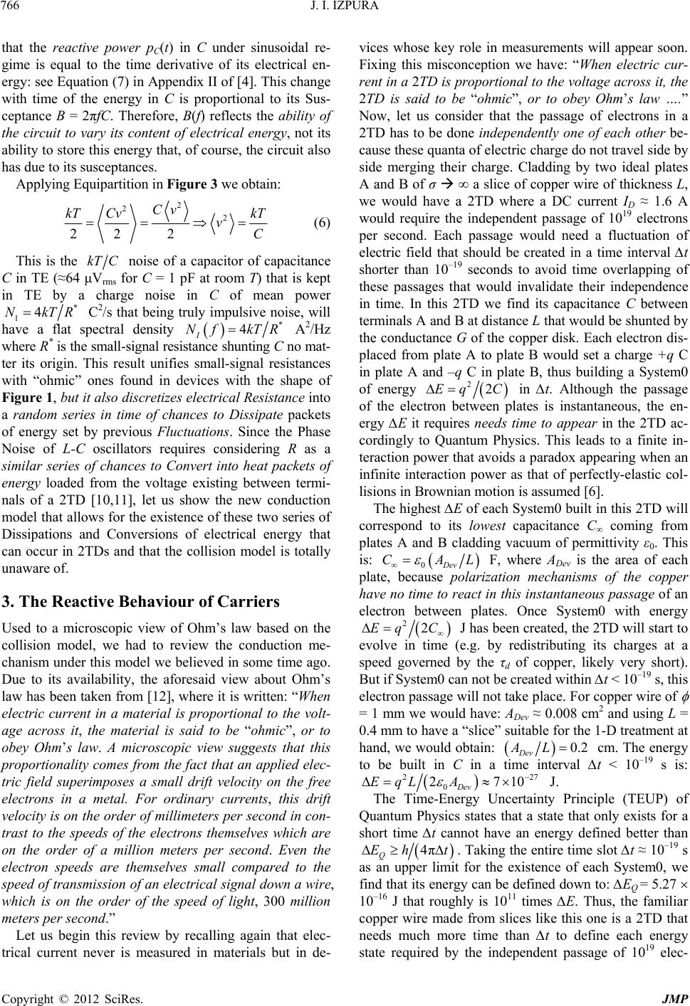 J. I. IZPURA 766 that the reactive power pC(t) in C under sinusoidal re- gime is equal to the time derivative of its electrical en- ergy: see Equation (7) in Appendix II of [4]. This change with time of the energy in C is proportional to its Sus- ceptance B = 2πfC. Therefore, B(f) reflects the ability of the circuit to vary its content of electrical energy, not its ability to store this energy that, of course, the circuit also has due to its susceptances. Applying Equipartition in Figure 3 we obtain: 2 2 22 2 Cv kT Cv 2kT vC (6) This is the kTC noise of a capacitor of capacitance C in TE (≈64 μVrms for C = 1 pF at room T) that is kept in TE by a charge noise in C of mean power * TR 1 C 2/s that being truly impulsive noise, will have a flat spectral density 4Nk * 4kTR I A2/Hz where R* is the small-signal resistance shunting C no mat- ter its origin. This result unifies small-signal resistances with “ohmic” ones found in devices with the shape of Figure 1, but it also discretizes electrical Resistance into a random series in time of chances to Dissipate packets of energy set by previous Fluctuations. Since the Phase Noise of L-C oscillators requires considering R as a similar series of chances to Convert into heat packets of energy loaded from the voltage existing between termi- nals of a 2TD [10,11], let us show the new conduction model that allows for the existence of these two series of Dissipations and Conversions of electrical energy that can occur in 2TDs and that the collision model is totally unaware of. Nf 3. The Reactive Behaviour of Carriers Used to a microscopic view of Ohm’s law based on the collision model, we had to review the conduction me- chanism under this model we believed in some time ago. Due to its availability, the aforesaid view about Ohm’s law has been taken from [12], where it is written: “When electric current in a material is proportional to the volt- age across it, the material is said to be “ohmic”, or to obey Ohm’s law. A microscopic view suggests that this proportionality comes from the fact that an applied elec- tric field superimposes a small drift velocity on the free electrons in a metal. For ordinary currents, this drift velocity is on the order of millimeters per second in con- trast to the speeds of the electrons themselves which are on the order of a million meters per second. Even the electron speeds are themselves small compared to the speed of transmission of an electrical signal down a wire, which is on the order of the speed of light, 300 million meters per second.” Let us begin this review by recalling again that elec- trical current never is measured in materials but in de- vices whose key role in measurements will appear soon. Fixing this misconception we have: “When electric cur- rent in a 2TD is proportional to the voltage across it, the 2TD is said to be “ohmic”, or to obey Ohm’s law ….” Now, let us consider that the passage of electrons in a 2TD has to be done independently one of each other be- cause these quanta of electric charge do not travel side by side merging their charge. Cladding by two ideal plates A and B of σ ∞ a slice of copper wire of thickness L, we would have a 2TD where a DC current ID ≈ 1.6 A would require the independent passage of 1019 electrons per second. Each passage would need a fluctuation of electric field that should be created in a time interval ∆t shorter than 10–19 seconds to avoid time overlapping of these passages that would invalidate their independence in time. In this 2TD we find its capacitance C between terminals A and B at distance L that would be shunted by the conductance G of the copper disk. Each electron dis- placed from plate A to plate B would set a charge +q C in plate A and –q C in plate B, thus building a System0 of energy 22Eq C in ∆t. Although the passage of the electron between plates is instantaneous, the en- ergy ∆E it requires needs time to appear in the 2TD ac- cordingly to Quantum Physics. This leads to a finite in- teraction power that avoids a paradox appearing when an infinite interaction power as that of perfectly-elastic col- lisions in Brownian motion is assumed [6]. The highest ∆E of each System0 built in this 2TD will correspond to its lowest capacitance C∞ coming from plates A and B cladding vacuum of permittivity ε0. This is: CAL 0Dev F, where ADev is the area of each plate, because polarization mechanisms of the copper have no time to react in this instantaneous passage of an electron between plates. Once System0 with energy 22EqC J has been created, the 2TD will start to evolve in time (e.g. by redistributing its charges at a speed governed by the τd of copper, likely very short). But if System0 can not be created within ∆t < 10–19 s, this electron passage will not take place. For copper wire of = 1 mm we would have: ADev ≈ 0.008 cm2 and using L = 0.4 mm to have a “slice” suitable for the 1-D treatment at hand, we would obtain: 0.2AL Dev cm. The energy to be built in C in a time interval ∆t < 10–19 s is: 227 2710EqL A 0Dev The Time-Energy Uncertainty Principle (TEUP) of Quantum Physics states that a state that only exists for a short time ∆t cannot have an energy defined better than J. 4πEh t Q. Taking the entire time slot ∆t ≈ 10–19 s as an upper limit for the existence of each System0, we find that its energy can be defined down to: ∆EQ = 5.27 10–16 J that roughly is 1011 times ∆E. Thus, the familiar copper wire made from slices like this one is a 2TD that needs much more time than ∆t to define each energy state required by the independent passage of 1019 elec- Copyright © 2012 SciRes. JMP 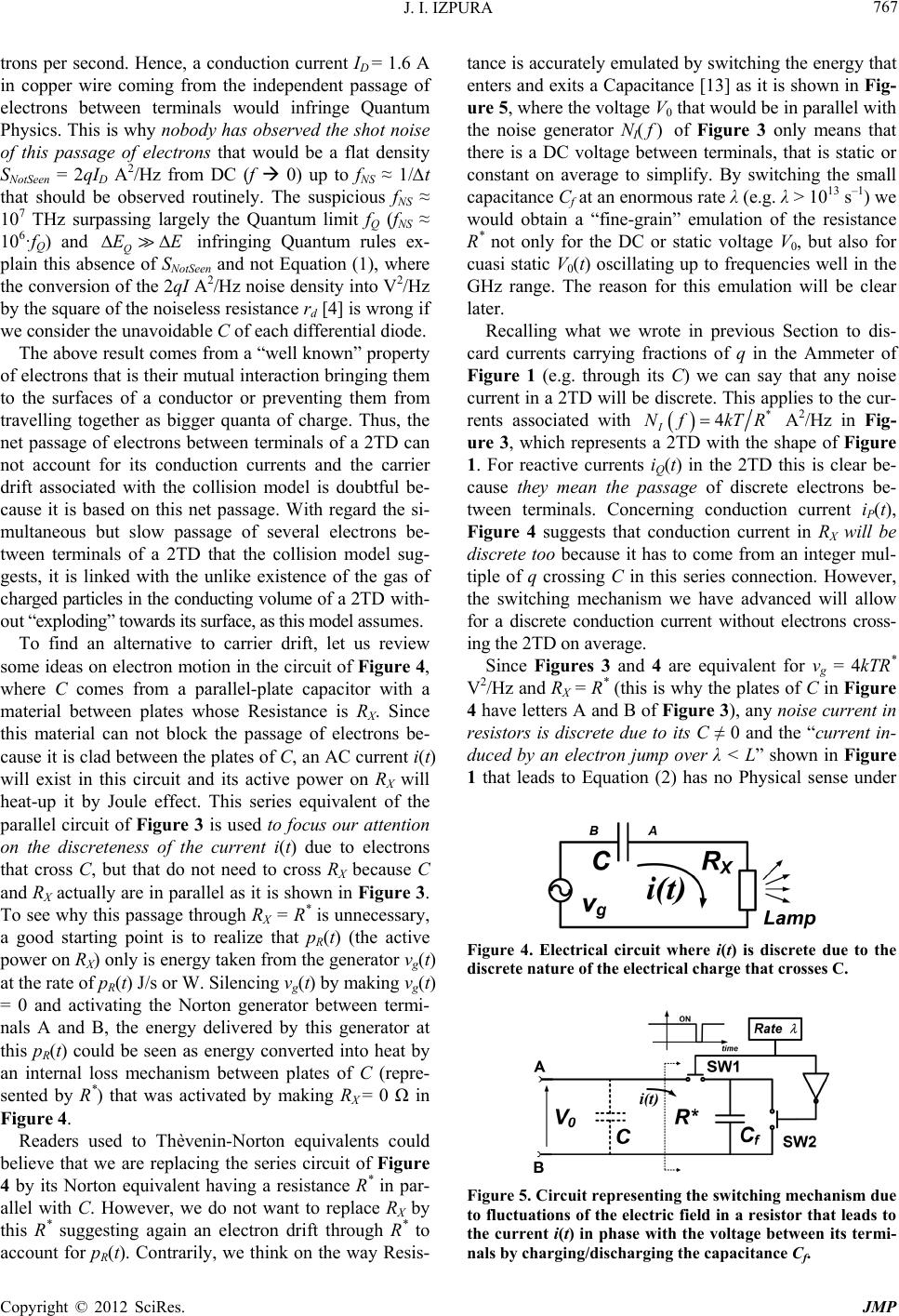 J. I. IZPURA 767 trons per second. Hence, a conduction current ID = 1.6 A in copper wire coming from the independent passage of electrons between terminals would infringe Quantum Physics. This is why nobody has observed the shot noise of this passage of electrons that would be a flat density SNotSeen = 2qID A 2/Hz from DC (f 0) up to fNS ≈ 1/∆t that should be observed routinely. The suspicious fNS ≈ 107 THz surpassing largely the Quantum limit fQ (fNS ≈ 106·fQ) and Q infringing Quantum rules ex- plain this absence of SNotSeen and not Equation (1), where the conversion of the 2qI A2/Hz noise density into V2/Hz by the square of the noiseless resistance rd [4] is wrong if we consider the unavoidable C of each differential diode. EE The above result comes from a “well known” property of electrons that is their mutual interaction bringing them to the surfaces of a conductor or preventing them from travelling together as bigger quanta of charge. Thus, the net passage of electrons between terminals of a 2TD can not account for its conduction currents and the carrier drift associated with the collision model is doubtful be- cause it is based on this net passage. With regard the si- multaneous but slow passage of several electrons be- tween terminals of a 2TD that the collision model sug- gests, it is linked with the unlike existence of the gas of charged particles in the conducting volume of a 2TD with- out “exploding” towards its surface, as this model assumes. To find an alternative to carrier drift, let us review some ideas on electron motion in the circuit of Figure 4, where C comes from a parallel-plate capacitor with a material between plates whose Resistance is RX. Since this material can not block the passage of electrons be- cause it is clad between the plates of C, an AC current i(t) will exist in this circuit and its active power on RX will heat-up it by Joule effect. This series equivalent of the parallel circuit of Figure 3 is used to focus our attention on the discreteness of the current i(t) due to electrons that cross C, but that do not need to cross RX because C and RX actually are in parallel as it is shown in Figure 3. To see why this passage through RX = R* is unnecessary, a good starting point is to realize that pR(t) (the active power on RX) only is energy taken from the generator vg(t) at the rate of pR(t) J/s or W. Silencing vg(t) by making vg(t) = 0 and activating the Norton generator between termi- nals A and B, the energy delivered by this generator at this pR(t) could be seen as energy converted into heat by an internal loss mechanism between plates of C (repre- sented by R*) that was activated by making RX = 0 Ω in Figure 4. Readers used to Thèvenin-Norton equivalents could believe that we are replacing the series circuit of Figure 4 by its Norton equivalent having a resistance R* in par- allel with C. However, we do not want to replace RX by this R* suggesting again an electron drift through R* to account for pR(t). Contrarily, we think on the way Resis- tance is accurately emulated by switching the energy that enters and exits a Capacitance [13] as it is shown in Fig- ure 5, where the voltage V0 that would be in parallel with the noise generator NI(f) of Figure 3 only means that there is a DC voltage between terminals, that is static or constant on average to simplify. By switching the small capacitance Cf at an enormous rate λ (e.g. λ > 1013 s–1) we would obtain a “fine-grain” emulation of the resistance R* not only for the DC or static voltage V0, but also for cuasi static V0(t) oscillating up to frequencies well in the GHz range. The reason for this emulation will be clear later. Recalling what we wrote in previous Section to dis- card currents carrying fractions of q in the Ammeter of Figure 1 (e.g. through its C) we can say that any noise current in a 2TD will be discrete. This applies to the cur- rents associated with * 4NfkTR I A 2/Hz in Fig- ure 3, which represents a 2TD with the shape of Figure 1. For reactive currents iQ(t) in the 2TD this is clear be- cause they mean the passage of discrete electrons be- tween terminals. Concerning conduction current iP(t), Figure 4 suggests that conduction current in RX will be discrete too because it has to come from an integer mul- tiple of q crossing C in this series connection. However, the switching mechanism we have advanced will allow for a discrete conduction current without electrons cross- ing the 2TD on average. Since Figures 3 and 4 are equivalent for vg = 4kTR* V2/Hz and RX = R* (this is why the plates of C in Figure 4 have letters A and B of Figure 3), any noise current in resistors is discrete due to its C ≠ 0 and the “current in- duced by an electron jump over λ < L” shown in Figure 1 that leads to Equation (2) has no Physical sense under Figure 4. Electrical circuit where i(t) is discrete due to the discrete nature of the electrical charge that crosses C. Figure 5. Circuit representing the switching mechanism due to fluctuations of the electric field in a resistor that leads to the current i(t) in phase with the voltage between its termi- nals by charging/discharging the capaci tance Cf. Copyright © 2012 SciRes. JMP 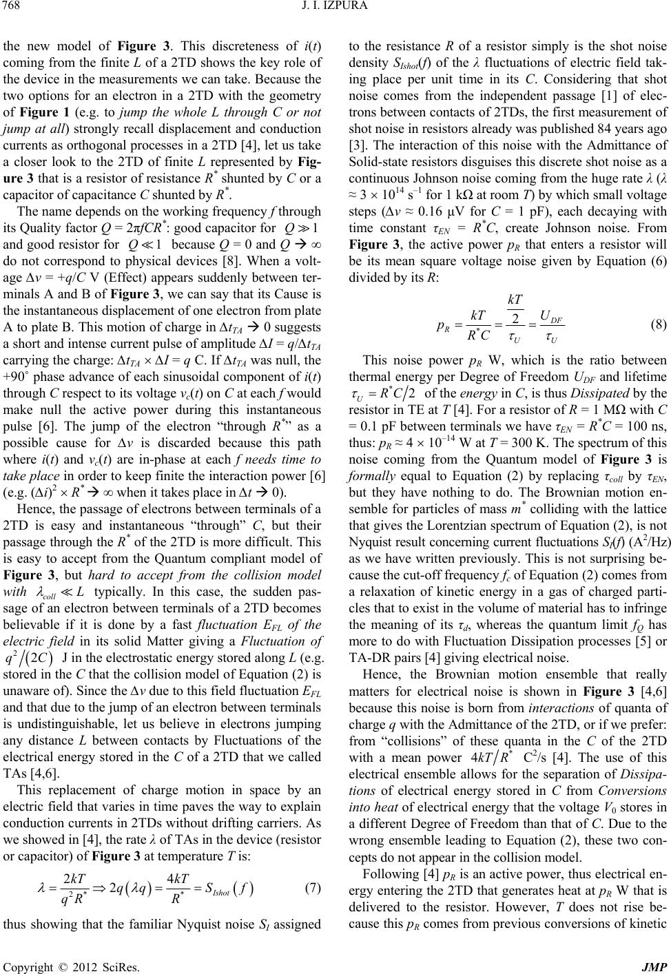 J. I. IZPURA 768 the new model of Figure 3. This discreteness of i(t) coming from the finite L of a 2TD shows the key role of the device in the measurements we can take. Because the two options for an electron in a 2TD with the geometry of Figure 1 (e.g. to jump the whole L through C or not jump at all) strongly recall displacement and conduction currents as orthogonal processes in a 2TD [4], let us take a closer look to the 2TD of finite L represented by Fig- ure 3 that is a resistor of resistance R* shunted by C or a capacitor of capacitance C shunted by R*. The name depends on the working frequency f through its Quality factor Q = 2πfCR*: good capacitor for and good resistor for because Q = 0 and Q ∞ do not correspond to physical devices [8]. When a volt- age ∆v = +q/C V (Effect) appears suddenly between ter- minals A and B of Figure 3, we can say that its Cause is the instantaneous displacement of one electron from plate A to plate B. This motion of charge in ∆tTA 0 suggests a short and intense current pulse of amplitude ∆I = q/∆tTA carrying the charge: ∆tTA ∆I = q C. If ∆tTA was null, the +90˚ phase advance of each sinusoidal component of i(t) through C respect to its voltage vc(t) on C at each f would make null the active power during this instantaneous pulse [6]. The jump of the electron “through R*” as a possible cause for ∆v is discarded because this path where i(t) and vc(t) are in-phase at each f needs time to take place in order to keep finite the interaction power [6] (e.g. (∆i)2 R* ∞ when it takes place in ∆t 0). 1Q 1Q L Hence, the passage of electrons between terminals of a 2TD is easy and instantaneous “through” C, but their passage through the R* of the 2TD is more difficult. This is easy to accept from the Quantum compliant model of Figure 3, but hard to accept from the collision model with coll typically. In this case, the sudden pas- sage of an electron between terminals of a 2TD becomes believable if it is done by a fast fluctuation EFL of the electric field in its solid Matter giving a Fluctuation of 22qC J in the electrostatic energy stored along L (e.g. stored in the C that the collision model of Equation (2) is unaware of). Since the ∆v due to this field fluctuation EFL and that due to the jump of an electron between terminals is undistinguishable, let us believe in electrons jumping any distance L between contacts by Fluctuations of the electrical energy stored in the C of a 2TD that we called TAs [4,6]. This replacement of charge motion in space by an electric field that varies in time paves the way to explain conduction currents in 2TDs without drifting carriers. As we showed in [4], the rate λ of TAs in the device (resistor or capacitor) of Figure 3 at temperature T is: * 4 Ishot S f 2* 2 2 kT kT qq qR R (7) thus showing that the familiar Nyquist noise SI assigned to the resistance R of a resistor simply is the shot noise density SIshot(f) of the λ fluctuations of electric field tak- ing place per unit time in its C. Considering that shot noise comes from the independent passage [1] of elec- trons between contacts of 2TDs, the first measurement of shot noise in resistors already was published 84 years ago [3]. The interaction of this noise with the Admittance of Solid-state resistors disguises this discrete shot noise as a continuous Johnson noise coming from the huge rate λ (λ ≈ 3 1014 s–1 for 1 kΩ at room T) by which small voltage steps (∆v ≈ 0.16 μV for C = 1 pF), each decaying with time constant τEN = R*C, create Johnson noise. From Figure 3, the active power pR that enters a resistor will be its mean square voltage noise given by Equation (6) divided by its R: * 2 F R UU kT U kT pRC (8) This noise power pR W, which is the ratio between thermal energy per Degree of Freedom UDF and lifetime *2RC U of the ene rgy in C, is thus Dissipated by the resistor in TE at T [4]. For a resistor of R = 1 MΩ with C = 0.1 pF between terminals we have τEN = R*C = 100 ns, thus: pR ≈ 4 10–14 W at T = 300 K. The spectrum of this noise coming from the Quantum model of Figure 3 is formally equal to Equation (2) by replacing τcoll by τEN, but they have nothing to do. The Brownian motion en- semble for particles of mass m* colliding with the lattice that gives the Lorentzian spectrum of Equation (2), is not Nyquist result concerning current fluctuations SI(f) (A2/Hz) as we have written previously. This is not surprising be- cause the cut-off frequency fc of Equation (2) comes from a relaxation of kinetic energy in a gas of charged parti- cles that to exist in the volume of material has to infringe the meaning of its τd, whereas the quantum limit fQ has more to do with Fluctuation Dissipation processes [5] or TA-DR pairs [4] giving electrical noise. Hence, the Brownian motion ensemble that really matters for electrical noise is shown in Figure 3 [4,6] because this noise is born from interactions of quanta of charge q with the Admittance of the 2TD, or if we prefer: from “collisions” of these quanta in the C of the 2TD with a mean power * 4kT R C 2/s [4]. The use of this electrical ensemble allows for the separation of Dissipa- tions of electrical energy stored in C from Conversions into heat of electrical energy that the voltage V0 stores in a different Degree of Freedom than that of C. Due to the wrong ensemble leading to Equation (2), these two con- cepts do not appear in the collision model. Following [4] pR is an active power, thus electrical en- ergy entering the 2TD that generates heat at pR W that is delivered to the resistor. However, T does not rise be- cause this pR comes from previous conversions of kinetic Copyright © 2012 SciRes. JMP 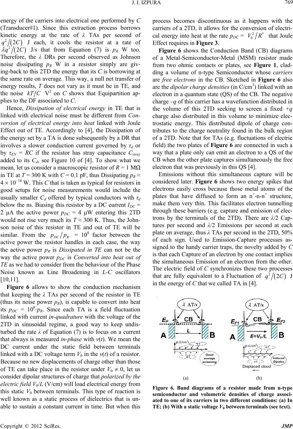 J. I. IZPURA 769 energy of the carriers into electrical one performed by C (Transducer#1). Since this extraction process borrows kinetic energy at the rate of λ TAs per second of 22qC J each, it cools the resistor at a rate of 22qC J/s that from Equation (7) is pR W too. Therefore, the λ DRs per second observed as Johnson noise dissipating pR W in a resistor simply are giv- ing-back to this 2TD the energy that its C is borrowing at the same rate on average. This way, a null net transfer of energy results, T does not vary as it must be in TE, and the noise kTC V 2 on C shows that Equipartition ap- plies to the DF associated to C. Hence, Dissipation of electrical energy in TE that is linked with electrical noise must be different from Con- version of electrical energy into heat linked with Joule Effect out of TE. Accordingly to [4], the Dissipation of the energy set by a TA is done subsequently by a DR that involves a slower conduction current governed by τd or by τEN = RC if the resistor has stray capacitance Cstray added to its Cd, see Figure 10 of [4]. To show what we mean, let us consider a macroscopic resistor of R = 1 MΩ in TE at T = 300 K with C = 0.1 pF, thus Dissipating pR ≈ 4 10–14 W. This C that is taken as typical for resistors in good setups for noise measurements would include the usually smaller Cd offered by typical conductors with τd below the ns. Biasing this resistor by a DC current IDC = 2 μA the active power pDC = 4 μW entering this 2TD would not rise very much its T ≈ 300 K. Thus, the John- son noise of this resistor in TE and out of TE will be similar. From the CR = 108 factor between the active power the resistor handles in each case, the way the active power pR is Dissipated in TE can not be the way the active power pDC is Converted into heat out of TE as we had to consider from the behaviour of the Phase Noise known as Line Broadening in L-C oscillators [10,11]. pp Figure 6 allows to show the conduction mechanism that keeping the λ TAs per second of the resistor in TE (thus its noise power pR), is capable to convert into heat its pDC = 108·pR. Since each TA is a field fluctuation linked with current in-quadra ture with the voltage of the 2TD in sinusoidal regime, a good way to keep undis- turbed the rate λ of Equation (7) is to focus on a current that always is measured in-phase with v(t). We mean the DC current under the static field between terminals linked with a DC voltage term V0 in the v(t) of a resistor. Because no new displacements of charge other than those of TE can take place in the resistor under V0 0, let us consider dipolar structures of charge that polarized by the electric field V0/L (V/cm) will load electrical energy from this static V0 between terminals. This type of reaction is well known as a static process of dielectrics that is un- able to sustain a constant current in time. But when this process becomes discontinuous as it happens with the carriers of a 2TD, it allows for the conversion of electri- cal energy into heat at the rate pDC = 2* 0 VR that Joule Effect requires in Figure 3. Figure 6 shows the Conduction Band (CB) diagrams of a Metal-Semiconductor-Metal (MSM) resistor made from two ohmic contacts or plates, see Figure 1, clad- ding a volume of n-type Semiconductor whose carriers are free electrons in the CB. Sketched in Figure 6 also are the dipolar charge densities (in C/cm3) linked with an electron in a quantum state (QS) of the CB. The negative charge –q of this carrier has a wavefunction distributed in the volume of this 2TD seeking to screen a fixed +q charge also distributed in this volume to minimize elec- trostatic energy. This distributed dipole of charge con- tributes to the charge neutrality found in the bulk region of a 2TD. Note that for TAs (e.g. fluctuations of electric field) the two plates of Figure 6 are connected in such a way that a plate only can emit an electron to a QS of the CB when the other plate captures simultaneously the free electron that was previously in this QS [4]. Emissions without this simultaneous capture will be considered later. Figure 6 shows two energy spikes that electrons easily cross because those metal atoms of the plates that have diffused to form an n+-n-n+ structure, make them very thin. This facilitates electron tunnelling through these barriers (e.g. capture and emission of elec- trons by the terminals of the 2TD). There are λ/2 Cap- tures per second and λ/2 Emissions per second at each plate on average, thus λ TAs per second in the 2TD, 50% of each sign. Used to Emission-Capture processes as- signed to the handy carrier traps, the novelty added by C is that each Capture of an electron by one contact implies the simultaneous Emission of an electron from the other. The electric field of C synchronizes these two processes that are fully equivalent to a Fluctuation of 22qC J in the energy of C that we called TA in [4]. (a) (b) Figure 6. Band diagrams of a resistor made from n-type semiconductor and volumetric densities of charge associ- ated to one of its carriers in two different conditions: (a) In TE; (b) With a static voltage V0 between terminals (see text). Copyright © 2012 SciRes. JMP  J. I. IZPURA 770 By symmetry, the average capture rate in each plate is λ/2 and when an electron of the CB is captured by one terminal, the extended wavefunction of its –q charge collapses into a wavefunction that localizes this charge on the surface of one plate (e.g. a TA takes place). Hence, those electrons forming carriers in the 2TD have two DF to attend: 1) being a long-range dipole between plates in each field fluctuation called TA, and 2) becoming a short-range, distributed dipole, in the volume of the 2TD (e.g. being a carrier in the CB). To attend these two DFs, the electron will switch in time between these states. Concerning emissions of electrons to an empty QS of the CB without a simultaneous capture by other plate, we will say that this “lonely emission” is typical from local defects as impurities for example. In this case the elec- tron arriving in the QS keeps an electrical link with the defect it leaves, thus being liable to be captured at a later time without needing a third element. This way, the elec- tron and the charged defect become the charges –q and +q linked by the electric field in a new device liable to give fluctuations in carrier flux, carrier number or in its mobility for example. Since this situation that recalls the electrical coupling between the filament of a vacuum tube and its surrounding electron cloud [14], has been studied recently to explain the flicker noise of electron fluxes in vacuum devices [8], we will not consider here this type of fluctuations that depart from the Fluctuations handled in [4-6]. Because V0 does not modify noticeably in Figure 6 the high field of the energy barriers, the contact resistances entering in the whole resistance R* of the resistor do not vary and this keeps λ, see Equation (7). This way, V0 or its current in-phase IDC do not change the rate λ of TAs and the Johnson noise of the device under V0 is similar to that in TE. By loading energy on each carrier that was proportional to (V0)2 and that was released as heat each time the free electron passed to form a TA, there would be a conversion of electrical energy into heat at a rate proportional to λ(V0)2. This means an active power pro- portional to 2* VR 0. Using Equation (7) to make it equal to the active power assigned to Joule effect, the energy Uf that each carrier would load from V0 would be [10]: 222 0 22 00 2 f f VqV U kT V 0 11 22 DC f T PU R qVC V (9) Thus, the reaction of each carrier as a small capaci- tance 2 CqkT f F loading energy from V0 and re- leasing it as heat each time it takes place in a TA, allows for the explanation of Joule effect without requiring car- rier drift and without changing the thermal noise the re- sistor had in TE. Thermal activity sustaining in time an imperfect screening between the charges +q and –q of each carrier would make it a thermal dipole of charges +q and –q on its plates liable to be polarized. This way, the electric field V0/L would see these carriers as trem- bling dipoles of charges +q and –q, each acting as an average capacitance Cf, that would become polarized as sketched in Figure 6. Thus, each carrier in the CB would be formed by a flabby cloud of charge –q distributed in the volume of the 2TD, aiming at screening as much as possible its portion of charge +q that would be a sort of rigid density of charge also distributed within this vol- ume. Although the exact form of these charge densities sketched in Figure 6(a) would depend on lattice atoms, doping, dislocations, etc. and on the Bloch functions de- fining the wavefunction of each electron within the de- vice, this shape is irrelevant here. What matters is to re- alize that carriers (free electrons in the CB) are not uni- polar charges liable to drift under the electric field due to V0 as point charges that, being negatively charged, would “explode” towards the surface. On the contrary, a free electron in the CB is captive in the bulk of the 2TD that hides its charge by the aforesaid screening required by charge neutrality. From time to time, this captive di- pole will show its charges on the surfaces (plates) of the 2TD. This will occur, each time its electron takes place in a TA or Fluctuation of electric field in the 2TD. This way, the electron continues captive in the 2TD, but looking freer in another Degree of Freedom less sub- jected to the rigorous law of charge neutrality prevailing in the bulk. Polarization loading Uf on each carrier will be a fast process for conductors (recall the meaning of d ) and since the support of Uf in the volume of the device will disappear each time the carrier appears on the plates in a TA, this Uf will be released as phonons to the vol- ume of the 2TD. This release will be accomplished by the synchronous shaking of the lattice at different posi- tions (e.g. those shown by a small cross in Figure 6) tak- ing place each time the flabby cloud exerting force on these points disappears in the TA. In summary: the re- lease of the energy Uf loaded by a carrier from 0 in a resistor is triggered by each Fluctuation of this field that implicates this carrier. This replaces drifting charges by interacting fields and explains how to convert electri- cal energy into heat without carriers drifting in Solid Matter. VL Although a TA occurs instantaneously, its associated energy requires some time ∆tTA to appear in the 2TD to keep finite the power of this Fluctuation (see a paradox appearing when one uses naively an infinite interaction power [6]). To consider the non null ∆tTA that a carrier needs to carry out the TA in which it is implicated, let us use the same TEUP we used to discard carrier drift. Re- Copyright © 2012 SciRes. JMP  J. I. IZPURA 771 calling the meaning of System 0, the minimum time in- terval ∆tTA required to define the energy 22Eq C of the System0 for each TA would be: TATA 2 2 Ett q K CRC (10) where RK is link with the Quantum Hall Resistance we found in [15] looking for a metrological interest of the discrete resistance proposed in [4]. Before reading [15] we considered RK as the lowest possible resistance per carrier of a 2TD giving the maximum active power per carrier in it. This appears by considering the highest rate of TAs in a 2TD with only one carrier that would be: λQ = 1 1 st TA if the ∆E set in C by each TA disappeared instantaneously. Since a TA is the Cause that sets vqC V in the 2TD (Effect) we can take ∆v as the average voltage in C during ∆tTA. If the energy ∆E was removed by the arrival of the next TA, the active power sustaining in time the static voltage ∆v in C would be: 2 2 222 22 QQ v q C R qq PCC (11) Equation (11) means that PQ is the active power that enters the Conductance 12GR QK driven by the continuous voltage ∆v sustained in this way. Thus, GQ would be the highest Conductance of a 2TD like that of Figure 1 with only one carrier in its volume, due to the maximum rate of TAs in its capacitance C. However, Figure 7(a) shows the outer capacitance C of this 2TD due to charge densities induced by each TA on the ex- ternal faces of its plates of σ ∞ under the open-circuit condition that exists for an instantaneous TA due to the inductance of external wires. In the 1-D model at hand, the magnitude of electric field at points a, b, b’ and a’ of Figure 7(a) is the same because the charge density on each surface has the same magnitude. Since the plates are equipotential, the voltage drop going from point a on plate A to point b on plate B will be equal to the voltage drop going from point b’ to point a’ on the outer surfaces. Hence, each TA sets ∆E in the inner C and ∆E in the outer C, thus 2 True EqC J in all, which is the en- ergy of two parallel sheets of charges +q and –q sepa- rated by a distance L. This is the “electrical image of a TA” that appears in Figure 7(b) together with its fluc- tuation of electric field 0 LDev Using ∆ETrue in Equations (10) and (11) the active power needed to sustain the static voltage ∆v in C be- comes: ptrue = 4pQ. Connecting a generator to this 2TD, the outer C of Figure 7(a) becomes the capacitance of the new 2TD that the generator is. Given the opposed signs of reactive currents in the inner and outer C from the generator viewpoint, this generator would be deliver- ing an active power ptrue = 4pQ while absorbing 2pQ due to its role as inner C. Therefore, this generator would be delivering an active power Pmeas = 2pQ W to sustain ∆v. Thus, the lowest resistance per carrier that a 2TD can offer is RK. EqA . Equipartition theorem also must apply to the DF that Cf represents. For an electron emitted to the lowest en- ergy level of the CB, the first image of its dipolar charge would show its –q cloud closely wrapped around its +q array, good average screening of Figure 6(a). This is a very cold carrier that interacting thermally will pass to show the mean thermal energy2 J in TE by an imperfect screening between its +q and –q charges varying randomly with time around its minimum value. Viewing this trembling dipole as two charges +q and –q separated by a distance d(t) varying with time, each car- rier is thus a capacitance CF(t) ovalue kT f mean F Ct “built” by the av energy erage2kT J set by Equiparti- tion in this DF linked with carrier polarization. Therefore, CF(t) should fluctuate around this F Ct: mean value 22 2 22 2 f FT F kTqqq q CC CtkTV Ct (12) Hence, the mean capacitance F set by Equi- partition for each carrier in TE is the Cf that Equation (9) needs to account for Joule Effect out of TE by carrier polarization. Loading energy from V0 in Cf and releasing it to the lattice as heat each time a TA takes place, the active power Ct CR is converted into heat without requiring carriers colliding within the 2TD. Since this pDC will try to heat-up the resistor out of TE due to its V0 0, we are assuming a good extraction of this heat to keep T close to its value for V0 = 0 in order to keep its noise of TE. This new model for the familiar Joule effect departs markedly from the one we had accordingly to the microscopic view of Ohm’s law given in [12] that is based on carriers drifting under the action of the field pp 0 The deep rooted character of this idea on electrical VL . (a) (b) Figure 7. (a) 1-D sketch of electric field and charge densities associated with a thermal action in a 2TD having two ideal- ized terminals (see text); (b) 1-D sketch of electric field and dipolar charge associated with a fluctuation of electric field EFL taking place in a real 2TD (e.g. a thermal action). Copyright © 2012 SciRes. JMP  J. I. IZPURA 772 conduction requiring “carrier motion in space” can be seen in Section 2.3 of [16] by these phrases: “The basic physical fact to be borne in mind when discussing polarisation is that polarisation arises from a finite displacement of charges in a steady electric field and this is to be contrasted with the complementary physical phenomenon of electrical conduction which is characterised by the fact that conduction arises from a finite average velocity of motion of charges in a steady electric field.” After these sentences, we also can read this one about polarising species “…which are incapable of leading to a continuing conduction current in a static field” [16] (except for enormous fields ≈ 1010 - 1011 V/m breaking dipoles that we will not consider here). Working with noise, “static” is more the exception than the rule and switching mechanisms making devices work are familiar. Transformers unable to work under a static or DC voltage V0, perform well if the voltage V0 is switched in time and a capacitance Cf that is charged and discharged at a high rate λ can emulate very convincingly a Resistance R* by the conversion of electrical power into heat that takes place in Figure 5, where the active power pDC leaving the generator V0 towards its switched emula- tor of R*, simply is λ times the energy loaded in Cf: pDC = 22CV 0 J/s or W. To emulate R* = 1 kΩ by the small capacitance Cf of a single carrier in the resistor of Figure 5 at T = 300 K, the required rate is given by Equation (7): λ ≈ 3 1014 commutations per second. This is a high rate that could conflict with the TEUP, but di- viding λ by the huge number of carriers (parallel chan- nels) that exist in typical 2TDs, no conflict appears. With λ ≈ 3 1014 s–1, the active power * pVR 0 DC that leaves the generator V0 in Figure 5 is exactly equal to the active power converted into heat by a resistor of R* = 1 kΩ driven by V0. The inverter of Figure 5 guarantees two excluding states for switches SW1 and SW2 emulat- ing the two excluding states of the electron in Figure 5: 1) free carrier in the volume (SW1 ON, SW2 OFF) or 2) long range dipole on the terminals (SW2 ON, SW1 OFF). When SW1 becomes ON, the carrier loads its Cf with 22UCV 0ff in a time interval ∆tload ≈ τd. This Uf remains in Cf until the next TA implicating this electron because this circuit does not have resistances other than R* emulated in this way. Concerning the way active power leaves R* we will say that closing briefly SW2 during ∆tTA the energy Uf leaves Cf as heat “in the wire” of SW2. However, the null resistance of this wire hardly would convert electrical energy into heat at first sight. The problem can be solved by considering this wire as a very low inductance LS 0. This would lead to an L-Cf resonant circuit of resonance frequency f0 ∞ giving a high enough number of periods during ∆tTA so as to radi- ate all the energy Uf that was in Cf. This way, Uf would leave Cf converted into a different type of energy. After the brief ∆tTA, SW1 would become ON and Cf would acquire another packet of energy Uf. Repeating the “TA state” (SW1 OFF, SW2 ON) λ times per second, an ac- tive power 2* R 0DC pV would be converted into photons and radiated by the L-Cf circuit. The “radiation resistance” of this switched LS-Cf tank would emulate the continuous resistance of *2 RC Ω that seems to be connected to the generator V0 due to the pDC it delivers in an ultrafast switched mode that looks continuous as Ohm’s Law considers. For switching rates like λ ≈ 3 1014 s–1 the current i(t) of Figure 5 looks like DC (e.g. continuous) and if V0 was a quasi-static voltage of amplitude V0 oscillating at 100 MHz for example, the current i(t) would track closely V0 as a sinusoidal current of amplitude * R 0 V A at 100 MHz that would be “totally” in-phase with V0(t). This would be so because the period T0 = 10 ns is a time window for 3 105 TAs. Due to this huge switching rate the Phase uncertainty would be of the order of 5 1310 f rad [11]. Unaware of the discreteness of i(t) and unable to measure a relative phase with this degree of accuracy, we would think of this current as the conduction current of electrons drifting through a “continuous” resistor of R* = 1 kΩ driven by V0 oscillating at 100 MHz. The novelty is that R* is a discrete series of λ chances in time to convert electrical energy into another form. This idea has been used to explain Phase Noise in L-C oscillators [10,11]. The behaviour of carriers as distributed dipoles added to their need to appear as charges on the terminals of a 2TD from time to time, lead to show that the generation of heat by Joule Effect comes from a Switched Current (SC) that looks totally in phase with any AC voltage V0(t) on the 2TD for frequencies . This limit however, will be lower in general: N f, due to the cut-off frequency 12πf ENEN of the circuit of Figure 3. This lower limit set by the Admitance of the 2TD further disguises this SC as “continuous current” or DC. This recalls the action of this Admittance on the shot noise of TAs disguising them as a continuous Johnson noise. Re- calling words about “the complementary physical phe- nomenon of electrical conduction” [16] respect to static polarization, let us say that discrete charges that cross the 2TD as a mean current Q = IDC in capacitive devices produce its familiar shot noise Sshot = 2qIDC A2/Hz whereas carriers that do not cross the 2TD are capable however, to emulate a mean current it P = IDC in-phase with its voltage v(t) that is noiseless. it Finally let us say that this model explains well why the Phase Noise of an L-C oscillator is reduced as its Signal power rises provided its T raise is low. Unaware about the difference between Dissipation of energy and its Conversion into heat, an increase of the active power (Signal power) in the resonator of an oscillator would increase its Dissipation of energy and thus, its Noise Copyright © 2012 SciRes. JMP  J. I. IZPURA Copyright © 2012 SciRes. JMP 773 REFERENCES power by the same factor. This way, the Phase Noise would not decrease by increasing the Signal power be- cause the Signal/Noise power ratio would not change either. Hence, the decrease of Phase Noise in L- C oscil- lators as their Signal power rises is an added proof for this conduction model where carriers do not drift either in the resistor embedded in their L-C resonators [10,11]. [1] J. B. Johnson, “The Schottky Effect in Low Frequency Circuits,” Physical Review Letters, Vol. 26, No. 1, 1925, pp. 71-85. doi:10.1103/PhysRev.26.71 [2] W. Schottky, “Small-Shot Effect and Flicker Effect,” Physical Review, Vol. 28, No. 6, 1926, pp. 74-103. doi:10.1103/PhysRev.28.1331 [3] J. B. Johnson, “Thermal Agitation of Electricity in Con- ductors,” Physical Review, Vol. 32, No. 1, 1928, pp. 97- 109. doi:10.1103/PhysRev.32.97 4. Conclusions Electrical noise and electrical conduction are linked with the electrical voltage measured simultaneously between the two terminals of a device whose capacitance C plays a key role in the origin of this voltage. Due to the dis- creteness of electric charge, C quantizes the currents in the device so as to produce discrete Fluctuations of elec- trical energy that are equivalent to the jump of an elec- tron between terminals of C. This defines the thermal action or Fluctuation of electric field in C (EFL) that is the Cause of a subsequent device reaction (Effect) that Dis- sipates the energy [4] J. I. Izpura and J. Malo, “A Fluctuation-Dissipation Model for Electrical Noise,” Circuits and Systems, Vol. 2, No. 3, 2011, pp. 112-120. doi:10.4236/cs.2011.23017 [5] H. B. Callen and T. A. Welton, “Irreversibility and Gen- eralized Noise,” Physical Review, Vol. 83. No. 1, 1951, pp. 34-40. doi:10.1103/PhysRev.83.34 [6] J. I. Izpura, “Revisiting the Classics to Recover the Physi- cal Sense in Electrical Noise,” Journal of Modern Physics, Vol. 2, No. 6, 2011, pp. 457-462. doi:10.4236/jmp.2011.26055 22Eq C J set by the TA. [7] H. Nyquist, “Thermal Agitation of Electric Charge in Conductors,” Physical Review, Vol. 32, No. 1, 1928, pp. 110-113. doi:10.1103/PhysRev.32.110 Carriers in Solid State resistors are distributed dipoles loading electrical energy Uf from the electric field exist- ing in these devices. This Uf is thus stored in the volume of the device, not in C. When a TA takes place, one of these carriers collapses into a long-range dipole between terminals that stores a Fluctuation ∆E in C due to the displaced charge. This ∆E is borrowed from the kinetic energy of the carrier and the energy Uf that was loaded on this carrier is released uniformly as heat to the volume that defines the [8] J. I. Izpura, “On the Electrical Origin of Flicker Noise in Vacuum Devices,” IEEE Transactions on Instrumenta- tion and Measurement, Vol. 58, No. 10, 2009, pp. 3592- 3601. doi:10.1109/TIM.2009.2018692 [9] J. I. Izpura, “1/f Electrical Noise in Planar Resistors: The Joint Effect of a Backgating Noise and an Instrumental Disturbance,” IEEE Transactions on Instrumentation and Measurement, Vol. 57, No. 3, 2008, pp. 509-517. doi:10.1109/TIM.2007.911642 1GR of the device. Only the energy ∆E stored by each TA in C is Dissipated by the DR that is a relaxation of energy with lifetime [10] J. I. Izpura and J. Malo, “Thermodynamical Phase Noise in Oscillators Based on L-C Resonators (Foundations),” Circuits and Systems, Vol. 3, No. 1, 2012, pp. 48-60. doi:10.4236/cs.2012.31008 *2RC U The Conversion of electrical energy into heat (Joule Effect) is a process that involves carriers, but it does not require displacement currents other than those that al- ready existed when the 2TD was in TE. If temperature raise is small, this conversion process does not add shot noise to the shot noise that appears disguised as Johnson noise in resistors or as . [11] J. Malo and J. I. Izpura, “Thermodynamical Phase Noise in Oscillators Based on L-C Resonators,” Circuits and Systems Vol. 3, No. 1, 2012, pp. 61-71. doi:10.4236/cs.2012.31009 kTC noise in capacitors. This Conversion of energy into heat that differs from its Dis- sipation in electrical noise also explains why Phase Noise in L-C oscillators decreases as their Signal Power is in- creased. This model where the classical Resistance is discrete in time shows the capacitive link that exists be- tween this Resistance and the Quantum Resistance 2 q K that would be the lowest possible resistance per carrier in a two-terminal device. [12] R. Nave, “Microscopic View of Ohm’s Law,” 2005. http://hyperphysics.phy-astr.gsu.edu/hbase/electric/ohmm ic.html [13] http://en.wikipedia.org/wiki/Switched_capacitor [14] I. Langmuir, “The Effect of Space Charge and Initial Velocities on the Potential Distribution and Thermionic Current between Parallel Plane Electrodes,” Physical Re- view, Vol. 21, No. 4, 1923, pp. 419-435. doi:10.1103/PhysRev.21.419 R [15] F. Overney, B. Jeanneret, B. Jeckelmann, B. M. Wood and J. Schurr, “The Quantized Hall Resistance: Towards a Primary Standard of Impedance,” Metrologia, Vol. 43, No. 5, 2006, pp. 409-413. doi:10.1088/0026-1394/43/5/011 5. Acknowledgements Work supported by the Spanish CICYT under the MAT- 2010-18933 project, by the Comunidad Autónoma de Madrid through its IV-PRICIT Program and by the pro- ect N˚ 304814 RAPTADIAG of the E.U. [16] A. K. Jonscher, “Dielectric Relaxation in Solids,” Chelsea Dielectrics Press Ltd., London, 1983. j
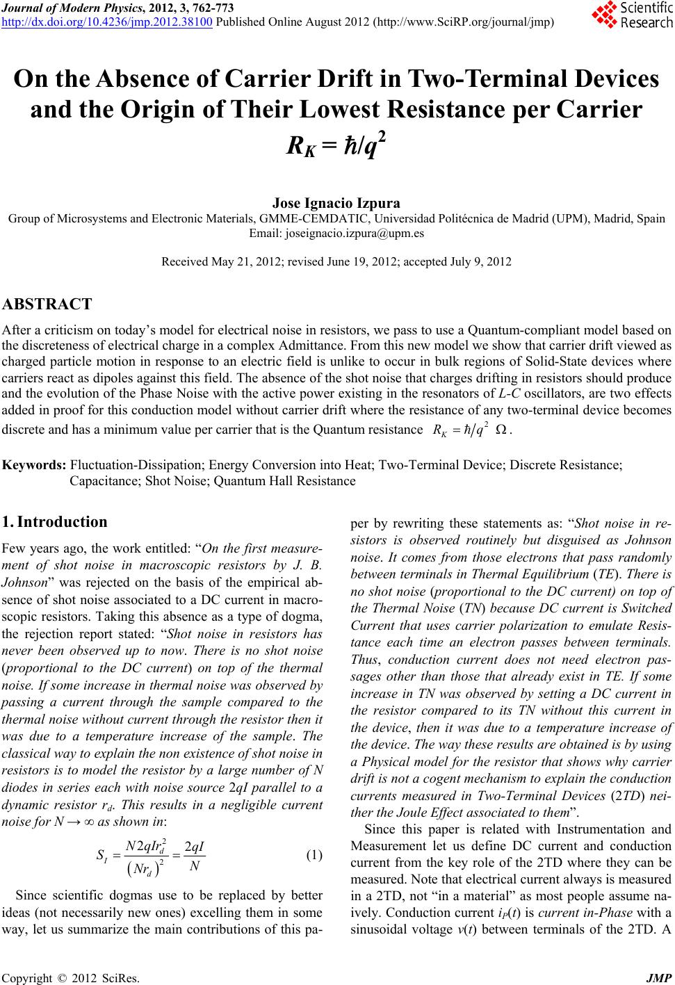
|