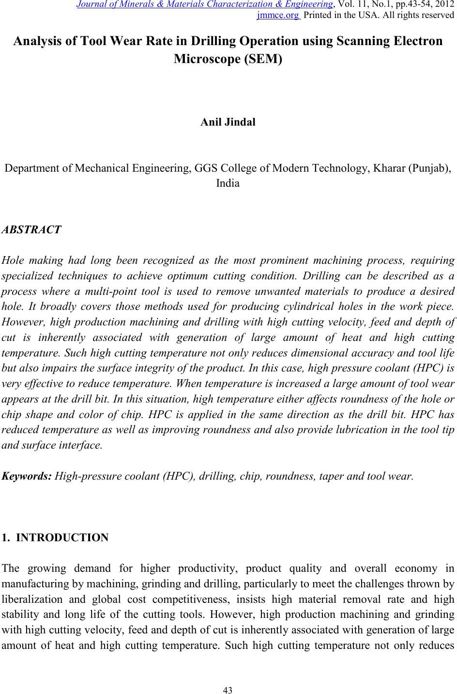
 Journal of Minerals & Materials Characterization & Engineering, Vol. 11, No.1, pp.43-54, 2012 jmmce.org Printed in the USA. All rights reserved 43 Analysis of Tool W ear R ate in Drilling Operation using Scanning Electron Microscop e (SE M) Anil Jindal Department of Mechanical Engineering, GGS College of Modern Technology, Kharar (Punjab), India ABSTRACT Hole making had long been recognized as the most prominent machining process, requiring specialized techniques to achieve optimum cutting condition. Drilling can be described as a process where a multi-point tool is used to remove unwanted materials to produce a desired hole. It broadly covers those methods used for producing cylindrical holes in the work piece. However, high production machining and drilling with high cutting velocity, feed and depth of cut is inherently associated with generation of large amount of heat and high cutting temperature. Such high cutting temperature not only reduces dimensional accuracy and tool life but also impairs the surf ace integrity of the produ ct. In this case, high pressure coolant (HPC ) is very ef fect ive t o r educe tem pera tu re. When temper at ure i s in creased a large amount of tool wear appears at the drill bit. I n this situation, hi gh temperature either affects ro undness of the hole or chip shape and color of chip. HPC is applied in the same direction as the drill bit. HPC has reduced temperature as well as improving roundness and also provide lubrication in t he tool tip and surface interface. Keywords: High-pressure coolant (HPC), drilling, chip, roundness, taper and tool wear. 1. INTRODUCTION The growing demand for higher productivity, product quality and overall economy in manufacturing by machini ng, grinding and drilling, particularl y to meet the challenges thrown by liberalization and global cost competitiveness, insists high material removal rate and high stability and long life of the cutting tools. However, high production machining and grinding with high cutting velocity, feed and depth of cut i s inherently associated with generation of large amount of heat and high cutting temperature. Such high cutting temperature not only reduces 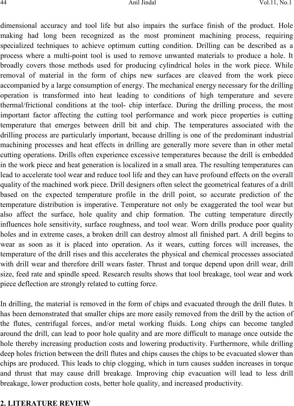 44 Anil Jindal Vol.11, No.1 dimensional accuracy and tool life but also impairs the surface finish of the product. Hole making had long been recognized as the most prominent machining process, requiring specialized techniques to achieve optimum cutting condition. Drilling can be described as a process where a multi-point tool is used to remove unwanted materials to produce a hole. It broadly covers those methods used for producing cylindrical holes in the work piece. While removal of material in the form of chips new surfaces are cleaved from the work piece accompanied by a large consumption of energy. The mechanical energy necessary for the drilling operation is transformed into heat leading to conditions of high temperature and severe thermal/frictional conditions at the tool- chip interface. During the drilling process, the most important factor affecting the cutting tool performance and work piece properties is cutting temperature that emerges between drill bit and chip. The temperatures associated with the drilling process are particularly important, because drilling is one of the predominant industrial machining processes and heat effects in drilling are generally more severe than in other metal cutting operations. Drills often experience excessive temperatures because the drill is embedded in the work piece and heat gener ation is lo caliz ed in a s mall area. Th e resu lti ng temperat ures can lead to accelerate tool wear and reduce tool life and they can have profound effects on the overall quality of the machined work piece. Drill designers often select the geometrical features of a drill based on the expected temperature profile in the drill point, so accurate prediction of the temperature distribution is imperative. Temperature not only be exaggerated the tool wear but also affect the surface, hole quality and chip formation. The cutting temperature directly influences hole sensitivity, surface roughness, and tool wear. Worn drills produce poor quality holes and in extreme cases, a broken drill can destroy almost all finished part. A drill begins to wear as soon as it is placed into operation. As it wears, cutting forces will increases, the temperature of the drill rises and this accelerates the physical and chemical processes associated with drill wear and therefore drill wears faster. Thrust and torque depend upon drill wear, drill size, feed rate and spindle speed. Research results shows that tool breakage, tool wear and work piece deflection are strongly related to cutting force. In drilling, the material is removed in the form of chips and evacuated through the drill flutes. It has been demonstrated th at small er chips are mo re easily removed from the drill by the action of the flutes, centrifugal forces, and/or metal working fluids. Long chips can become tangled around the drill, can lead to poor hole quality and are more difficult to manage once outside the hole thereby increasing production costs and lowering productivity. Furthermore, while drilling deep holes friction between the drill flutes and chips causes the chips to be evacuated slower than chips are produced. This leads to chip clogging, which in turn causes sudden increases in torque and thrust that may cause drill breakage. Improving chip evacuation will lead to less drill breakage, lower production costs, better hole quality, and increased productivity. 2. LITERATURE REVIEW 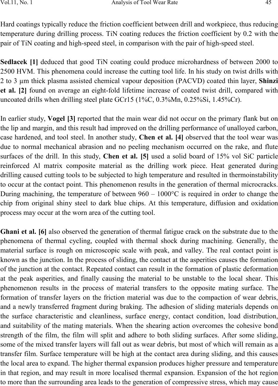 Vol.11, No. 1 Analysis of Tool Wear Rate 45 Hard coatings typically reduce the friction coefficient between drill and workpiece, thus reducing temperature during drilling process. TiN coating reduces the friction coefficient by 0.2 with the pair of TiN coating and high-speed steel, in comparison with the pair of high-speed steel. Sedlacek [1] deduced that good TiN coating could produce microhardness of between 2000 to 2500 HVM. This phenomena could increase the cutting tool life. In his study on twist drills with 2 to 3 µm thick plasma assisted chemical vapour deposition (PACVD) coated thin layer, Shinzi et al. [2] found on average an eight-fold lifetime increase of coated twist drill, compared with uncoated drills when drilling steel plate GCr15 (1%C, 0.3%Mn, 0.25%Si, 1.45%Cr). In earlier study, Vogel [3] reported that the main wear did not occur on the primar y flank but on the lip and margin, and this result had improved on the drilling performance of unalloyed carbon, case hardened, and tool steel. In another study, Chen et al. [4] observed that the tool wear was due to normal mechanical abrasion and no peeling mechanism occurred on the rake, and flute surfaces of the drill. In this study, Chen et al. [5] used a solid board of 15% vol SiC particle reinforced Al matrix composite material as the drilling work piece. Heat generated during drilling caused cutting tools to be subjected to hi gh temperature and resulted i n thermoinstability to occur at the contact point. This phenomenon results in the generation o f thermal mi crocracks. During machining, the temperature of between 960 – 1000°C is required in order to change the chip from original shiny steel to dark blue chips. At this temperature, diffusion and oxidation process may occur at the worn area of the cutting tool. Ghani et al. [6] also observed the generation of thermal fatigue crack on the substrate due to the phenomena of thermal cycling, coupled with thermal shock during machining. Generally, the material surface is rough on microscopic scale with peak, and valley. The real contact point is known as the junction. In the process o f slidin g, the contact at the asperities causes the formation of the junction at the cont act. Repeated contact can result in the formation of plastic deformation at the peak asperities, and finally causing the material to be unstable to the local shear. This phenomenon results in the process of material transfers to the opposite mating surface. The formation of transfer layers on the friction material was due to the compaction of wear debris, and a newly transferred fragment during braking. The adhesion of sliding materials depends on the surface characteristic and cleanliness, surface energy, contact condition, load distribution, and suitability of the mating materials. When the shearing action overcomes the cohesive bond strength of the film, the film will split and adhere to both sliding surfaces. After some sliding, some of the mixed transfer layers will fall out as wear debris, but most of which will remain as a transfer fi lm. Surface t emperatur e will be hi gh at the contact a rea during s liding, and t his causes the local area to expand. The higher thermal expansion produces higher pressure and temperature in that region, and may result in more localised thermal expansion. Expansion of the hot region to more than the surrounding area leads to the generation of compressive stress, which may cause 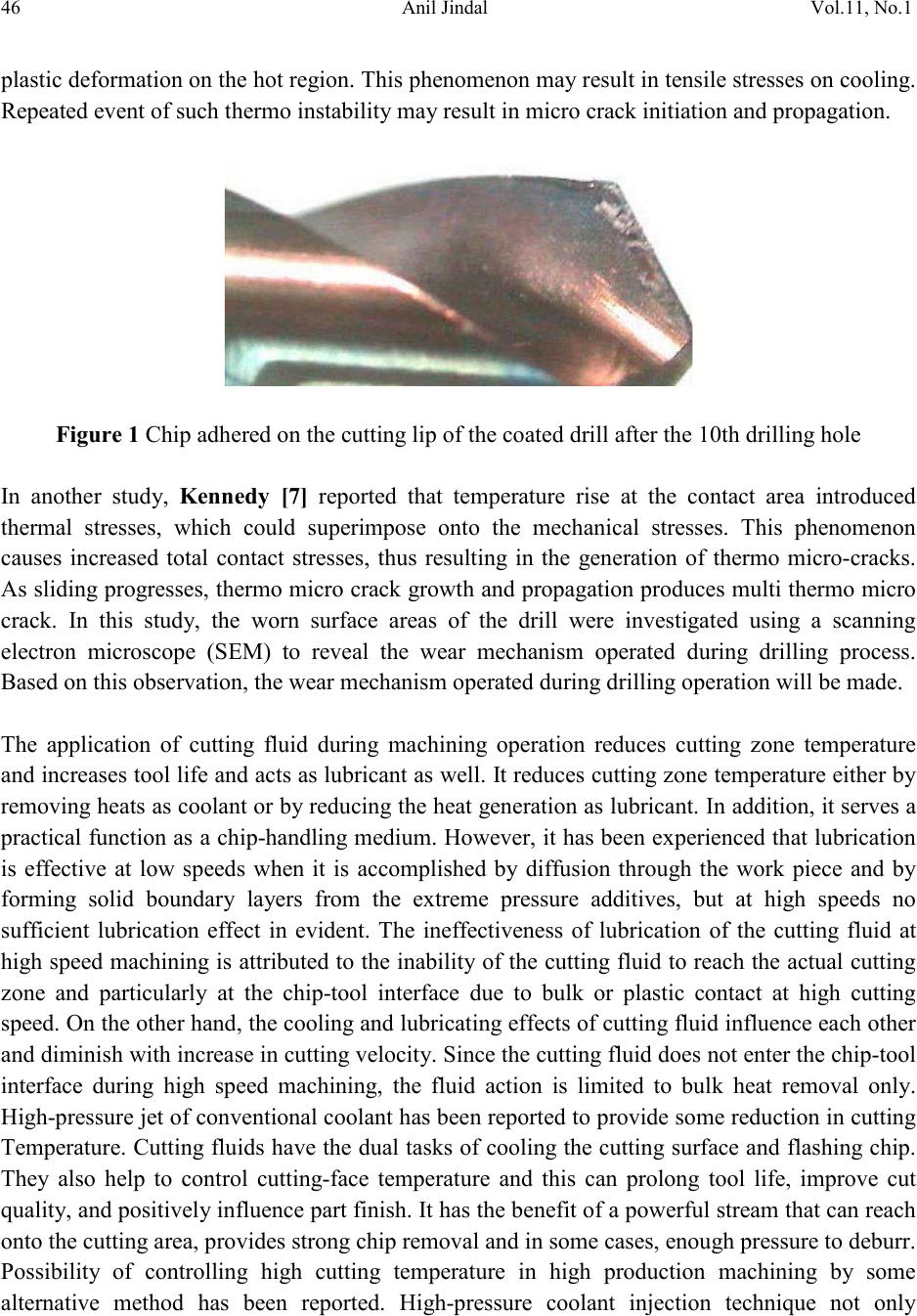 46 Anil Jindal Vol.11, No.1 plastic deformation on the hot region. This phenomenon may result in tensile stresses on cooling. Repeated event of such thermo instability may result in micro crack initiation and propagation. Figure 1 Chip adhered on the cutting lip of the coated drill after the 10th drilling hole In another study, Kennedy [7] reported that temperature rise at the contact area introduced thermal stresses, which could superimpose onto the mechanical stresses. This phenomenon causes increased total contact stresses, thus resulting in the generation of thermo micro-cracks. As sliding progresses, thermo micro crack growth and propagation produces multi thermo micro crack. In this study, the worn surface areas of the drill were investigated using a scanning electron microscope (SEM) to reveal the wear mechanism operated during drilling process. Based on this observation, the wear mechanism operated during drilling operation will be made. The application of cutting fluid during machining operation reduces cutting zone temperature and increas es too l life and act s as lubr icant as well . It reduces cutting z one tem perature eith er by removing heats as coolant or by reducing the heat generation as lubricant. In addition, it serves a practical function as a ch ip-handling medium. Ho wever, it has been experienced that lubrication is effective at low speeds when it is accomplished by diffusion through the work piece and by forming solid boundary layers from the extreme pressure additives, but at high speeds no sufficient lubrication effect in evident. The ineffectiveness of lubrication of the cutting fluid at high speed machining is attributed to the inability of the cutting fluid to reach the actual cutting zone and particularly at the chip-tool interface due to bulk or plastic contact at high cutting speed. On the other hand, the cooling and lubricating effects of cutting fluid influence each other and diminish with increase in cutting velocit y. Since the cutting fluid does not enter the chip-tool interface during high speed machining, the fluid action is limited to bulk heat removal only. High-pressure jet of conventional coolant has bee n reported to provide some reduction in cutting Temperature. Cutting fluids have the dual tasks of cooling the cutting surface and flashing chip. They also help to control cutting-face temperature and this can prolong tool life, improve cut quality, and positivel y influence part finish. It has the b enefit of a pow erful st ream that can reach onto the cutting area, provides strong chip removal and in some cases, enough pressure to deburr. Possibility of controlling high cutting temperature in high production machining by some alternative method has been reported. High-pressure coolant injection technique not only 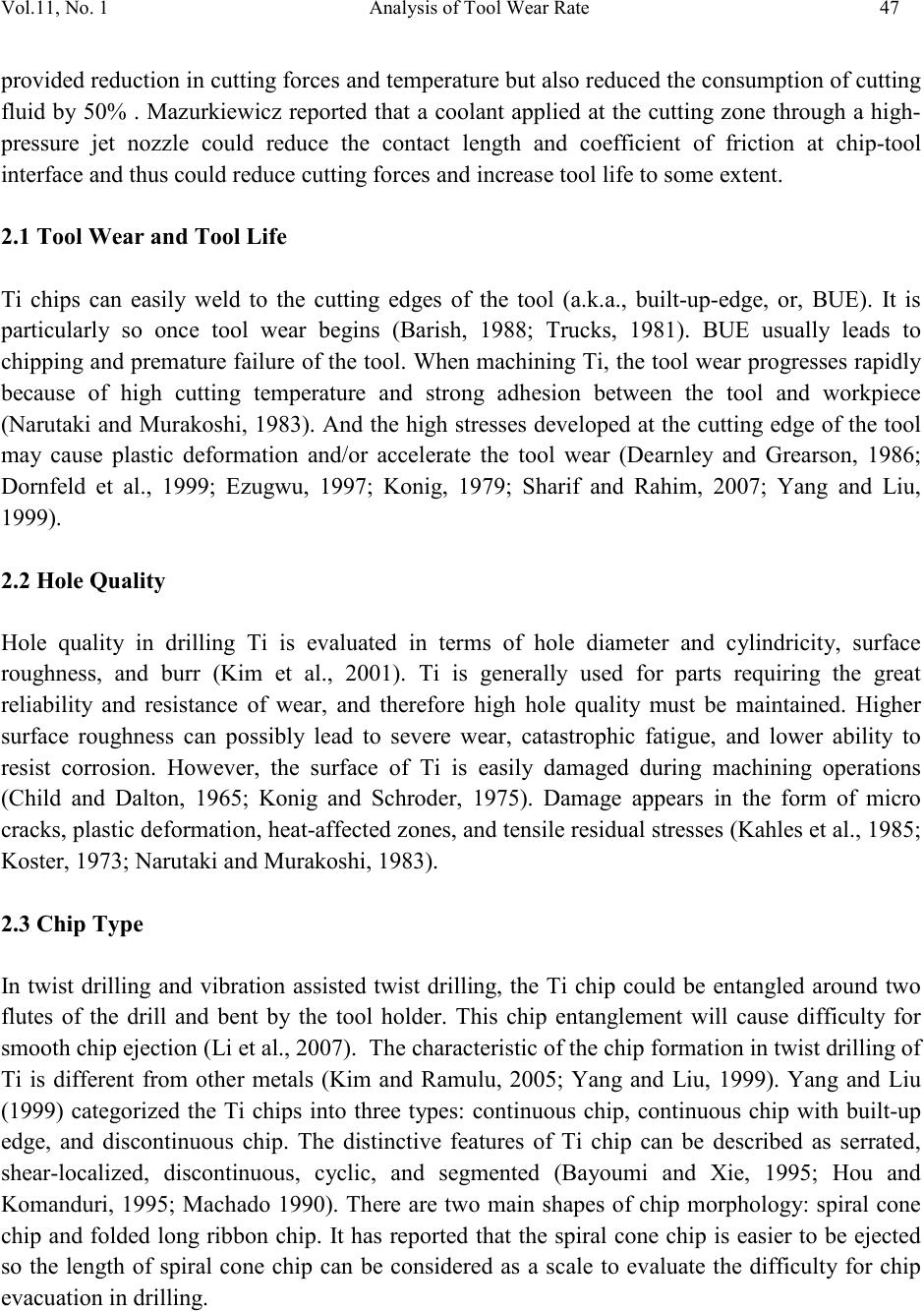 Vol.11, No. 1 Analysis of Tool Wear Rate 47 provided reduction in cutting forces and temperature but also reduced the consum ption of cutting fluid by 50% . Mazurkiewicz reported that a coolant applied at the cutting zone through a high- pressure jet nozzle could reduce the contact length and coefficient of friction at chip-tool interface and thus could reduce cutting forces and increase tool life to some extent. 2.1 Tool Wear and Tool Life Ti chips can easily weld to the cutting edges of the tool (a.k.a., built-up-edge, or, BUE). It is particularly so once tool wear begins (Barish, 1988; Trucks, 1981). BUE usually leads to chipping and premature failure of the tool. When machining Ti, the tool wear progresses rapidly because of high cutting temperature and strong adhesion between the tool and workpiece (Narutaki and Murakoshi, 1983). And the high stresses developed at the cutting edge of the tool may cause plastic deformation and/or accelerate the tool wear (Dearnley and Grearson, 1986; Dornfeld et al., 1999; Ezugwu, 1997; Konig, 1979; Sharif and Rahim, 2007; Yang and Liu, 1999). 2.2 Hole Quality Hole quality in drilling Ti is evaluated in terms of hole diameter and cylindricity, surface roughness, and burr (Kim et al., 2001). Ti is generally used for parts requiring the great reliability and resistance of wear, and therefore high hole quality must be maintained. Higher surface roughness can possibly lead to severe wear, catastrophic fatigue, and lower ability to resist corrosion. However, the surface of Ti is easily damaged during machining operations (Child and Dalton, 1965; Konig and Schroder, 1975). Damage appears in the form of micro cracks, plastic deformation, heat-affected z o nes , an d t ensi l e resi du al s tres ses (Kahles et al., 1985; Koster, 1973; Narutaki and Murakoshi, 1983). 2.3 Chip Type In twist drilling and vibration assisted twist drilling, the Ti chip could be entangled around two flutes of the drill and bent by the tool holder. This chip entanglement will cause difficulty for smooth chip ejection (Li et al., 2007). The characteristic of the chip formation in twist drilling of Ti is different from other metals (Kim and Ramulu, 2005; Yang and Liu, 1999). Yang and Liu (1999) categorized the Ti chips into three types: continuous chip, continuous chip with built-up edge, and discontinuous chip. The distinctive features of Ti chip can be described as serrated, shear-localized, discontinuous, cyclic, and segmented (Bayoumi and Xie, 1995; Hou and Komanduri, 1995; Machado 1990). There are two main shapes of chip morphology: spiral cone chip and folded long ribbon chip. It has reported that the spiral cone chip is easier to be ejected so the length of spiral cone chip can be considered as a scale to evaluate the difficulty for chip evacuation in drilling. 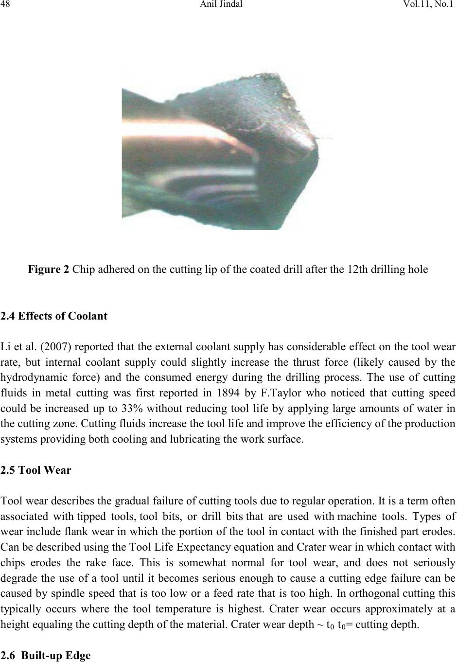 48 Anil Jindal Vol.11, No.1 Figure 2 Chip adhered on the cutting lip of the coated drill after the 12th drilling hole 2.4 Effects of Coolant Li et al. (2007) reported that the external coolant supply has considerable effect on the tool wear rate, but internal coolant supply could slightly increase the thrust force (likely caused by the hydrodynamic force) and the consumed energy during the drilling process. The use of cutting fluids in metal cutting was first reported in 1894 by F.Taylor who noticed that cutting speed could be increased up to 33% without reducing tool life by applying large amounts of water in the cutting zone. Cutting fluids increase the tool life and improve the efficiency of the production systems providing both cooling and lubricating the work surface. 2.5 Tool Wear Tool wear des cribes the gradual failure of cutting tools due to regular operation. It is a term often associated with tipped tools, tool bits, or drill bits that are used with machine tools. Types of wear inclu de flank w ear in which the portion of the tool in contact with the finished part erodes. Can be described using the Tool Life Expectancy equation and Crater wear in which contact with chips erodes the rake face. This is somewhat normal for tool wear, and does not seriously degrade the use of a tool until it becomes serious enough to cause a cutting edge failure can be caused by spindle speed that is too low or a feed rate that is too high. In orthogonal cutting this typically occurs where the tool temperature is highest. Crater wear occurs approximately at a height equaling the cutting depth of the material. Crater wear depth ~ t0 t0= cutting depth. 2.6 Built-up Edge 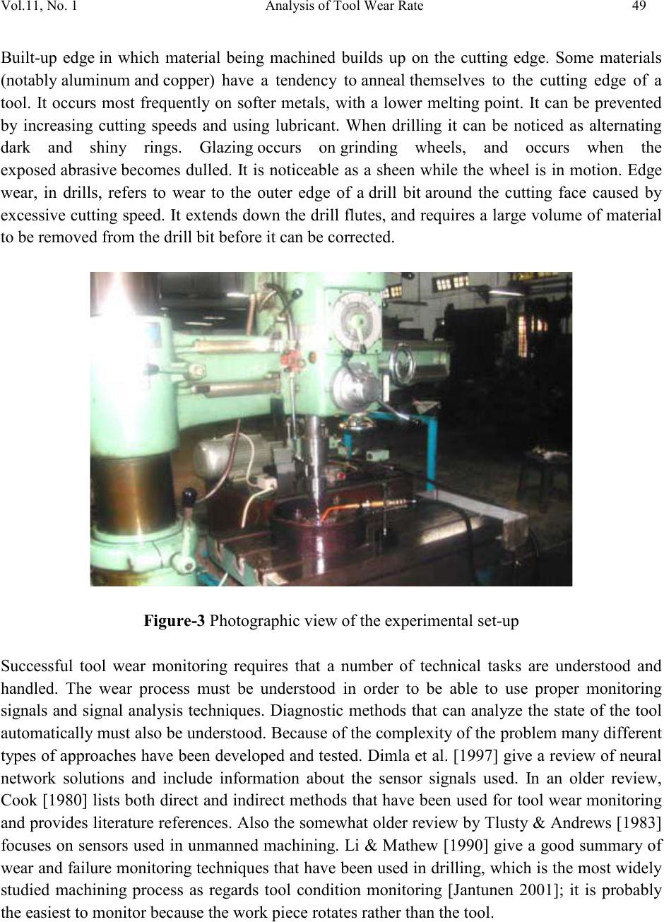 Vol.11, No. 1 Analysis of Tool Wear Rate 49 Built-up edge in which material being machined builds up on the cutting edge. Some materials (notably aluminum and copper) have a tendency to anneal themselves to the cutting edge of a tool. It occurs most frequently on softer metals, with a lower melting point. It can be prevented by increasing cutting speeds and using lubricant. When drilling it can be noticed as alternating dark and shiny rings. Glazing occurs on grinding wheels, and occurs when the exposed abrasive becomes dulled. It is noticeable as a sheen while the wheel is in motion. Edge wear, in drills, refers to wear to the outer edge of a drill bit around the cutting face caused by excess ive cutting speed. It extends down the drill flutes, and requires a lar ge volume of material to be removed from the drill bit before it can be corrected. Figure-3 Photographic view of the experimental set-up Successful tool wear monitoring requires that a number of technical tasks are understood and handled. The wear process must be understood in order to be able to use proper monitoring signals and signal analysis techniques. Diagnostic methods that can analyze the state of the tool automatically must also be understood. Because of the complex it y of the problem man y different types of approaches have been developed and tested. Dimla et al. [1997] give a review of neural network solutions and include information about the sensor signals used. In an older review, Cook [ 1980] lists both direct and indirect methods t hat have been used for tool wear monitoring and provides literature references. Also the somewhat older review b y Tlusty & Andrews [1983] focuses on sensors used in unmanned machining. Li & Mathew [1990] give a good summary of wear and failure monitoring techniques that have been used in drilling, wh ich is the most widely studied machining process as regards tool condition monitoring [Jantunen 2001]; it is probably the easiest to monitor because the work piece rotates rather than the tool.  50 Anil Jindal Vol.11, No.1 3. EXPERIMENTAL INVESTIGATION Machining ferrous metals by high speed steel (HSS) is a major activity in the machining industries. Machining of steels involves more heat generation for their ductility and production of continuous chips having more intimate and wide chip-tool contact. Again, the cutting temperature increases further with the increase in strength and hardness of the steels for more specific energy requirement. Keeping these f acts in view th e commonly used steel like mild steel has been undertaken for the present investigations. Considering common interest and time constraint, only HSS have been used for the present investigation. Wide scope will remain for further study on high-pressure coolant (HPC) effect in drilling steels by HSS and exotic materials by high performance drill bit. Figure-4 Nozzle injected HPC (High Pressure Coolant) The drilling tests have been carried out by drilling of mild steel on a drill machine by HSS drill under dry and high pressure coolant conditions. The positioning of the nozzle tip with respect to the HSS drill has been settled after a number of trials. The photographic view of the experimental set-up is shown in Figure-3. The diameter and roundness deviation of the holes were measured by a digital slide calipers. After drilling operation the drill bit was examined under scanning electronic microscope (SEM). The cooling capacit y of the cutting oil at different pressure and flow rate used in this experiment is important. They were found out using an electric furnace. The maximum temperature measured in the middle of the work piece was 400°C, obtained after keeping it inside the furnace for a period of 8 minutes. After heating, the work pieces were submitted to cooling condition similar to the experiments, i.e. high pressure coolant condition at different pressure. The temperature was measured by a K-t ype thermocouple for eight minutes. This thermo-sensor was connected to the work piece through a hole that 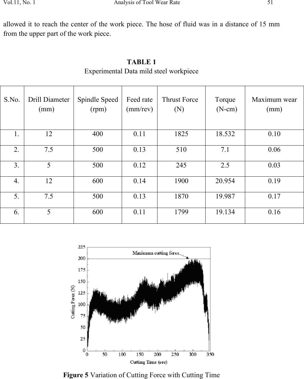 Vol.11, No. 1 Analysis of Tool Wear Rate 51 allowed it to reach the center of the work piece. The hose of fluid was in a distance of 15 mm from the upper part of the work piece. TABLE 1 Experimental Data mild steel workpiece S.No. Drill Diameter (mm) Spindle Speed (rpm) Feed rate (mm/rev) Thrust Force (N) Torque (N-cm) Maximum wear (mm) Figure 5 Variation of Cutting Force with Cutting Time  52 Anil Jindal Vol.11, No.1 The Taylor Equation for Tool Life Expectancy provides a good approximation. VcTn = C A more general form of the equation is Vc Tn × Dx Fy = C where, Vc=cutting speed, T=tool life, D=depth of cut, F=feed rate, x and y are determined experimentally, n and C are constants found by experimentation or published data; they are properties of tool material, workpiece and feed rate. 4. RESULTS AND DISCUSSIONS Chip shape is the most important factor for the smoothness of a drilling process. The drilling process will be smooth if chips are well broken. However, most ductile materials do not break during drilling, and instead, form continuous chips. Based on the chip forming mechanisms, continuous chips can be categorized to spiral chips and string chips. When chips are initially generat ed, b ecaus e the inner cut ting edge m oves s igni ficantly slow er t han t he ou ter cu ttin g ed ge, the inner chip is inherently shorter than the outer chip. This difference in length within the chip forces it flow to the drill center instead of perpendicular to the cutting edge. Furthermore, the center part of the drill flute forces the chip to curl and form a spiral shape. However, when spiral chips move in the drill flute, in order to maintain its spiral shape, they have to constantly rotate on their own axis.This rotational motion causes the spiral chips to have difficulty maintaining their shape as the hole gets deeper. If chips cannot keep up with the rotational motion, they will either break or be forced to move along the flute without spinning, and form string chips. High- pressure coolant (HPC) played very effective role for cooling and provided lubrication between drill bit and chip interface. Figure-6 SEM views of chips produced while drilling steel by HSS drill bit under High pressure coolant condition.  Vol.11, No. 1 Analysis of Tool Wear Rate 53 Figure-6 shows the condition of chips during drilling steel by HSS drill bit under high-pressure coolant (HPC) condition. The shape of the chip produced under dry conditions was spiral but under high-pressure coolant condition became string. The color of the chips became lighter i.e. metallic from burnt blue due to reduction in drilling temperature by high-pressure coolant condition. Before the analysis of the quality parameters of the holes, it is important to note that neither diameter nor any other quality parameter of the hole was influenced by tool wear. In other words, these parameters presented no tendency as feed length increased. The HPC presented a better quality. At high temperature zones crater wear occurs. The highest temperature of the tool can exceed 700 °C and occurs at the rake face whereas the lowest temperature can be 500 °C or lower depending on the tool. Energy comes in the form of heat from tool friction. It is a reasonable assumption that 80% of energy from cutting is carried away in the chip. If not for this the work piece and the tool would be much hotter than what is experienced. The tool and the work piece each carry approximately 10% of the energy. The percent of energy carried away in the chip increases as the speed of the cutting operation increases. This somewhat offsets the tool wear from increased cutting speeds. In fact, if not for the energy taken away in the chip increasing as cutting speed is increased; the tool would wear more quickly than is found. 5. CONCLUSIO N a.) The formation of chip under HPC condition is more favorable in compare to dry condition because of high lubricant capacity. b.) Roundness deviation was smaller at both the entrance and end of the holes under HPC condition in compare to dry condition. When high depth of cut used, the drilling with dr y condition was not possible because of poor cooling and lubrication action. c.) Taper values and their dispersion were smaller under high-pressure coolant condition. Moreover, in both conditions the average taper values were positive i.e., the diameters in the entrance of the holes were bigger than at the end. d.) The beneficial effects of HPC may be attributed to effective lubrication action, which prevents the chip sticking on the tool and makes the cut feasible. REFERENCES [1] Ezugwu E. O. and Lai C. J. 1995. Failure modes and wear mechanisms of M35 high speed steel drills when machining Inconel 901. Journal of Materials Processing Tech. Vol. 49: 295-312.  54 Anil Jindal Vol.11, No.1 [2] Kitagawa T., Kubo A. and Maekawa K. 1997. Temperature and wear of cutting tools in high speed machining of Inconel 718 and Ti-6V-2Sn. Wear. Vol. 202: 142-148. [3] Eyup Bag˘ci and Babur Ozcelik. 2006. Investigation of the effect of drilling conditions on the twist drill temperature during step-by-step and continuous dry drilling. Materials and Design. Vol. 27: 446-454. [4] Matthew Bono and Jun Ni. 2006. International Journal of Machine Tools and Manufacture. Vol. 46: 901-907. [5] Panda S.S., Singh A.K , Chakraborty D. and Pal S.K. 2006. Drill wear monitoring using back propagation neural network. Journal of Materials Processing Technology. Vol. 172: 283-290. [6] Sanjay C., Neemab M.L and Chin C.W. 2005. Modeling of tool wear in drill ing by statistical analysis and artificial neural network. Journal of Materials Processing Technology. Vol. 170: 494-500. [7] Ackroyd B., Compton W.D. and Chandrasekhar S. 1998. Reducing the need for cutting fluids in drilling by means of modulation-assisted drilling. Proceedings of the International Mechanical Engineering Congress and Exposition. Vol. 8: 405–411. [8] Litvinov L.P. 1990. Vibration-assisted drilling of deep holes. Soviet Engineering Research. Vol. 10(5): 5-8. [9] Sahu S.K., DeVor R.E., Kapoor S.G. and Ozdoganlar O.B. 2003. Effect of groove-t ype chip breakers on twist drill performance. International Journal of Machine Tools and Manufacture. Vol. 43: 617-627. [10] Jeff A. Degenhardt, Richard E. DeVor and Shiv G. Kapoors. 2005. Generalized groove-type chip breaker effects on drilling for different drill diameters and flute shapes. International Journal of Machine Tools and Manufacture. Vol. 45: 1588-1597. [11] Davies M. A., Chou Y. and Evans C. J. 1996. On chip morphology, tool wear and cutting mechanics hardened steels. Annals of CIRP. Vol. 45(1): 77-82.
|