Paper Menu >>
Journal Menu >>
 Journal of Minerals & Materials Characterization & Engineering, Vol. 10, No.11, pp.1041-1049, 2011 jmmce.org Printed in the USA. All rights reserved 1041 Characterization of Plasma Sprayed Hydroxyapatite Coatings on AISI 316L SS and Titanium Substrate and their Corrosion Behavior in Simulated Body Fluid Manoj Mittal a *, S. K. Nath a , Satya Prakash a a Metallurgical and Materials Engineering Department, Indian Institute of Technology Roorkee, Civil lines, Roorkee-247667, India *Corresponding author: manojmittal74@yahoo.com ABSTRACT In order to increase the bone bioactivity of metallic implants, hydroxyapatite (HA: Ca 10 (PO 4 ) 2 (OH) 6 ) is often coated on their surface so that real bond with surrounding bone tissue can be formed. In present study, HA coatings were deposited on AISI 316L SS and titanium using shrouded plasma spray process. The coated specimens were subjected to X-ray diffraction (XRD) analysis, field emission scanning electron microscopy (FE-SEM/EDAX). The polarization studies in simulated body fluid (SBF) were conducted to evaluate the corrosion resistance of bare and coated specimens. It was found that the hydroxyapatite coating provided excellent corrosion resistance. The resistance to corrosion was found independent on substrates Keywords: Corrosion, Polarization, Hydroxyapatite. 1. INTRODUCTION Metallic materials such as AISI 316L SS, Ti and its alloys and Co-Cr alloys are commonly employed as orthopedic implants because of their high strength (compared to polymers) and high toughness (compared to ceramic materials) [1]. However, metallic materials are susceptible to corrosive attack by body fluid, with subsequent release of metallic ions, which causes adverse effects to surrounding tissues [2]. Moreover, metallic surfaces may be bioinert up to some extent but not adequately bioactive and surface treatment is usually required to make them bioactive and biocompatible. Hydroxyapatite can bond to living bony tissues and it is being widely used in  1042 Manoj Mittal, S. K. Nath, Satya Prakash Vol.10, No.11 clinical applications. Plasma spraying is most popular method due to its feasibility and low operational cost. Plasma sprayed HA coatings bear good mechanical properties [3]. The corrosion resistance of HA coatings on various metallic substrates in different physiological solutions has been investigated by many researchers [4-8]. Kwok et al. reported that HA coated Ti-6Al-4V possessed higher corrosion resistance compared to uncoated Ti-6Al-4V substrate in Hank’s physiological solution due to lower corrosion current density and noble shift of open- circuit potential [4]. Corrosion resistance of Ni-Ti alloy in simulated body fluid (SBF) was improved by almost 60 times by electrodeposition of HA-zirconia composite coating [5]. Bai et al. deposited CNT- HA coatings on titanium substrate and found better protection efficiency and good biocompatibility in SBF [6]. Gopi and co-workers deposited HA coatings on borate passivated 316L SS and studied corrosion behavior of coatings in Ringer’s solution. They reported polarization potential values of HA coated 316L SS to be nobler than uncoated SS specimens [7]. Hydroxyapatite coated magnesium metal specimen treated with 50 mol/m 3 Ca- EDTA/ 50 mol/m 3 KH 2 PO 4 solution for 8, 16 and 24h subsequently tested for corrosion resistance in 3.5 wt% NaCl solution by Hiromoto and Yamamoto. They reported that HA coated magnesium specimens were 1000 times lesser anodic current density compared to bare magnesium [8]. In present study, hydroxyapatite was deposited on AISI 316L SS and pure titanium using shrouded plasma spray process. The corrosion behavior of the bare and coated specimens was carried out in simulated body fluid. The experiments were conducted for open circuit potential (OCP) and potentiodynamic polarization. The HA coatings offered better corrosion resistance compared to AISI 316L SS and titanium. 2. EXPERIMENTAL PROCEDURE 2.1 Development of Coatings 2.1.1 Substrate material and coating formulation The AISI 316L stainless steel and pure titanium, being bio-inert, were selected as substrate materials in rolled sheet form. Specimens with approximate dimensions 20 mm x 10 mm x 5 mm were cut from metallic sheet and polished with SiC paper down to 220 grit and subsequently grit blasted with alumina powder (Grit 45). The surface was air blasted to remove residual grit. The specimens were cleaned ultrasonically for 20 min in acetone and alcohol prior to deposition of coating by shrouded plasma spraying process. The HA powder having 100% crystallinity with average particle size of 45 µm, a blend of finer and coarse particles (Captal 60 – 1’) was commercially obtained from Plasma Biotal Limited, UK. The weight percentage of heavy metals was less than 0.003% as certified by Exova (UK) Limited. The specimens were coated up to a coating thickness of 150 – 170 µm using a 40 kW Miller thermal plasma spray apparatus available at Anod Plasma Limited, Kanpur, India. Argon was used as powder carrying and  Vol.10, No.11 Characterization of Plasma Sprayed Hydroxyapatite Coatings 1043 shielding gas. All process parameters were kept constant and spray distance was in a narrow range of 90 – 110 mm throughout the coating process. The process conditions were as reported in Table 1. Table 1. Plasma spraying parameters employed for coatings Arc current (A) 750 Arc voltage (V) 40 Powder flow rate (rev/min) 5.5 Spraying distance (mm) 90 - 110 Plasma arc gas (Argon) (psi) 60 Carrier gas (Argon) (psi) 40 Nozzle internal diameter (mm) 8 Coating thickness (µm) 150 – 200 2.1.2. Characterization of the coatings XRD analysis was carried out on powder and as coated specimens using a Bruker AXS D-8 Advanced diffractometer (Germany) with Cu Kα radiation with scanning speed of 1º/min in a scan range of 10 – 60º (2θ) at 40 kW and 100mA. A Quanta 200 F field emission scanning electron microscope fitted with EDAX Genesis software attachment (Czech Republic) was used for SEM/EDAX analysis. The porosity of the coatings along the polished cross-section and on as sprayed coatings was measured with an image analyzer using Dewinter Material Plus 1.01 software based on ASTM B276. A PME3 inverted metallurgical microscope (Olympus, Japan) was used to obtain the images. The average of ten randomly selected points is reported. The surface roughness (Ra) of as-sprayed specimens was measured with non-contact optical profilometer (Wyco NT1100, Veecco Instruments Inc., USA) with software Vision-32. Twenty points, five in each orthogonal direction were selected to measure surface roughness. To identify the cross-section details, the samples were cut in cross-section, mounted and subjected to mirror polishing using 1µm alumina powder suspension in water. The specimens were cleaned ultrasonically and subsequently gold sputter coated using Leica Microsystems cool sputter coater (Model: EM SCD 005, USA). The coating thickness was measured by taking back scattered electron image (BSEI) with FE-SEM using a solid state detector (SSD). 2.2 Electrochemical Experimentation 2.2.1 Simulated body fluid Simulate body fluid used for electrochemical experiments was prepared in accordance with reference 9 [9]. The details of chemical reagents used are described in Table 2.  1044 Manoj Mittal, S. K. Nath, Satya Prakash Vol.10, No.11 Table 2 Composition of chemical reagents for preparation of one litre SBF. NaCl 8.035g NaHCO 3 0.355g KCl 0.225g K 2 HPO 4 ·3H 2 O 0.231g MgCl 2 · 6H 2 O 0.311g 1.0 M HCl 39ml CaCl 2 0.292g Na 2 SO 4 0.072g Tris buffer 6.118g To avoid precipitation of apatite smooth plastic containers (without any scratch) were used. These were soaked in dilute NaCl solution for 12h, washed with distilled water and rinsed with double distilled water before using. The reagents were weighed using digital electronic balance with accuracy of 10 -7 kg. Before using simulated body fluid for experiments, it was kept at 25ºC for 24h to check any precipitation. 2.2.2 Polarization experiments The corrosion behavior of substrate materials and coatings was evaluated in simulated body fluid by open circuit potential and potentiodyanic tests at room temperature. The polarization tests were conducted using Priston Applied Research Advanced Electrochemical System (Model: PARSTAT 2273) equipped with Power Suit software. Two highly pure graphite rods were used as counter electrodes and saturated calomel electrode (SCE) was reference electrode in the electrochemical cell. To make exposed area of specimen 1 cm 2 , the excess area was first covered with plastic tape and then painted with non toxic paint. The specimens were ultrasonically cleaned in double distilled water for 15 min prior to immersing in cell. The specimens were allowed to get stabilized at OCP for 30 min. The linear polarization tests were conducted in range of ±20 mV with respect to corrosion potential (E corr ), potentiodynamic polarization tests were carried out in range -250 mV w.r.t. OCP and 1.6V w.r.t. SCE with a scan rate of 0.25 mV/s. 3. RESULTS AND DISCUSSION 3.1 Characterization of Coatings The SEM image of the as-coated specimen (Fig. 1) shows some unmelted HA particles on the surface of completely molten HA splats with very fine cracks within the splats. The overall 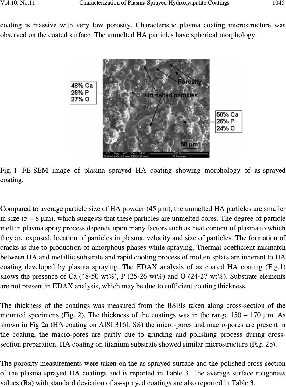 Vol.10, No.11 Characterization of Plasma Sprayed Hydroxyapatite Coatings 1045 coating is massive with very low porosity. Characteristic plasma coating microstructure was observed on the coated surface. The unmelted HA particles have spherical morphology. Fig. 1 FE-SEM image of plasma sprayed HA coating showing morphology of as-sprayed coating. Compared to average particle size of HA powder (45 µm), the unmelted HA particles are smaller in size (5 – 8 µm), which suggests that these particles are unmelted cores. The degree of particle melt in plasma spray process depends upon many factors such as heat content of plasma to which they are exposed, location of particles in plasma, velocity and size of particles. The formation of cracks is due to production of amorphous phases while spraying. Thermal coefficient mismatch between HA and metallic substrate and rapid cooling process of molten splats are inherent to HA coating developed by plasma spraying. The EDAX analysis of as coated HA coating (Fig.1) shows the presence of Ca (48-50 wt%), P (25-26 wt%) and O (24-27 wt%). Substrate elements are not present in EDAX analysis, which may be due to sufficient coating thickness. The thickness of the coatings was measured from the BSEIs taken along cross-section of the mounted specimens (Fig. 2). The thickness of the coatings was in the range 150 – 170 µm. As shown in Fig 2a (HA coating on AISI 316L SS) the micro-pores and macro-pores are present in the coating, the macro-pores are partly due to grinding and polishing process during cross- section preparation. HA coating on titanium substrate showed similar microstructure (Fig. 2b). The porosity measurements were taken on the as sprayed surface and the polished cross-section of the plasma sprayed HA coatings and is reported in Table 3. The average surface roughness values (Ra) with standard deviation of as-sprayed coatings are also reported in Table 3. 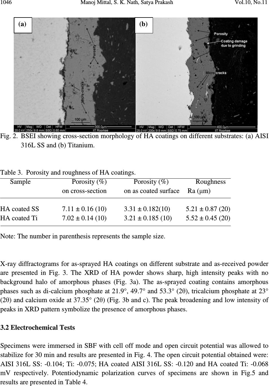 1046 Manoj Mittal, S. K. Nath, Satya Prakash Vol.10, No.11 Fig. 2. BSEI showing cross-section morphology of HA coatings on different substrates: (a) AISI 316L SS and (b) Titanium. Table 3. Porosity and roughness of HA coatings. Sample Porosity (%) Porosity (%) Roughness on cross-section on as coated surface Ra (µm) HA coated SS 7.11 ± 0.16 (10) 3.31 ± 0.182(10) 5.21 ± 0.87 (20) HA coated Ti 7.02 ± 0.14 (10) 3.21 ± 0.185 (10) 5.52 ± 0.45 (20) Note: The number in parenthesis represents the sample size. X-ray diffractograms for as-sprayed HA coatings on different substrate and as-received powder are presented in Fig. 3. The XRD of HA powder shows sharp, high intensity peaks with no background halo of amorphous phases (Fig. 3a). The as-sprayed coating contains amorphous phases such as di-calcium phosphate at 21.9°, 49.7° and 53.3° (2θ), tricalcium phosphate at 23° (2θ) and calcium oxide at 37.35° (2θ) (Fig. 3b and c). The peak broadening and low intensity of peaks in XRD pattern symbolize the presence of amorphous phases. 3.2 Electrochemical Tests Specimens were immersed in SBF with cell off mode and open circuit potential was allowed to stabilize for 30 min and results are presented in Fig. 4. The open circuit potential obtained were: AISI 316L SS: -0.104; Ti: -0.075; HA coated AISI 316L SS: -0.120 and HA coated Ti: -0.068 mV respectively. Potentiodynamic polarization curves of specimens are shown in Fig.5 and results are presented in Table 4. (a) (b) 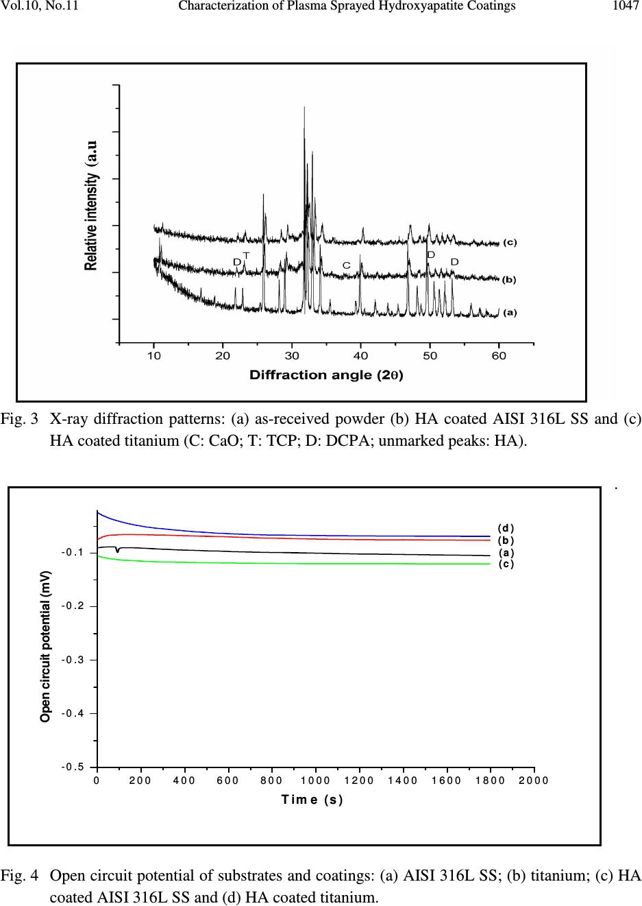 Vol.10, No.11 Characterization of Plasma Sprayed Hydroxyapatite Coatings 1047 Fig. 3 X-ray diffraction patterns: (a) as-received powder (b) HA coated AISI 316L SS and (c) HA coated titanium (C: CaO; T: TCP; D: DCPA; unmarked peaks: HA). . Fig. 4 Open circuit potential of substrates and coatings: (a) AISI 316L SS; (b) titanium; (c) HA coated AISI 316L SS and (d) HA coated titanium. (a.u .) 02 0 04 0 06 008 0 01 0 0 01 2 0 01 4 0 01 6 0 01 8 0 02 0 0 0 - 0. 5 - 0. 4 - 0. 3 - 0. 2 - 0. 1 (d ) (c ) (b ) (a ) Open circuit potential (mV) Tim e (s) 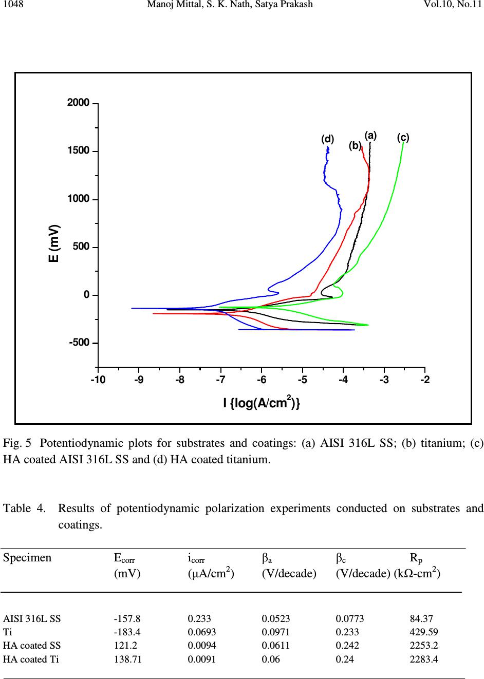 1048 Manoj Mittal, S. K. Nath, Satya Prakash Vol.10, No.11 Fig. 5 Potentiodynamic plots for substrates and coatings: (a) AISI 316L SS; (b) titanium; (c) HA coated AISI 316L SS and (d) HA coated titanium. Table 4. Results of potentiodynamic polarization experiments conducted on substrates and coatings. Specimen E corr i corr β a β c R p (mV) (µA/cm 2 ) (V/decade) (V/decade) (kΩ-cm 2 ) AISI 316L SS -157.8 0.233 0.0523 0.0773 84.37 Ti -183.4 0.0693 0.0971 0.233 429.59 HA coated SS 121.2 0.0094 0.0611 0.242 2253.2 HA coated Ti 138.71 0.0091 0.06 0.24 2283.4 -10-9 -8 -7 -6 -5 -4 -3 -2 -500 0 500 1000 1500 2000 (d) (c) (b) (a) E (mV) I {log(A/cm 2 )} 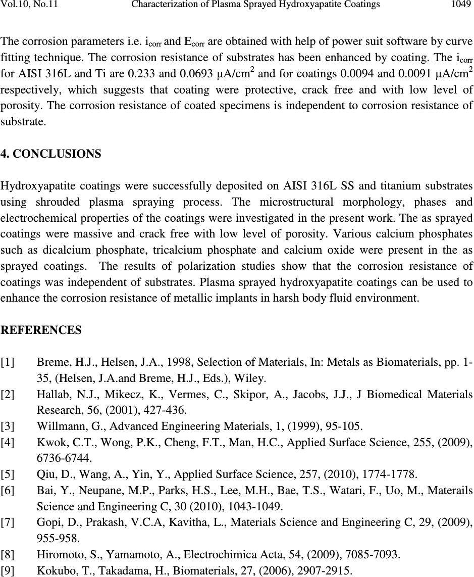 Vol.10, No.11 Characterization of Plasma Sprayed Hydroxyapatite Coatings 1049 The corrosion parameters i.e. i corr and E corr are obtained with help of power suit software by curve fitting technique. The corrosion resistance of substrates has been enhanced by coating. The i corr for AISI 316L and Ti are 0.233 and 0.0693 µA/cm 2 and for coatings 0.0094 and 0.0091 µA/cm 2 respectively, which suggests that coating were protective, crack free and with low level of porosity. The corrosion resistance of coated specimens is independent to corrosion resistance of substrate. 4. CONCLUSIONS Hydroxyapatite coatings were successfully deposited on AISI 316L SS and titanium substrates using shrouded plasma spraying process. The microstructural morphology, phases and electrochemical properties of the coatings were investigated in the present work. The as sprayed coatings were massive and crack free with low level of porosity. Various calcium phosphates such as dicalcium phosphate, tricalcium phosphate and calcium oxide were present in the as sprayed coatings. The results of polarization studies show that the corrosion resistance of coatings was independent of substrates. Plasma sprayed hydroxyapatite coatings can be used to enhance the corrosion resistance of metallic implants in harsh body fluid environment. REFERENCES [1] Breme, H.J., Helsen, J.A., 1998, Selection of Materials, In: Metals as Biomaterials, pp. 1- 35, (Helsen, J.A.and Breme, H.J., Eds.), Wiley. [2] Hallab, N.J., Mikecz, K., Vermes, C., Skipor, A., Jacobs, J.J., J Biomedical Materials Research, 56, (2001), 427-436. [3] Willmann, G., Advanced Engineering Materials, 1, (1999), 95-105. [4] Kwok, C.T., Wong, P.K., Cheng, F.T., Man, H.C., Applied Surface Science, 255, (2009), 6736-6744. [5] Qiu, D., Wang, A., Yin, Y., Applied Surface Science, 257, (2010), 1774-1778. [6] Bai, Y., Neupane, M.P., Parks, H.S., Lee, M.H., Bae, T.S., Watari, F., Uo, M., Materails Science and Engineering C, 30 (2010), 1043-1049. [7] Gopi, D., Prakash, V.C.A, Kavitha, L., Materials Science and Engineering C, 29, (2009), 955-958. [8] Hiromoto, S., Yamamoto, A., Electrochimica Acta, 54, (2009), 7085-7093. [9] Kokubo, T., Takadama, H., Biomaterials, 27, (2006), 2907-2915. |