Paper Menu >>
Journal Menu >>
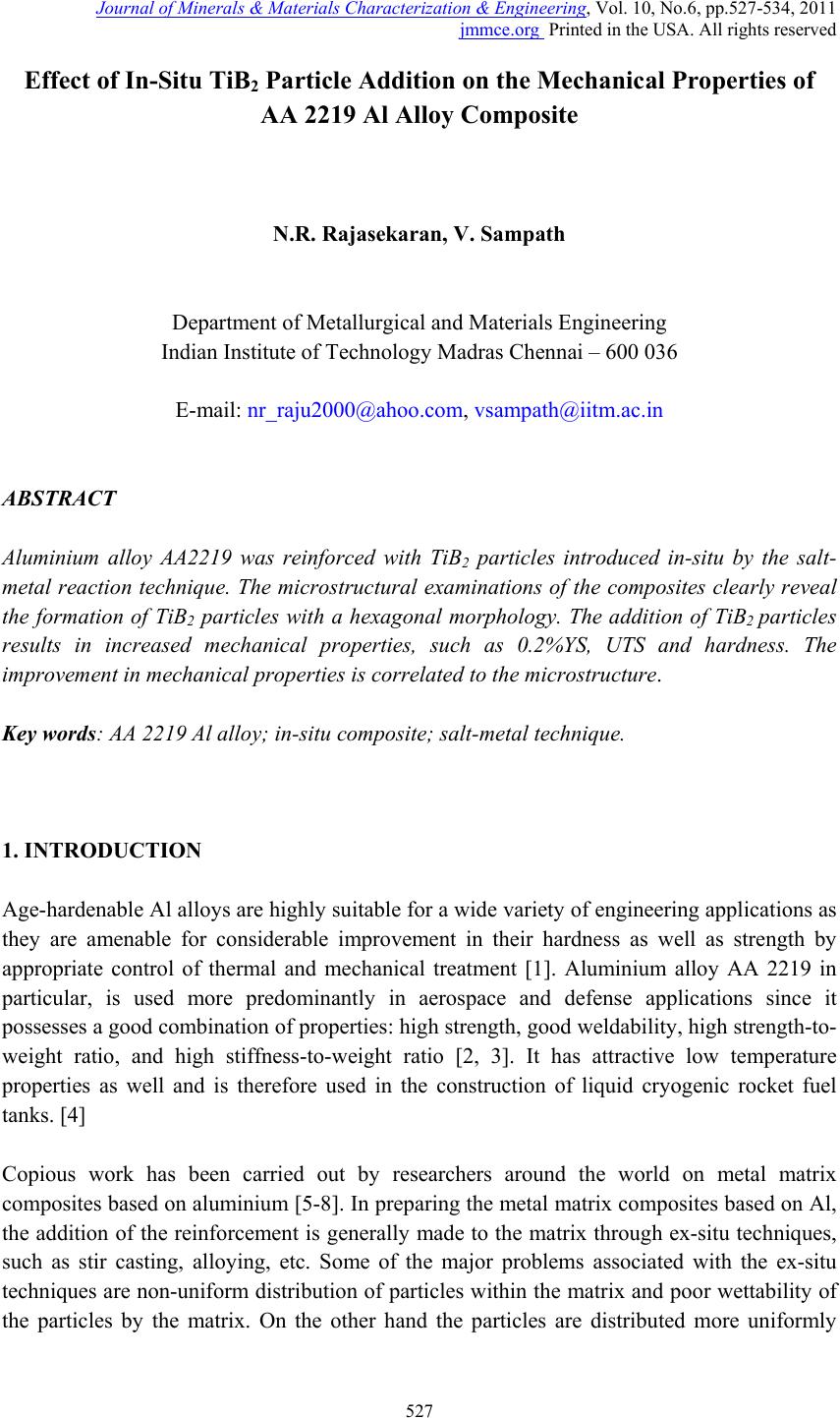 Journal of Minera ls & Materials Ch ar ac teri zatio n & Engineeri ng, Vol. 10, No.6, pp.527-534, 2011 jmmce.org Printed in the USA. All rights reserved 527 Effect of In-Situ TiB2 Particle Addition on the Mechanical Properties of AA 2219 Al Alloy Composite N.R. Rajasekaran, V. Sampath Department of Metallurgical and Materials Engineering Indian Institute of Technology Madras Chennai – 600 036 E-mail: nr_raju2000@ahoo.com, vsampath@iitm.ac.in ABSTRACT Aluminium alloy AA2219 was reinforced with TiB2 particles introduced in-situ by the salt- metal reaction technique. The microstructural examinations of the composites clearly reveal the formation of TiB2 particles with a hexagonal morphology. The addition of TiB2 particles results in increased mechanical properties, such as 0.2%YS, UTS and hardness. The improvement in mechanical properties is correlated to the microstructure. Key words: AA 2219 Al alloy; in-situ composite; salt-metal technique. 1. INTRODUCTION Age-hardenable Al alloys are highly suitable for a wide variety of engineering applications as they are amenable for considerable improvement in their hardness as well as strength by appropriate control of thermal and mechanical treatment [1]. Aluminium alloy AA 2219 in particular, is used more predominantly in aerospace and defense applications since it possesses a good combination of properties: high strength, good weldability, high strength-to- weight ratio, and high stiffness-to-weight ratio [2, 3]. It has attractive low temperature properties as well and is therefore used in the construction of liquid cryogenic rocket fuel tanks. [4] Copious work has been carried out by researchers around the world on metal matrix composites based on aluminium [5-8]. In preparing the metal matrix composites based on Al, the addition of the reinforcement is generally made to the matrix through ex-situ techniques, such as stir casting, alloying, etc. Some of the major problems associated with the ex-situ techniques are non-uniform distribution of particles within the matrix and poor wettability of the particles by the matrix. On the other hand the particles are distributed more uniformly 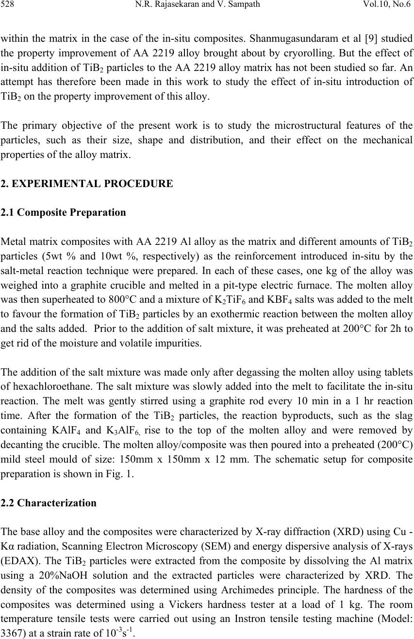 528 N.R. Rajasekaran and V. Sampath Vol.10, No.6 within the matrix in the case of the in-situ composites. Shanmugasundaram et al [9] studied the property improvement of AA 2219 alloy brought about by cryorolling. But the effect of in-situ addition of TiB2 particles to the AA 2219 alloy matrix has not been studied so far. An attempt has therefore been made in this work to study the effect of in-situ introduction of TiB2 on the property improvement of this alloy. The primary objective of the present work is to study the microstructural features of the particles, such as their size, shape and distribution, and their effect on the mechanical properties of the alloy matrix. 2. EXPERIMENTAL PROCEDURE 2.1 Composite Preparation Metal matrix composites with AA 2219 Al alloy as the matrix and different amounts of TiB2 particles (5wt % and 10wt %, respectively) as the reinforcement introduced in-situ by the salt-metal reaction technique were prepared. In each of these cases, one kg of the alloy was weighed into a graphite crucible and melted in a pit-type electric furnace. The molten alloy was then superheated to 800°C and a mixture of K2TiF6 and KBF4 salts was added to the melt to favour the formation of TiB2 particles by an exothermic reaction between the molten alloy and the salts added. Prior to the addition of salt mixture, it was preheated at 200°C for 2h to get rid of the moisture and volatile impurities. The addition of the salt mixture was made only after degassing the molten alloy using tablets of hexachloroethane. The salt mixture was slowly added into the melt to facilitate the in-situ reaction. The melt was gently stirred using a graphite rod every 10 min in a 1 hr reaction time. After the formation of the TiB2 particles, the reaction byproducts, such as the slag containing KAlF4 and K3AlF6, rise to the top of the molten alloy and were removed by decanting the crucible. The molten alloy/composite was then poured into a preheated (200°C) mild steel mould of size: 150mm x 150mm x 12 mm. The schematic setup for composite preparation is shown in Fig. 1. 2.2 Characterization The base alloy and the composites were characterized by X-ray diffraction (XRD) using Cu - Kα radiation, Scanning Electron Microscopy (SEM) and energy dispersive analysis of X-rays (EDAX). The TiB2 particles were extracted from the composite by dissolving the Al matrix using a 20%NaOH solution and the extracted particles were characterized by XRD. The density of the composites was determined using Archimedes principle. The hardness of the composites was determined using a Vickers hardness tester at a load of 1 kg. The room temperature tensile tests were carried out using an Instron tensile testing machine (Model: 3367) at a strain rate of 10-3s-1. 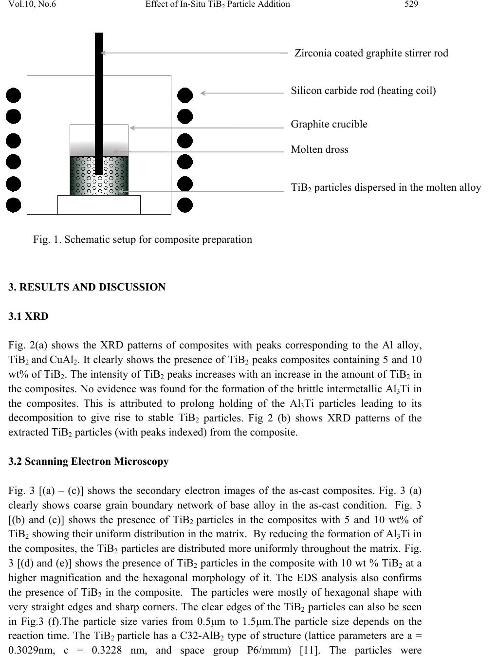 Vol.10, No.6 Effect of In-Situ TiB2 Particle Addition 529 . 3. RESULTS AND DISCUSSION 3.1 XRD Fig. 2(a) shows the XRD patterns of composites with peaks corresponding to the Al alloy, TiB2 and Cu Al2. It clearly shows the presence of TiB2 peaks composites containing 5 and 10 wt% of TiB2. The intensity of TiB2 peaks increases with an increase in the amount of TiB2 in the composites. No evidence was found for the formation of the brittle intermetallic Al3Ti in the composites. This is attributed to prolong holding of the Al3Ti particles leading to its decomposition to give rise to stable TiB2 particles. Fig 2 (b) shows XRD patterns of the extracted TiB2 particles (with peaks indexed) from the composite. 3.2 Scanning Electron Microscopy Fig. 3 [(a) – (c)] shows the secondary electron images of the as-cast composites. Fig. 3 (a) clearly shows coarse grain boundary network of base alloy in the as-cast condition. Fig. 3 [(b) and (c)] shows the presence of TiB2 particles in the composites with 5 and 10 wt% of TiB2 showing their uniform distribution in the matrix. By reducing the formation of Al3Ti in the composites, the TiB2 particles are distributed more uniformly throughout the matrix. Fig. 3 [(d) and (e)] shows the presence of TiB2 particles in the composite with 10 wt % TiB2 at a higher magnification and the hexagonal morphology of it. The EDS analysis also confirms the presence of TiB2 in the composite. The particles were mostly of hexagonal shape with very straight edges and sharp corners. The clear edges of the TiB2 particles can also be seen in Fig.3 (f).The particle size varies from 0.5μm to 1.5µm.The particle size depends on the reaction time. The TiB2 particle has a C32-AlB2 type of structure (lattice parameters are a = 0.3029nm, c = 0.3228 nm, and space group P6/mmm) [11]. The particles were Zirconia coated graphite stirrer rod Silicon carbide rod (heating coil) Graphite crucible Molten dross TiB2 particles dispersed in the molten alloy Fig. 1. Schematic setup for composite preparation  530 N.R. Rajasekaran and V. Sampath Vol.10, No.6 homogeneously distributed around the grain boundaries and also can be seen clearly in Fig. 3(e). Agglomerated particles are conspicuous by their absence. Elemental mapping (Al, Cu, and Ti) was also done to find the distribution of TiB2 particles in the composite. Information relating to the dimensions and morphology of TiB2 can be obtained from Fig. 3(g). Fig. 2(a). XRD pattern for the base alloy and those for the composites with 5 and 10 wt % of TiB2. Fig 2 (b) XRD pattern of extracted TiB2 particles (with peaks indexed) for the composite with 10 wt % of TiB2.  Vol.10, No.6 Effect of In-Situ TiB2 Particle Addition 531 Fig 3(a) Micrograph of as- cast AA 2219 Al alloy Fig.3 (b) Micrograph of AA2219 Al alloy - 5% TiB2 Fig 3 (c) Micrograph of AA2219 Al alloy -10 % TiB2 Fig 3 (d) Micrograph showing the Distribution of TiB2 particles in 5 wt% TiB2 composite Fig 3 (e) Micrograph showing TiB2 particles forming Fig 3 (f) Individual TiB2 particle a network at the grain boundaries in 10 wt % of TiB2 composite  532 N.R. Rajasekaran and V. Sampath Vol.10, No.6 . Fig 3 (g) Dimensions of individual TiB2 particle 3.3 Mechanical Properties Material 0.2%YS (MPa) UTS (MPa) Hardness (VHN) Elongation (%) AA 2219 Al alloy 144 211 63 11.0 AA 2219 Al alloy – 5%TiB2 165 219 87 7.0 AA 2219 Al alloy – 10%TiB2 205 234 96 5.8 The yield strength values were measured by 0.2% offset method. It is clear that the addition of TiB2 particles in-situ to the aluminium alloy matrix increases the mechanical properties of the composite although there is a slight reduction in the ductility. The particle size of the TiB2 in the composite is in the range of 0.5 -1.5 µm and the particles were well dispersed in the matrix. These are desirable factors for the Orowan strengthening mechanism [10]. The hard in-situ TiB2 particles pin down the dislocation line and favour the formation of Orowan loops (dislocation loops) around the particles. The loops reduce the distance between the particles and thus provide more resistance to further dislocation movement in the composite during deformation. This enhances the strength of the composites. In addition, grain boundary strengthening is also expected because the TiB2 can act as a grain refiner in Al alloys. An increase in volume fraction of TiB2 particles reduces the grain size of the cast alloy from 115 μm to ~ 40 μm (10 wt % TiB2 composite). As per the Hall-Petch relationship the yield strength is inversely proportional to the grain size. Hence the yield strength of composite increased due to reduction in grain size. The as-cast alloy shows poor mechanical properties because of its coarse cast structure. The hardness of the in-situ composite is higher than that of the base alloy owing to the reasons put forth earlier. 3.4 Fractography Fig 4 [a and b] show the fractographs of the samples tested in tension. It can be clearly observed that lot of relatively equiaxed dimples and fibrous ligaments are present on the  Vol.10, No.6 Effect of In-Situ TiB2 Particle Addition 533 surface. It reveals the ductile mode of fracture. Inside the dimples TiB2 particles were very well harboured confirming the good bonding/wettability between the matrix and the in-situ TiB2 particles. The dimples were found to be much shallower due to the presence of TiB2 particles and their size was reduced by increasing the fraction of TiB2 particles. This confirms that the particles are well distributed in, and bonded to, the matrix. The fractographs clearly show that the composite failed at the interface between the ductile Al matrix and TiB2 particles and some fibrous ligaments were also observed at the interfaces. This indicates that a small amount of plasticity that the composite undergoes. Since TiB2 particles are anchored at the grain boundaries they will increase the resistance to the crack propagation and therefore it will increase the toughness and strength of composites. Fig.4 (a) and (b) shows fractographs of as-cast 2219 alloy with 5% TiB2 and 10 % TiB2 particles. 4. CONCLUSIONS 1. In-situ AA2219 Al alloy composites containing different weight fractions of particles of TiB2 phase were synthesized successfully by the salt-metal reaction method and the particles were distributed evenly in the matrix of the composites. By prolonged holding at the solutionizing temperature, the formation of the deleterious phase Al3Ti, which drastically affects the mechanical properties, was precluded. 2. The particles of the TiB2 phase show a hexagonal morphology with straight and sharp edges. 3. The mechanical properties of the composites were also evaluated and the increased volume fraction of the TiB2 particles contributed to the increased strength of the composites. REFERENCES 1. J.R. Davis, ASM Speciality Handbook: Aluminium and Aluminium Alloys 1993.  534 N.R. Rajasekaran and V. Sampath Vol.10, No.6 2. N. Kamp et al. 2007,” Influence of grain structure and slip planarity on fatigue crack growth in low alloying artificially aged 2xxx aluminum alloys” Int. J. Fatigue, 29, pp.869-878. 3. K. Surekha, B.S. Murty, K. Prasad Rao , 2008, “ Microstructural characterization and corrosion behavior of multi pass friction stir processed AA 2219 aluminium alloy” Surface Coatings and Technology, 202, pp. 4057-4068. 4. P. Srinivasa Rao, K.G. Sivadasn, P.K. Balasubramanian, 1996, “Structure- Property correlation on AA 2219 aluminium alloy weldments” Bulletin of Material Scien ce 19, pp. 549-557. 5. Tiejun Ma et al, 2003, “Dry sliding wear behaviour of cast SiC-reinforced Al MMCs” Materials Science and Engineering A, 360, pp.116-125. 6. A. Jha, C. Dometakis, 1997, “The dispersion mechanism of TiB2 ceramic phase in molten aluminium and its alloys” Materials & Design 18, pp. 297-301. 7. X. Wang et al 1999, “ Microstructural analysis of Al alloys dispersed with TiB2 particulate for MMC applications “ Journal of Microscopy, 196, pp 137-145. 8. I.G. Watson et al. 2005, “Investigation of the clustering behaviour of titanium diboride particles in aluminium” Composites: Part A, 36, pp 1177-1187. 9. T. Shanmugasundaram, B.S. Murty, V. Subramanya Sarma, 2006, “ Development of ultrafine grained high strength Al-Cu alloy by cryorolling” Scripta Materialia 54, pp.2013-2017 10. L. Iain, Principles of Mechanical Metallurgy, Edward Arnold, Ltd., 1981, pp.155 11. Degang Zhao et al, 2005, “In-situ preparation of Al matrix Composites reinforced by TiB2 Particles and sub micron ZrB2” Journal of Material Science, 40, pp 4365-4368. |