Paper Menu >>
Journal Menu >>
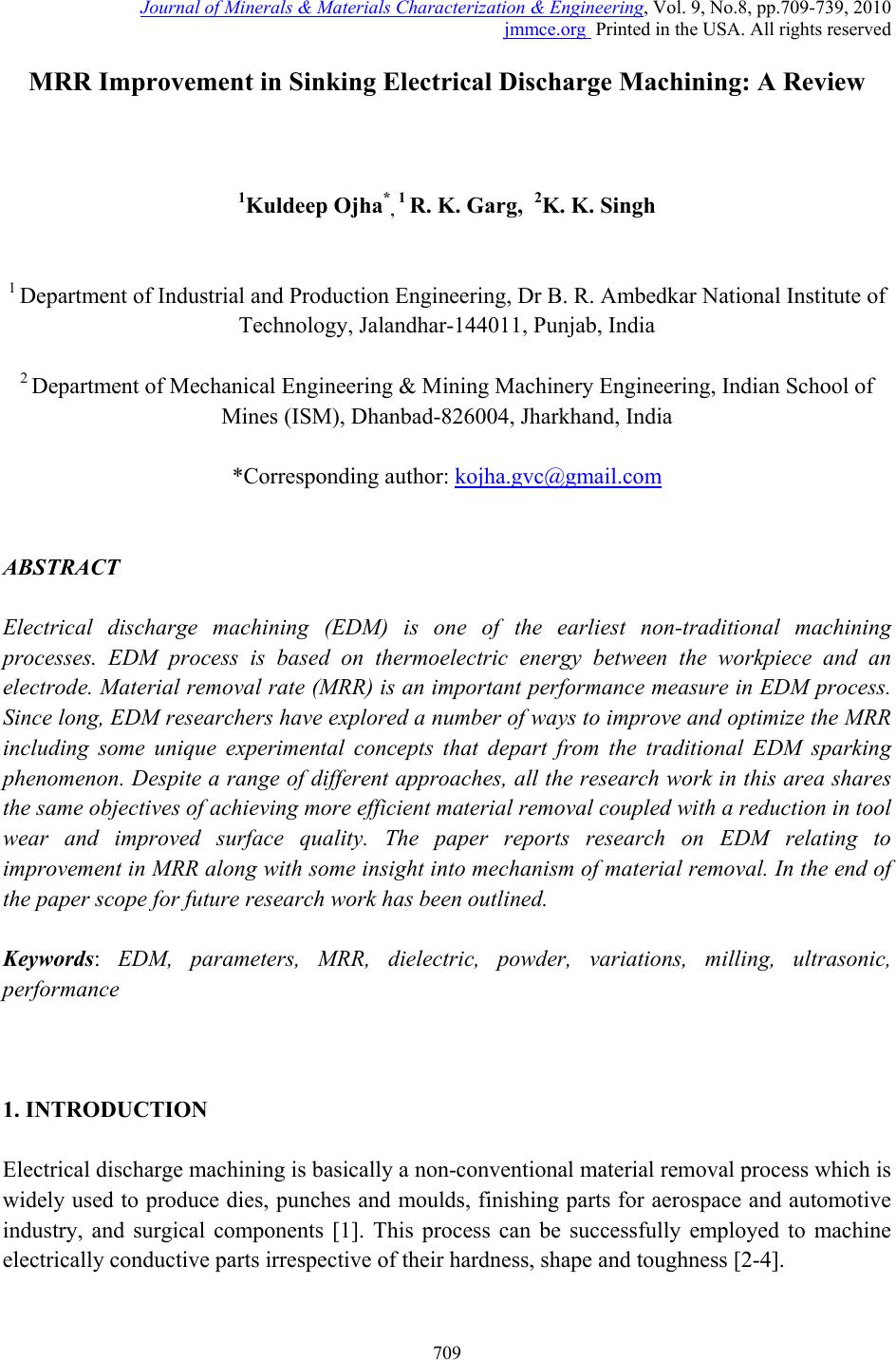 Journal of Minerals & Materials Characterization & Engineering, Vol. 9, No.8, pp.709-739, 2010 jmmce.org Printed in the USA. All rights reserved 709 MRR Improvement in Sinking Electrical Discharge Machining: A Review 1Kuldeep Ojha*, 1 R. K. Garg, 2K. K. Singh 1 Department of Industrial and Production Engineering, Dr B. R. Ambedkar Natio nal Institute of Technology, Jalandhar-144011, Punjab, India 2 Department of Mechanical Engineering & Mining Machinery Engineering, Indian School of Mines (ISM), Dhanbad-826004, Jharkhand, India *Corresponding author: kojha.gvc@gmail.com ABSTRACT Electrical discharge machining (EDM) is one of the earliest non-traditional machining processes. EDM process is based on thermoelectric energy between the workpiece and an electrode. Material removal rate (MRR) is an important performance measure in EDM process. Since long, EDM researchers have explored a number of ways to improve and optimize the MRR including some unique experimental concepts that depart from the traditional EDM sparking phenomenon. Despite a range of different approaches, all the research work in this area shares the same objectives of achieving more efficient material removal coupled with a reduction in tool wear and improved surface quality. The paper reports research on EDM relating to improvement in MRR along with some insight into mechanism of material removal. In the end of the paper scope for future research work has been outlined. Keywords: EDM, parameters, MRR, dielectric, powder, variations, milling, ultrasonic, performance 1. INTRODUCTION Electrical discharge machining is basically a non-conventional material removal process which is widely used to produce dies, punches and moulds, finishing parts for aerospace and automotive industry, and surgical components [1]. This process can be successfully employed to machine electrically conductive part s irrespective of their hardness, shape and toughness [2-4]. 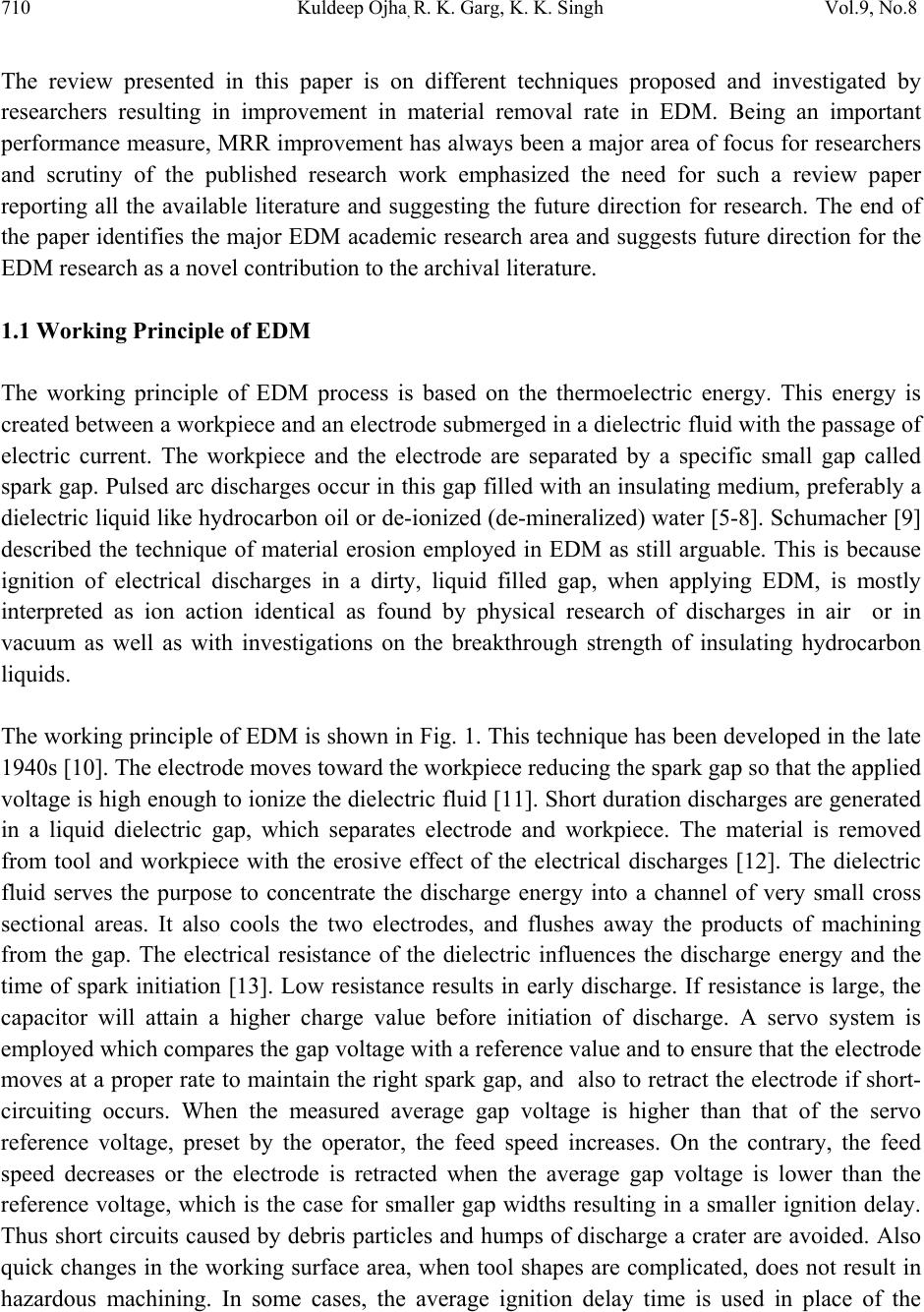 710 K ul deep Ojha, R. K. Garg, K. K. Singh Vol.9, No.8 The review presented in this paper is on different techniques proposed and investigated by researchers resulting in improvement in material removal rate in EDM. Being an important performance measure, MRR improvement has always been a major area of focus for researchers and scrutiny of the published research work emphasized the need for such a review paper reporting all the available literature and suggesting the future direction for research. The end of the paper identifies the major EDM academic research area and suggests future direction for the EDM research as a novel contribution to the archival literature. 1.1 Working Principle of EDM The working principle of EDM process is based on the thermoelectric energy. This energy is created between a workpiece and an electrode submerged in a dielectric fluid with the passage of electric current. The workpiece and the electrode are separated by a specific small gap called spark gap. Pulsed arc discharges occur in this gap filled with an insulating medium, preferably a dielectric liquid like hydrocarbon oil or de-ionized (de-mineralized) water [5-8]. Schumacher [9] described the technique of material erosion employed in EDM as still arguable. This is because ignition of electrical discharges in a dirty, liquid filled gap, when applying EDM, is mostly interpreted as ion action identical as found by physical research of discharges in air or in vacuum as well as with investigations on the breakthrough strength of insulating hydrocarbon liquids. The working principle of EDM is shown in Fig. 1. This technique has been developed in the late 1940s [10]. The electrode moves toward the workpiece reducing the spark gap so that the applied voltage is high enough to ionize the dielectric fluid [11]. Short duration discharges are generated in a liquid dielectric gap, which separates electrode and workpiece. The material is removed from tool and workpiece with the erosive effect of the electrical discharges [12]. The dielectric fluid serves the purpose to concentrate the discharge energy into a channel of very small cross sectional areas. It also cools the two electrodes, and flushes away the products of machining from the gap. The electrical resistance of the dielectric influences the discharge energy and the time of spark initiation [13]. Low resistance results in early discharge. If resistance is large, the capacitor will attain a higher charge value before initiation of discharge. A servo system is employed which compares the gap voltage with a reference value and to ensure that the electrode moves at a proper rate to maintain the right spark gap, and also to retract the electrode if short- circuiting occurs. When the measured average gap voltage is higher than that of the servo reference voltage, preset by the operator, the feed speed increases. On the contrary, the feed speed decreases or the electrode is retracted when the average gap voltage is lower than the reference voltage, which is the case for smaller gap widths resulting in a smaller ignition delay. Thus short circuits caused by debris particles and humps of discharge a crater are avoided. Also quick changes in the working surface area, when tool shapes are complicated, does not result in hazardous machining. In some cases, the average ignition delay time is used in place of the 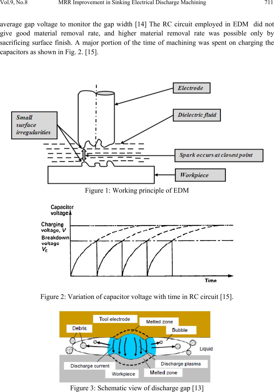 Vol.9, No.8 MRR Improvement in Sinking Electrical Discharge Machining 711 average gap voltage to monitor the gap width [14] The RC circuit employed in EDM did not give good material removal rate, and higher material removal rate was possible only by sacrificing surface finish. A major portion of the time of machining was spent on charging the capacitors as shown in Fig. 2. [15]. Figure 1: Working principle of EDM Figure 2: Variation of capacitor voltage with time in RC circuit [15]. Figure 3: Schematic view of discharge gap [13]  712 K ul deep Ojha, R. K. Garg, K. K. Singh Vol.9, No.8 Fig. 3 shows a systematic view of EDM spark spot [13]. The arc column diameter increases with the passage of time [16-18] and equal to the diameter of the generated discharge crater [16]. In the spark gap electrode materials and dielectric liquid are evaporated, molecules are dissociated, and atoms are ionized, resulting in a rapid expansion of the bubble from dielectric fluid. Since the expansion is restricted by the inertia and viscosity of the dielectric, the pressure inside the bubble becomes extremely high and the boundary between the bubble and liquid expands with the velocity of several tens m/s [19, 20]. It is still believed that the dielectric liquid plays a significant role in material removal because the high pressure and velocity field in the bubble may serve as the dynamics of the material removal in EDM [21, 22] In this process there is no direct contact between the electrode and the workpiece thus eliminating mechanical stresses, chatter and vibration problems during machining [1]. Trends on activities carried out by researchers depend on the interest of the researchers and the availability of the technology. Rajurkar [23] has indicated some future trends activities in EDM: machining advanced materials, mirror surface finish using powder additives, ultrasonic-assisted EDM and control and automati on. 1.2 Process Parameters and Performance Measures The process parameters and performance measures are shown in Fig. 4. The process parameters can be divided into two categories i.e. electrical and non-electrical parameters. Major electrical parameters are discharge voltage, peak current, pulse duration and pulse interval, electrode gap, polarity and pulse wave form. The EDM process is of stochastic thermal nature having complicated discharge mechanism [24]. Therefore, it is difficult to explain all the effect of these parameters on performance measures. However, researchers now rely on process analysis for optimization of parameters to identify the effect of operating variables on achieving the desired machining characteristics. Lin et al. [25] applied grey relational analysis for solving the complicated interrelationships between process parameters and the multiple performance measures. Taguchi approach has also been used by many other researchers to analyze and design the ideal EDM process [26-28]. Main non-electrical parameters are flushing of dielectric, workpiece rotation and electrode rotation. These non electrical parameters play a critical role in optimizing performance measures. Researches on flushing pressure reveal that it affects the surface roughness, tool wear rate, acts as coolant and also plays a vital role in flushing away the debris from the machining gap [29-31]. Workpiece rotary motion improves the circulation of the dielectric fluid in the spark gap and temperature distribution of the workpiece yielding better MRR and SR [32]. Similarly, electrode rotation results in better flushing action and sparking efficiency [33]. Therefore, improvement in MRR and SR has been reported due to effective gap flushing by electrode rotation [34-36]. 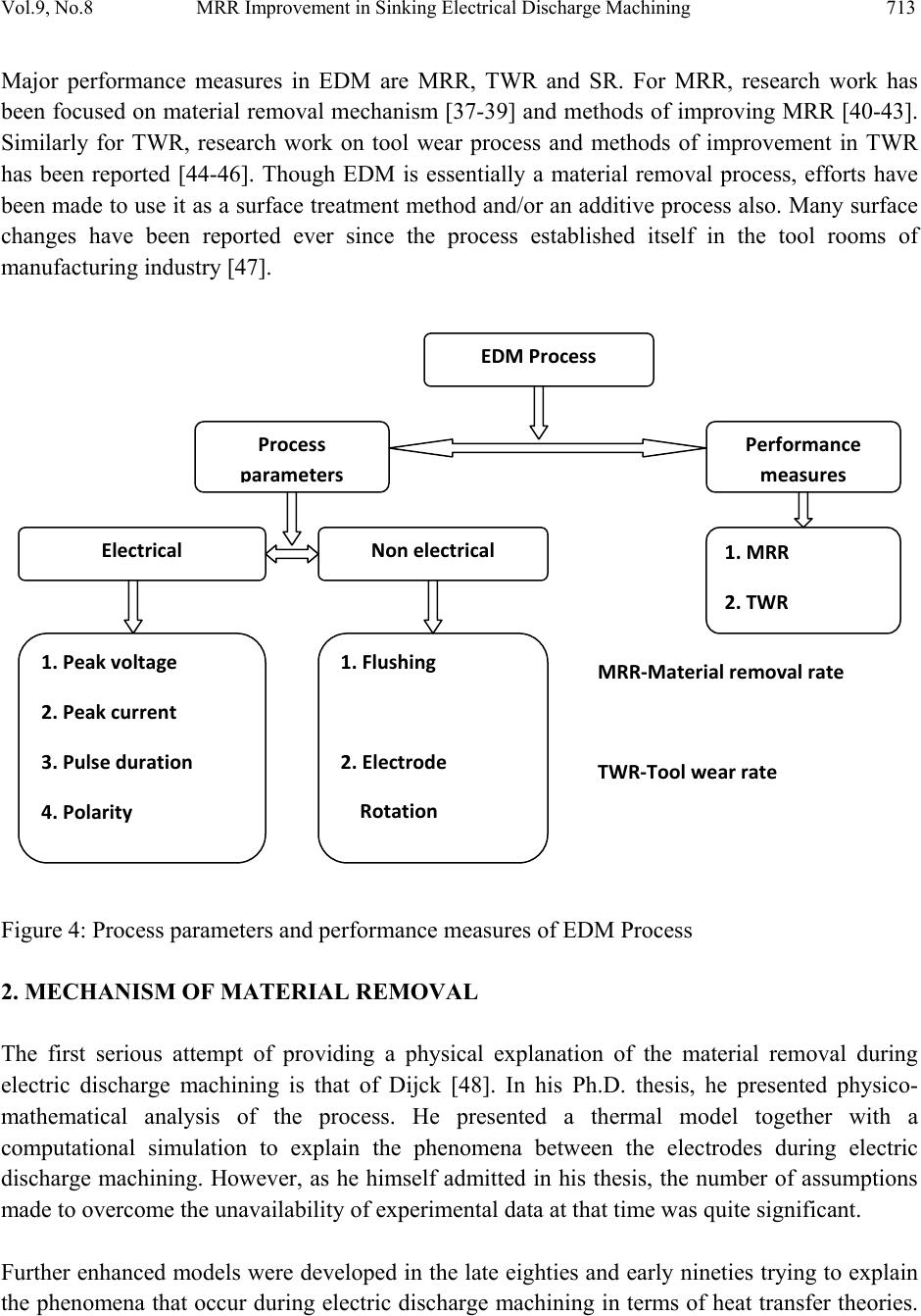 Vol.9, No.8 MRR Improvement in Sinking Electrical Discharge Machining 713 Major performance measures in EDM are MRR, TWR and SR. For MRR, research work has been focused on material removal mechanism [37-39] and methods of improving MRR [40-43]. Similarly for TWR, research work on tool wear process and methods of improvement in TWR has been reported [44-46]. Though EDM is essentially a material removal process, efforts have been made to use it as a surface treatment method and/or an additive process also. Many surface changes have been reported ever since the process established itself in the tool rooms of manufacturing industry [47]. Figure 4: Process parameters and performance measures of EDM Process 2. MECHANISM OF MATERIAL REMOVAL The first serious attempt of providing a physical explanation of the material removal during electric discharge machining is that of Dijck [48]. In his Ph.D. thesis, he presented physico- mathematical analysis of the process. He presented a thermal model together with a computational simulation to explain the phenomena between the electrodes during electric discharge machining. However, as he himself admitted in his thesis, the number of assumptions made to overcome the unavailability of experimental data at that time was quite significant. Further enhanced models were developed in the late eighties and early nineties trying to explain the phenomena that occur during electric discharge machining in terms of heat transfer theories. EDMProcess Process p a r a m e t e r s Performance m easu r es ElectricalNonelectrical 1.Flushing 2.Electrode Rotation 1.MRR 2.TWR MRR‐Materialremovalrate TWR‐Toolwearrate 1.Peakvoltage 2.Peakcurrent 3.Pulseduration 4.Polarity  714 K ul deep Ojha, R. K. Garg, K. K. Singh Vol.9, No.8 Probably the most advanced explanation of the EDM process as a thermal process w as developed during an investigation carried out at Texas A&M University: this stream of research resulted in a series of three research papers. In the first paper, a simple cathode erosion model for the process was presented [49]. This point heat-source model differed from previous conduction models in the way that it accepts power rather than temperature as the boundary condition at the plasma/cathode interface. Optimum pulse times were predicted to within an average of 16% over a two-decade range after the model is tuned to a single experimental point. In this model, a constant fraction of the total power supplied to the gap was transferred to the cathode over a wide range of currents. A universal, dimensionless model was then presented which identifies the key parameters of optimum pulse time factor (g) and erodibility (j) in terms of the thermo physical properties of the cathode material. Compton's original energy balance for gas discharges was amended for EDM conditions. Here it was believed that the high density of the liquid dielectric causes plasmas of higher energy intensity and pressure than those for gas discharges. These differences of macroscopic dielectric properties affect the microscopic mechanisms for energy transfer at the cathode. In the very short time frames of EDM, the amended model uses the photoelectric effect rather than positive-ion bombardment as the dominant source of energy supplied to the cathode surface. As a second in a series of theoretical models, an erosion model for the anode material was presented [50]. As with the point heat-source model in the previous article, this model also accepts power rather than temperature as the boundary condition at the plasma/anode interface. A constant fraction of the total power supplied to the gap is transferred to the anode. The power supplied was assumed to produce a Gaussian-distributed heat flux on the surface of the anode material. Furthermore, the area upon which the flux is incident was assumed to grow with time. As a third in a series of theoretical models a variable mass cylindrical plasma model (VMCPM) was developed for the sparks created by electrical discharge in a liquid media [51]. The model consists of three differential equations-one each from fluid dynamics, an energy balance, and the radiation equation-combined with a plasma equation of state. A thermo physical property subroutine allows realistic estimation of plasma enthalpy, mass density, and particle fractions by inclusion of the heats of dissociation and ionization for a plasma created from demonized water. Problems with the zero-time boundary conditions are overcome by an electron balance procedure. Numerical solution of the model provides plasma radius, temperature, pressure, and mass as a function of pulse time for fixed current, electrode gap, and power fraction remaining in the plasma. However, from a careful reading of these three papers, it emerges that for small discharge energies the presented models are quite inadequate to explain the experimental data. Also, all  Vol.9, No.8 MRR Improvement in Sinking Electrical Discharge Machining 715 these models are based on a number of assumptions. Later, many alternative models have been reported in the literature for material removal mechanism in the EDM process. Singh and Ghosh [52] re-connected the removal of material from the electrode to the presence of an electrical force on the surface of the electrode that would be able to mechanically remove material and create the craters. They proposed thermo-electric model as a general method of calculating the electrostatic force on the surface of the cathode and the stress distribution inside the metal during the discharge. The result obtained for the stress distribution deep inside the metal, where the surface stress acts as a point force, can be extended for any kind of discharge. The model can explain the experimental results for short pulses. The model proposes that the electrostatic forces are the major cause of metal removal for short pulses and melting becomes the dominant phenomenon for long pulses. The model explains the reason for constant crater depth with varying discharge duration, for short pulses. Erden [39] proposed that material removal mechanism relating to three phases of sparking, namely breakdown, discharge and erosion. Also, it was found that reversing the polarity of sparking alters the material removal phenomenon with an appreciable amount of electrode material depositing on the workpiece surface [53]. Gadalla and Tsai [54] investigated the material removal of WC–Co composite. They attributed the material removal to the melting and evaporation of disintegrated Co followed by the dislodging of WC gains, which have a lower electrical conductivity. However, Lee and Lau [55] indicated that thermal spalling contributes to the material removal mechanism during the sparking of composite ceramics. This is because the physical and mechanical properties promote abrupt temperature gradients from normal melting and evaporation. A number of researchers have reported that the surface material of eroded electrode differ considerably from initial one in composition and properties. This surface material consists of dielectric pyrolysis products and an alloy between matrix and electrode. The workpiece material may diffuse into electrode surface and influence its wear resistance [35, 56-59]. Several other researchers have also reported presence of considerable quantity of opposite electrode material in the surface treated and debris produced [38, 60, 61]. Roethel [38] proposed a mechanism of mass transfer of electrode material and determined the change in thermally influenced zone. Pandey and Jilani [62] proposed a thermal model on plasma channel growth and thermally damaged surface layer. The change in chemical composition of material was found to be confined within re-solidified layer [38, 39, 50, 63-65]. Although several researches have tried to explain the material removal mechanism (MRM) but in the light of the many available models, it appears that this mechanism is not yet well understood. Further investigations are necessary to clarify the MRM. Especially the available models are based on several assumptions and also there is lack of enough experimental scientific evidence to  716 K ul deep Ojha, R. K. Garg, K. K. Singh Vol.9, No.8 build and validate them. This is due to stochastic thermal nature having complicated discharge mechanism. 3. METHODS OF IMPROVING MRR Material removal rate is an important performance measure and several researchers explored several ways to improve it. Although in a major bulk of research papers, researchers tried to optimize process parameters to get optimum combination of performance measures for different work-tool interfaces but several researchers tried innovative ways of MRR improvement as well. While going through the available literature on the process, a need is felt to summarize all the results and conclusions made by different researchers. This paper presents review of such work in following six sub-sections. 3.1 By Electrode Design Several researchers have tried to improve MRR using alternate types of tooling design. The research work in this area can be classified into following categories. Investigating suitable electrode material for a particular workpiece material to improve and optimize the MRR. Trying different kind of electrode geometries and designs to improve the MRR In a number of published papers, investigations related to suitable electrode materials have been reported for machining a particular material and improvement in MRR. In this paper, investigations related to electrode geometries and designs have been discussed. Generally 3-D profile electrodes are employed in EDM process which are costly and take more time for their manufacturing [1]. However, computer numerical controlled EDM machines are now available. These machines are able to generate complicated shapes without using complex shaped electrodes [43]. Bayramoglu and Duffill [40, 41] have investigated on frame type copper cutting tool for machining mild steel workpieces. They have discussed the advantages of using frame type electrodes. Saito et al. [42] have conducted a comparative investigation between solid electrode and wire frame electrode for producing cubic cavities. The authors have reported improvement in flushing conditions, material removal rate and machining efficiency. They recommended application of frame type tooling for the workpiece shapes having linear or axi- symmetrical swept surfaces when high material removal rate is desired. Fig. 5 shows differences in electrode designs: 3D form tool, frame tool and plate tool. It is reported that the plate type tool gave better material removal rate in comparison to a 3-D form tool [66]. Several electrode geometries have also been tried to find improvement in material removal rate. Researchers have found that hollow tube electrodes and electrodes with eccentric drilling results  Vol.9, No.8 MRR Improvement in Sinking Electrical Discharge Machining 717 in better material removal rate [33, 67-69]. This improvement takes place due to improved flushing condition arrangement for such designs. Research on 3D form tool with different geometries revealed that best tool shape for higher MRR and lower TWR is circular in shape, followed by triangular, rectangular, and square cross sections [70]. Limitation of frame type and plate type tool is that these tools are applicable only for basic (spheres, conics and simple 2 D sweeps) and intermediate (complex 2D sweeps, ruled surfaces, and fillets) shapes [66]. Generally, tool makers use thumb rule or trial and error method for EDM tool design. Therefore, scientific investigation of electrode design is needed to be developed for industrial application. Plate and Frame type of tools was are used to produce four categories of 3D shaped workpiece cavities by CNC EDM. With CNC EDM machines the machining can take place in the X, Y, Z and rotational C directions. But a market survey showed that many of the CNC capabilities had not being fully utilized by ‘toolmakers’ [66]. The design and manufacture of 3D shaped  718 K ul deep Ojha, R. K. Garg, K. K. Singh Vol.9, No.8 workpiece was still largely dependent on plunging a formed tool along the z-axis rather than using the multi-axis CNC capabilities. Plate and frame type tool may find wide industrial application in near future. 3.2 By Controlling Process P a r am e ters The material removal rate can be controlled and improved by controlling process parameters. The first parameter affecting the MRR is discharge voltage. This parameter is basically related to spark gap and dielectric strength [71]. Before the current flows, the voltage increases causing ionization path in dielectric fluid. This voltage is called open gap voltage. Once current starts flowing, the voltage drops and stabilizes the working gap level. Thus higher voltage setting results in higher spark gap. Due to higher spark gap, flushing conditions improves resulting in higher MRR and rough surface. Electric field strength increases by increasing open circuit voltage resulting in higher MRR. The amount of power used in machining depends upon peak current. During each pulse on-time the current increases up to preset value called peak current. The peak current is governed by surface area of cut. Higher amperage improves material removal rate but at a cost of tool wear and surface quality. Higher peak current setting is applied for roughing operation. The amount of energy applied during machining is controlled by peak current and pulse duration [72]. Longer pulse duration results in higher material removal resulting in broader and deeper crater formation. However, too much pulse duration is counter productive and once optimal value for a particular workpiece- electrode combination is exceeded, material removal rate starts decreasing. Pulse interval influences the speed and stability of the cut. In theory, the shorter interval results in faster machining operation. But if the interval is too short, the ejected workpiece material will not be swept away by the flow and the fluid will not be deionized resulting in unstable next spark. Material removal rate is highly affected by types of dielectric and method of flushing [30]. Flushing is a useful procedure to remove debris from discharge zone even if it is difficult to avoid concentration gradient and inaccuracy [73, 74]. The influence of flushing on MRR and electrode wear has been studied by mathematical models and experimentally and many flushing methods have been proposed [75]. The dielectric fluid is flushed through the spark gap to remove gaseous and solid debris during machining and to maintain the dielectric temperature well below flash point. Better flushing conditions results in increase in both increase in material removal rate and tool wear. Better flushing conditions is reported by introducing electrode rotation, workpiece rotation, increasing flushing pressure, and tube electrode design.  Vol.9, No.8 MRR Improvement in Sinking Electrical Discharge Machining 719 Scrutiny of the published literature reveals that most of the published work in EDM relates to improvement in performance measures, parametric optimization and selection of tool and workpiece combination. So a lot of empirical data is available in handbooks and published papers regarding optimum parameters settings for a work-tool interface. These published data are widely used in industry in application of EDM technology. 3.3 By EDM Variations A number of EDM variations have been developed to improve performance measures. Development of hybrid machining processes involving combined operation of other machining processes with EDM is an important variation. Introduction of ultrasonic vibration to the tool is one of the methods applied to expand the application of EDM and to improve the machining performance on difficult to machine materials. The investigation on the effects on ultrasonic vibration of the electrode has been undertaken since mid 1980s. The higher efficiency gained by the employment of ultrasonic vibration is mainly due to improvement in dielectric circulation. Better dielectric circulation facilitates the debris removal and the creation of a large pressure change between the electrode and the workpiece, as an enhancement of molten metal ejection from the surface of the workpiece [76]. Ghoreishi and Atkinson [77] compared the effects of high and low frequency forced axial vibration of the electrode, rotation of the electrode and combinations of the methods (vibro-rotary) in respect of MRR, tool wear ratio and surface quality in die sinking EDM with flat electrode. It is reported that the combination of ultrasonic vibration and electrode rotation leads to increase in MRR and TWR. The vibro-rotary increases MRR by up to 35% compared with vibration EDM and by up to 100% compared with rotary EDM in semi finishing. Fig. 6 shows difference in Vibratory, rotary and vibro-rotary electrodes. Zhang et al. [78] investigated the ultrasonic EDM in gas. The gas was applied through the internal hole of a thin-walled pipe electrode. The result showed an increase in MRR with respect to the increase of open voltage, pulse duration, amplitude of ultrasonic actuation, discharge current and the decrease of the wall thickness of electrode pipe. Gunawan et al. [79] studied the effect of vibrated workpiece. They reported that when the vibration was introduced on the workpiece the flushing effect increased. They have found that high amplitude combined with high frequency resulted in increase in MRR. Researchers have investigated combinations of workpiece vibration, tool vibration with electrode rotation. Han et al. [80] proposed a novel high speed EDM milling method using moving arc. They connected a copper electrode rotating rapidly around its axis and a workpiece to a DC power supply to generate a moving electric arc. The electrode was shaped like a pipe in order to ensure a high relative speed of any point on the electrode with respect to the workpiece. It was found that the MRR of EDM milling is almost four times greater than that of traditional EDM without  720 K ul deep Ojha, R. K. Garg, K. K. Singh Vol.9, No.8 any deterioration in surface roughness. The increase in MRR is due to enhanced duty cycle during EDM milling. A hybrid machining process (HMP) involving high-speed machining (HSM) was proposed by researchers [81-83]. An increase in material removal rate was reported but success of such machining was found to be dependent to a large extent on the availability and performance of a single cutting / dielectric fluid. Xu et al. [84] introduced a new kind of electrical discharge machining technology named tool electrode ultrasonic vibration assisted electrical discharge machining in gas medium. Experimental results showed that material removal rate could be increased greatly by introducing ultrasonic vibration. The comparison of MRR in traditional EDM in gas and ultrasonic vibration assisted gas medium EDM for machining cemented carbides workpiece was reported. MRR was found considerably higher for a particular discharge pulse-on time for ultrasonic vibration assisted machining. Figure 6: Vibratory, r o tary and vibro-rotary electrode There is widespread academic and industrial interest in the development and use of hybrid machining process involving high-speed machining (HSM), grinding and EDM assisted by ultrasonic vibration. Ultrasonic vibration EDM is suitable to produce deep and small holes products. Ultrasonic EDM in gas and high speed EDM milling method using moving arc technology are at research and development stage and requires through investigation before commercial applications. 3.4 By Powder Mixed Dielectric Powder mixed electric discharge machining (PMEDM) is one of the new innovations for the enhancement of capabilities of electric discharge machining process. In this process, a suitable material in fine powder is properly mixed into the dielectric fluid. The added powder improves the breakdown characteristics of the dielectric fluid. The insulating strength of the dielectric fluid  Vol.9, No.8 MRR Improvement in Sinking Electrical Discharge Machining 721 decreases and as a result, the spark gap distance between the electrode and workpiece increases [85-87]. Enlarged spark gap distance makes the flushing of debris uniform. This results in much stable process thereby improving material removal rate and surface finish. Fig. 7 show the principle of powder mixed EDM. Figure 7: Principle of powder mixed EDM [2] A voltage of 80–320V is applied between the spark gap of 25–50 µm and an electric field in the range of 105–107 V/m is created [88]. The powder particles become energized and behave in a zigzag fashion. These charged particles are accelerated due to the electric field and act as conductors promoting breakdown in the gap. This increases the spark gap between tool and the workpiece. Under the sparking area, these particles come close to each other and arrange themselves in the form of chain like structures. The interlocking between the powder particles occurs in the direction of flow of current. The chain formation helps in bridging the discharge gap between the electrodes. Because of bridging effect, the insulating strength of the dielectric fluid decreases resulting in easy short circuit. This causes early explosion in the gap and ‘series discharge’ starts under the electrode area. The faster sparking within a discharge causes faster erosion from the workpiece surface and hence the material remo v al r a te i n cr ea ses. A number of research works have been reported for different combinations of materials, powders and operating conditions. Erden and Bilgin [89] investigated mixing of copper, aluminum, iron and carbon powders in kerosene oil as dielectric for machining of brass–steel and copper–steel pairs. The machining rate was found to increase with powder particle concentration obtained due to the decrease in time lags at high impurity concentrations. Jeswani [90] investigated the effect of the addition of fine graphite powder into kerosene oil as dielectric. The experimentation resulted in 60% increase in MRR and 28% reduction in wear ratio.  722 K ul deep Ojha, R. K. Garg, K. K. Singh Vol.9, No.8 Yan and Chen [91-93] investigated the effect of suspended aluminum and silicon carbide powders on EDM of SKD11 and Ti–6Al–4V. It was reported that the MRR improves considerably whereas the SR increases. Ming and He [94] investigated conductive and inorganic particles as powder and increase in MRR, decrease in the TWR and improvement in the surface quality of the workpiece was reported. Yu et al. [95] investigated the effects of aluminum powder on EDM of tungsten carbide. The aluminum powder allowed both higher discharge gap and MRR. Wang et al. [96] investigated the effect of mixing Al and Cr powder mixture in kerosene. It was found that machining parameters have remarkable influence on the machining characteristics. The results indicate that Al and Cr mixture in kerosene fluid reduces the isolation and increases the spark gap. With this, the process gets stabilized and the MRR is enhanced considerably. The effect of various powder characteristics on machining of SKD-11 material was reported by Tzeng and Lee [86]. The various additives mixed in the working fluid were Al, Cr, Cu and SiC. It was found that the concentration, size, density, electrical resistivity and thermal conductivity of powders significantly affect the machining performance. Addition of appropriate amount of powders to the dielectric fluid resulted in increased MRR and decreased TWR. For a fixed concentration of particles, the smallest size of the particle led to highest MRR and lowest TWR. The machining characteristics of insulating Si3N4 ceramics by mixing the various powders into the dielectric fluid were investigated by Tani et al. [97]. It was reported that MRR increased considerably while the surface finish was not improved so much by using the powder suspended dielectric fluid. Rozenek et al. [98] compared machining characteristics by using kerosene dielectric and mixture of deionized water with different abrasive powders at different concentrations on hard material. It was reported that the addition of powder in the dielectric enhances both MRR and TWR. Kansal et al. [71] established optimum process conditions for in rough machining phase using the Taguchi method with graphite powder. They reported that addition of an appropriate amount of the powder into the dielectric causes considerable improvement in MRR. Despite the promising results, powder mixed EDM process is applied in industry at very slow pace. One of the key reasons is that many fundamental issues of this new development, including the machining mechanism are still not well understood [2]. The complexity of this process, especially in context with thermo physical properties of the suspended particles deserves a thorough investigation. Secondly, the difficulty in operation of dielectric interchange, the higher amounts of powder consumption, the environmental requirements of fluid disposal and its higher initial cost (two to three times higher than the one required for a conventional EDM system) have restricted its frequent use [99]. 3.4 Dry EDM and EDM with Water Kunieda and Yoshida [100] have discussed the principle of dry EDM and compared its performance with EDM in oil as dielectric. Dry electrical discharge machining is a process that  Vol.9, No.8 MRR Improvement in Sinking Electrical Discharge Machining 723 uses gas as dielectric medium. The principle of dry EDM is shown in Fig. 8 [104].This dry technique has been firstly presented by Kunieda et al. [101] for environmental preservation, human health and prevention of fire hazards. The authors found that the material removal rate is increased due to the enlarged volume of discharged crater and more frequent occurrence of discharge. Kunieda et al. [102] have made improvement in dry EDM technique by introducing high speed 3D milling. The MRR increased when the discharge power density on the working surface exceeded a certain threshold limit due to thermally activated chemical reaction between the gas and workpiece material. The maximum removal rate obtained was almost equal to that of high speed milling of quenched steel workpiece on a milling machine. Yu et al. [103] reported a comparison in machining characteristics of oil EDM milling and dry EDM milling. According to the results, the material removal rate of dry EDM milling is about 6 times larger than that of oil EDM milling. Figure8: Principle of dry EDM [104] Other improvement in dry EDM technique is ultrasonic vibration assisted dry EDM. Research developments in this variation have been discussed in previous section 3.3. Water as an alternative to hydrocarbon oil has been taken to promote green EDM process because hydrocarbon oil as dielectric decomposes and releases harmful vapors. Jeswani [105] compared the performances of kerosene and distilled water over the pulse energy range of 72– 288 mJ. Machining in distilled water resulted in a higher material removal rate and a lower wear ratio than in kerosene for high pulse energy range. Jilani and Pandey [106] have investigated water as dielectric using distilled water, tap water and a mixture of tap and distilled water in 25% and 75% ratio. The best machining rates was obtained with tap water. Konig and Siebers [107] explained the effect of working medium on material removal process. It was found that erosion process in water-based medium possesses higher thermal stability and much higher power input can be achieved especially under critical conditions, resulting in much greater increases in the  724 K ul deep Ojha, R. K. Garg, K. K. Singh Vol.9, No.8 removal rate. Chen et al. [108] found that carbide is formed on the workpiece surface while using kerosene while oxide is formed on the workpiece surface while using distilled water for Ti–6Al– 4V alloy. The MRR is greater and the relative wear ratio is lower when machining in distilled water rather than in kerosene. The applied sinking EDM technology in industry still use paraffin as dielectric. Distilled water is being used as dielectric in wire EDM technology. The technologies of dry EDM and sinking EDM with water are at research and development stage. However, due to increasing focus on green machining concept, these technologies are likely to gain much focus and industrial application in near future. 3.6 Some Other Techniques Used Kunieda and Muto [109] proposed the multi-spark EDM method which was newly developed to obtain higher removal rates and lower energy consumption compared with conventional EDM. This technique is a modification of the basic EDM principle because in basic EDM, only single discharge is delivered for each electrical pulse. To set up multiple discharge points for each pulse two types of electrode design has been proposed by researchers. Mohri et al. [110] divided a tool electrode into multiple electrically insulated electrodes connected to the pulse generator through a resistor. In this case, after a discharge occurs in the gap between one of the divided electrodes and the workpiece, the gap voltages at other electrodes are maintained at the open circuit voltage level for a certain period of time until the surface electric charge over these electrodes is redistributed or another discharge occurs. Therefore, finally discharge can occur at different electrodes simultaneously. Suzuki et al. [111] and Kubota et al. [112] proposed a twin electrode discharge system for the electric discharge dressing of metal bonded grinding wheels. The discharge circuit was formed by connecting the pulse generator to one of the two twin electrodes, the grinding wheel, and the other twin electrode serially. In this system, for each pulse, two discharge points can be obtained simultaneously at both the gaps between the twin electrodes and the grinding wheel using only one pulse generator. Kunieda and Muto [109] used twin electrode discharge system as shown in Fig. 9. The removal rate and energy efficiency were found higher than those of conventional EDM in which there is only on e di sc ha rg e point for each pulse. 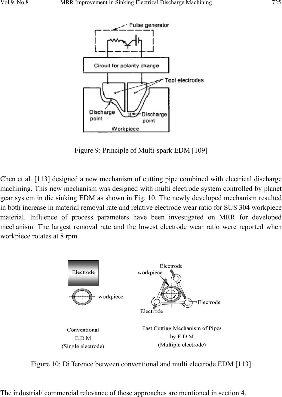 Vol.9, No.8 MRR Improvement in Sinking Electrical Discharge Machining 725 Figure 9: Principle of Multi-spark EDM [109] Chen et al. [113] designed a new mechanism of cutting pipe combined with electrical discharge machining. This new mechanism was designed with multi electrode system controlled by planet gear system in die sinking EDM as shown in Fig. 10. The newly developed mechanism resulted in both increase in material removal rate and relative electrode wear ratio for SUS 304 workpiece material. Influence of process parameters have been investigated on MRR for developed mechanism. The largest removal rate and the lowest electrode wear ratio were reported when workpiece rotates at 8 rpm. Figure 10: Difference between conventional and multi electrode EDM [113] The industrial/ commercial relevance of these approaches are mentioned in section 4. 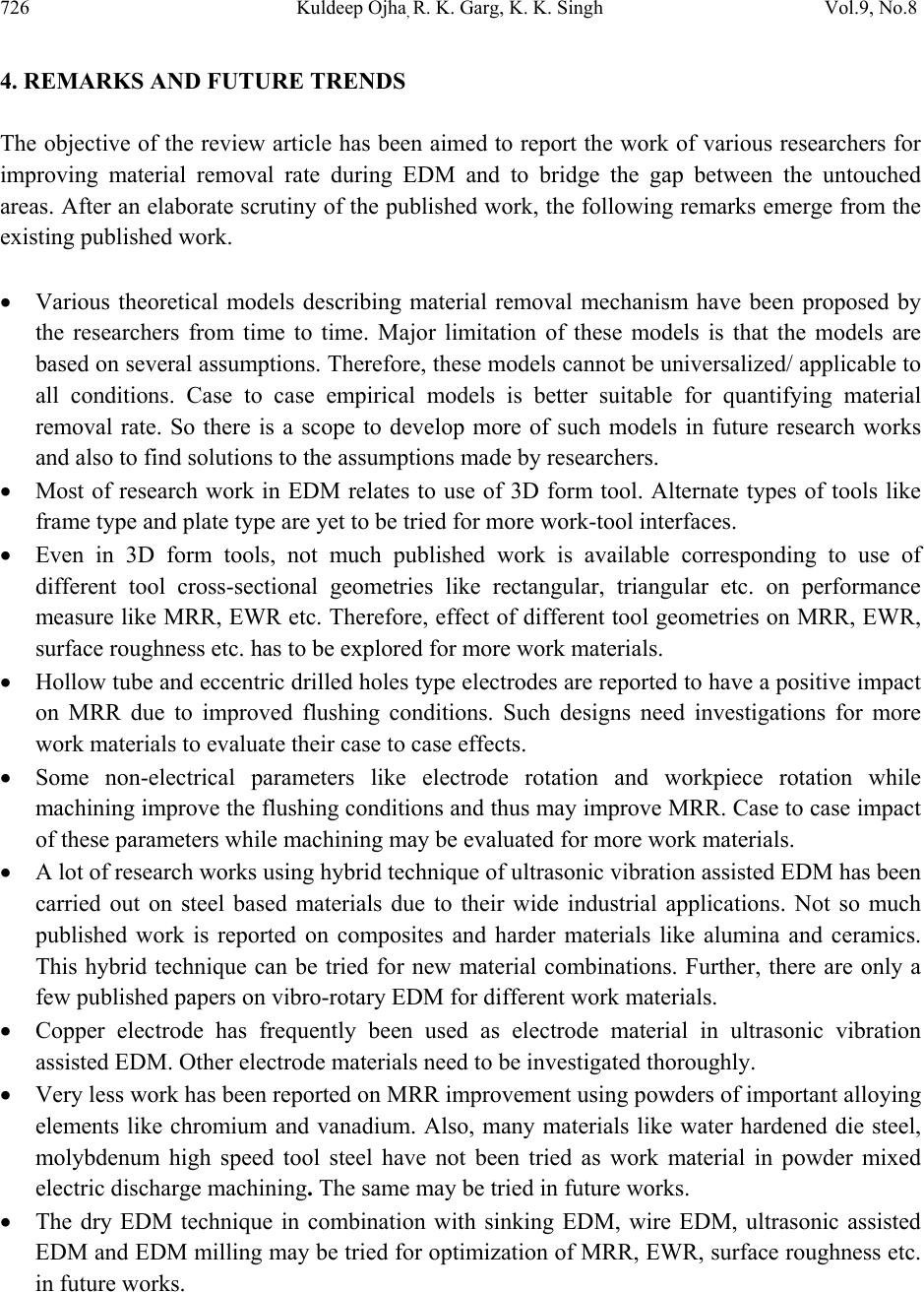 726 K ul deep Ojha, R. K. Garg, K. K. Singh Vol.9, No.8 4. REMARKS AND FUTURE TRENDS The objective of the review article has been aimed to report the work of various researchers for improving material removal rate during EDM and to bridge the gap between the untouched areas. After an elaborate scrutiny of the published work, the following remarks emerge from the existing published work. Various theoretical models describing material removal mechanism have been proposed by the researchers from time to time. Major limitation of these models is that the models are based on several assumptions. Therefore, these models cannot be universalized/ applicable to all conditions. Case to case empirical models is better suitable for quantifying material removal rate. So there is a scope to develop more of such models in future research works and also to find solutions to the assumptions made by researchers. Most of research work in EDM relates to use of 3D form tool. Alternate types of tools like frame type and plate type are yet to be tried for more work-tool interfaces. Even in 3D form tools, not much published work is available corresponding to use of different tool cross-sectional geometries like rectangular, triangular etc. on performance measure like MRR, EWR etc. Therefore, effect of different tool geometries on MRR, EWR, surface roughness etc. has to be explored for more work materials. Hollow tube and eccentric drilled holes type electrodes are reported to have a positive impact on MRR due to improved flushing conditions. Such designs need investigations for more work materials to evaluate their cas e to ca se ef fe ct s. Some non-electrical parameters like electrode rotation and workpiece rotation while machining improve the flushing conditions and thus may improve MRR. Case to case impact of these parameters while machining may be evaluated for more work materials. A lot of research works using hybrid technique of ultrasonic vibration assisted EDM has been carried out on steel based materials due to their wide industrial applications. Not so much published work is reported on composites and harder materials like alumina and ceramics. This hybrid technique can be tried for new material combinations. Further, there are only a few published papers on vibro-rotary EDM for different work materials. Copper electrode has frequently been used as electrode material in ultrasonic vibration assisted EDM. Other electrode materials need to be investigated thoroughly. Very less work has been reported on MRR improvement using powders of important alloying elements like chromium and vanadium. Also, many materials like water hardened die steel, molybdenum high speed tool steel have not been tried as work material in powder mixed electric discharge machining. The same may be tried in future works. The dry EDM technique in combination with sinking EDM, wire EDM, ultrasonic assisted EDM and EDM milling may be tried for optimization of MRR, EWR, surface roughness etc. in future works.  Vol.9, No.8 MRR Improvement in Sinking Electrical Discharge Machining 727 Performance of water based dielectric is yet to be investigated for machining materials like composites and carbides. Multi spark EDM and multi electrode EDM are relatively new techniques for MRR improvement and are still in experimental stage. More empirical validation using different workpiece materials is required before the method may be recommended for commercial applications. There is negligible published work available on comparative analysis of various EDM techniques of MRR improvement with same/different work materials in EDM. 5. SUMMARY In this paper, review of EDM research work related to MRR improvement has been presented along with some insight into the basic EDM process and material removal mechanism. The major research development resulting in improvement in material removal rate is summarized in Table 1in chronological order. It is found that the basis of controlling and improving MRR mostly relies on empirical methods. This is largely due to stochastic nature of the sparking phenomenon involving both electrical and non-electrical process parameters along with their complicated interrelationship. Being an important performance measure, the MRR has been getting overwhelming research potential since the invention of EDM process, and requires more study/experimentat ion /mod eli ng i n f utu re. Table 1: Major research development in chronological ord er r e su lt ing in MRR improvement Name of researchers Year Contribution Workpiece material Electrode material Parameters taken into account Electrical Non- electrical Bayramoglu and Duffill [40] 1995 Investigated frame type cutting tool with CNC EDM for generation of linear, circular and curved contours Mild steel Copper Voltage, current, on- time, off -time Non Ming and He [94] 1995 Investigated the effect of powder suspension in kerosene oil High carbon steel and high alloy steel Copper Current, pulse interval Non  728 K ul deep Ojha, R. K. Garg, K. K. Singh Vol.9, No.8 used as dielectric. Wong et al. [30] 1995 Investigated the influence of flushing on the efficiency and stability of machining condition. AISI 01 tool steel Copper Pulse current, pulse-on time, pulse-off time, gap voltage and polarity Flushing rate Kunieda and Yoshida [100] 1997 Investigated dry EDM method and compared its performance with EDM in oil. Steel (S45C) Copper Voltage, current, pulse duration, polarity Wall thickness of pipe electrode, air pressure, rotation and plenary motion of tool Wong et al. [87] 1998 Investigated the near- mirror-finish phenomenon in EDM with fine powder suspension in dielectric. SKH-54 tool steel copper Spark gap, pulse duration, polarity Powder suspension type and properties Chen et al. [108] 1999 Investigated machining characteristics with kerosene and distilled water as the dielectrics. Titanium alloy (Ti– 6A1–4V) Copper Current, pulse duration Type of dielectric fluid Wang and Yan [67] 2000 Compared the performance of stationary electrode, a rotational Al2O3/6061Al composite Copper polarity, peak current, pulse duration, Electrode rotation, flushing pressure  Vol.9, No.8 MRR Improvement in Sinking Electrical Discharge Machining 729 electrode, and a rotational electrode with an eccentric through-hole terms of machining characteristics supply voltage Kunieda and Muto [109] 2000 Investigated and compared machining characteristics of Multi-spark EDM electrode with those of conventional EDM electrode. steel SUJ2 Copper Voltage, current, polarity Non Aspinwall [81] 2001 Investigated hybrid high speed machining process (EDM/HSM). Steel Graphite Voltage Electrode rotation Tzeng and Lee [86] 2001 Investigated the effects of various powder characteristics on the efficiency of PMEDM. SKD11 Copper Spark gap, current, pulse-on time Powder suspension type Zhao et al. [85] 2002 Performed experimental research on machining efficiency and surface roughness of Steel Copper Current, pulse-on time, pulse-off time Non  730 K ul deep Ojha, R. K. Garg, K. K. Singh Vol.9, No.8 PMEDM in rough machining. Ghoreishi and Atkinson [77] 2002 Investigated and compared the effect of high and low frequency forced axial vibration, electrode rotation and combination of these methods on performance measures. Tool and die steel A1S1 01Copper Open voltage, discharge voltage, tool polarity Amplitude of ultrasonic and low frequency vibration, electrode rotation, Frequency of vibration Mohan et al. [69] 2004 Investigated effect of tube electrode rotation on performance measures. 6025 Al-alloy reinforced with SiC particles Brass Peak current, polarity, pulse duration Electrode rotation, volume fraction of SiC reinforced particles, hole diameter of tube electrode Bayramoglu and Duffill [66] 2004 Investigated plate type tool and compared the performance with 3 D form tool. Steel Copper Voltage, current, on- time, off -time Non Singh et al. [72] 2005 Optimize the process parameters of powder mixed electrical discharge machining by EN 31 tool steel Copper Pulse on time, duty cycle, peak current Concentration of the added silicon powder  Vol.9, No.8 MRR Improvement in Sinking Electrical Discharge Machining 731 using response surface methodology. Chen et al. [113] 2008 Introduced a new mechanism of cutting pipe combined with electrical discharge machining SUS 304 Copper Peak current, pulse duration, polarity Workpiece rotation Han et al. [80] 2009 Proposed a novel high- speed electrical discharge machining (EDM) milling method using moving electric arcs. Mold steel Copper Open voltage, peak current, duty cycle Electrode revolution Xu et al. [84] 2009 Proposed the tool electrode ultrasonic vibration assisted EDM in gas medium and introduced its principle. YT15 cemented carbide Copper Voltage, current pulse on- time Frequency and amplitude of ultrasonic vibration, Zhang et al. [104] 2002 Proposed and investigated ultrasonic vibration electrical discharge machining Steel Copper Voltage, pulse duration, Pipe wall thickness, electrode, vibration amplitude, effects of gas medium Kunieda et al. [102] 2003 Investigated high speed EDM milling of 3D cavities Mild steel (SS400) Copper Discharge current, discharge duration, Non  732 K ul deep Ojha, R. K. Garg, K. K. Singh Vol.9, No.8 using gas as the working fluid discharge interval Yu et al. [103] 2004 Compared machining characteristics between dry EDM milling, oil EDM milling and oil die sinking EDM Cemented carbide Copper tungsten Discharge current, discharge duration, discharge interval Electrode rotation Zhang et al. [78] 2006 Applied ultrasonic to improve the efficiency in EDM in gas medium AISI 1045 steel Copper Open voltage, pulse duration, discharge current Gas pressure, wall thickness, actuation amplitude REFERENCES [1] Ho, K.H., Newman, S.T., 2003 “State of the art electrical discharge machining (EDM)”, Int. J. Mach. Tools Manuf., 43, 1287–1300. [2] Kansal, H.K., Singh, P, Kumar, P., 2007, “Technology and research developments in powder mixed electric discharge machining (PMEDM)”, Journal of Materials Processing Technology, 184, 32–41. [3] Abu Zeid, O.A., 1997, “On the effect of electro-discharge machining parameters on the fatigue life of AISI D6 tool steel”. Journal of Materials Processing Technology, 68 (1), 27–32. [4] Ramasawmy, H., Blunt L., 2004 “Effect of EDM process parameters on 3D surface topography”, Journal of Materials Processing Technology, 148,155–164. [5] Rudorff, D.W., 1961 “Spark machining and its development”, Metal Treatment and Drop Forging, 28 (186), 120–124. [6] Pandey, P.C.; Shan, H.S. Modern Machining Process. Tata McGraw- Hill Publishing Company Ltd 1999, 84-113. [7] Smith, G.V., 1961, “Spark machining – fundamental and techniques. J Br Inst Radio Eng, 22, 409. [8] Luis, C.J., Puertas, I., Villa, G., 2005 “Material removal rate and electrode wear study on the EDM of silicon carbide”, Journal of Materials Processing Technology, 164–165, 889–  Vol.9, No.8 MRR Improvement in Sinking Electrical Discharge Machining 733 896. [9] Schumacher, B.M., 2004 “After 60 years of EDM, the discharge process remains still disputed. Journal of Materials Processing Technology”, 149, 376–381. [10] Singh, S., Maheshwari, S., Pandey, P.C., 2004 “Some investigations into the electric discharge machining of hardened tool steel using different electrode materials”, Journal of Materials Processing Technology, 149, 272–277. [11] Bojorquez, B., Marloth, R.T., Es-Said, O.S., 2002 “Formation of a crater in the workpiece on an electrical discharge machine”, Engineering Failure Analysis, 9, 93–97. [12] Marafona, J.; Chousal, A.G., 2006 “A finite element model of EDM based on the Joule effect”, Int. J. Mach. Tools Manuf., 46 (6), 595-602. [13] Kuneida, M., Lauwers, B., Rajurkar, K.P., Schumacher, B.M., 2005 “Advancing EDM through fundamental insight into the process”, Annals of CIRP, 54 (2), 599–622. [14] Altpeter, F., Perez, R., 2004 “Relevant topics in wire electrical discharge machining Control”, Journal of Materials Processing Technology, 149, 1-3, 147-151. [15] McGeough, J.A. Advanced Methods of Machining. 1st ed. Chapman and Hall, USA, 1988, ISBN 0- 412-31970-5. [16] Zingerman, A.S., 1956 “Propagation of a discharge column”. Soviet Physics-Technical Physics, 1(1), 5, 992-996. [17] Snoeys, R., Van Dijck, F., 1971, “Investigations of EDM operations by means of thermo mathematical models”, Annals of the CIRP, 20, 35-36. [18] Snoeys, R., Van Dijck, F., 1972, “Plasma channel diameter growth affects stock removal in EDM”, Annals of the CIRP, 21, 39-40. [19] Eckman P.K., Williams E.M., 1960, “Plasma dynamics in arc formed by low-voltage spark over of a liquid dielectric”, Appl. Sci. Res., Section B, 8, 299-320. [20] Ikeda, M., 1972, “The Movement of a bubble in the gap depending on the single electrical discharge (1st report)”, J. JSEME, 6, 11, 12-25 (in Japanese). [21] Zolotykh, B.N., 1959 “The mechanism of electrical erosion of metals in liquid dielectric media. Soviet Physics-Technical Physics, 4, 12, 1370-1373. [22] Hockenberry T.O., Williams E.M., 1967, “Dynamic evolution of events accompanying the low-voltage discharge employed in EDM”, IEEE Trans. on Industry and General Applications, IGA-3, 4, 302-309. [23] Rajurkar, K.P., 1994, Handbook of Design, Manufacturing and Automation, ISBN- 0471552186 Chapter 13: Nontraditional Manufacturing Processes, Wiley, USA. [24] Pandit, S.M., Mueller, T.M., 1987 “Verification of on-line computer control of EDM by data dependent systems”, J. Eng. Ind., 109, 109–121. [25] Lin, C.L., Lin, J.L., Ko, T.C., 2002, “Optimization of the EDM process based on the orthogonal array with fuzzy logic and grey relational analysis method”, International Journal of Advance Manufacturing Technology, 19 (4), 271–277.  734 K ul deep Ojha, R. K. Garg, K. K. Singh Vol.9, No.8 [26] Lin, J.L., Wang, K.S., Yan, B.H., Tarng, Y.S., 2000, “Optimization of the electrical discharge machining process based on the Taguchi method with fuzzy logics”, Journal of Materials Processing Technology, 102, 48–55. [27] Tzeng, Y.F., Chen, F.C., 2003, “A simple approach for robust design of high-speed electrical discharge machining technology”, Int. J. Mach. Tools Manuf., 43(3), 217–227. [28] Marafona, J., Wykes, C., 2000, “A new method of optimizing material removal rate using EDM with copper tungsten electrodes”, Int. J. Mach. Tools Ma n u f., 40(2), 153–164. [29] Lonardo, P.M., Bruzzone, A., 1999, “Effect of flushing and electrode material on die sinking EDM”, CIRP Annals - Manufacturing Technology, 48 (1), 123– 126. [30] Wong, Y.S., Lim, L.C., Lee, L.C., 1995, “Effect of flushing on electro-discharge machined surfaces”, Journal of Materials Processing Technology, 48, 299–305. [31] Anonymous, 1982, “Dielectric Fluids for Electro d ischarge Machining”, British Petroleum Company, UK. [32] Guu, Y.H., Hocheng, H., 2001, “Effects of workpiece rotation on machinability during electrical discharge machining”, Journal of Material and Manufacturing Processes, 16 (1), 91–101. [33] Soni, J.S., Chakraverty, G., 1994, “Machining characteristics of titanium with rotary electro-discharge machining”, Wear, 171, 51–58. [34] Yan, B.H., Wang, C., Liu, W.D., Huang, F.Y., 2000 “Machining characteristics of Al2O3/6061Al composite using rotary EDM with a disklike electrode”, International Journal of AdvanceManufacturing Technology, 16 (5), 322–333. [35] Kagaya, K., Oishi, Y., Yada, K., 1986, “Micro-electro discharge machining using water as a working fluid—I: micro-hole drilling”, Precision Eng., 8 (3), 157–162. [36] Sato, T., Mizutani, T., Yonemochi, K., Kawata, K., 1986, “The development of an electro discharge machine for micro-hole boring”, Precision Engineering, 8 (3), 163–168. [37] Soni, J.S., Chakraverti, G., 1996, “Experimental investigation on migration of material during EDM of T 215 Cr12 die steel”, Journal of Materials Processing Technology, 56, 439–451. [38] Roethel, F., Kosec, L., Garbajs, V., 1976, “Contributions to the micro-analysis of spark eroded surfaces”, Annals of the CIRP, 25 (1), 135–140. [39] Erden, A., 1983, “Effect of materials on the mechanism of electric discharge machining (EDM)”, J. Eng. Mater. Technol., 105, 132–138. [40] Bayramoglu, M., Duffill, A.W., 1995, “Manufacturing linear and circular contours using CNC EDM and frame type tools”, Int. J. Mach. Tools Manuf., 35(8), 1125–1136. [41] Bayramoglu, M., Duffill, A.W., 1992, “Production of three dimensional shapes using computational electrical discharge machining”, In Proc. Int. M.T.D.R. conf., pp 107-112. [42] Saito, K., Kishinami, T., Konno, H., Sato, M., Takeyama, H., 1986, “Development of numerical contouring control electrical discharge machining (NCC-EDM)”, Ann. CIRP, 35 (1), 117–120. [43] Kaneko, T., Tsuchiya, M., 1984, “Three dimensionally controlled EDM using cylindrical  Vol.9, No.8 MRR Improvement in Sinking Electrical Discharge Machining 735 electrode”, J. Japan Soc. Electr. Machining Eng., 18 (35), 1–4. [44] Mohri, N., Suzuki, M., Furuya, M., Saito, N., 1995, “Electrode wear process in electrical discharge machining”, Ann. CIRP, 44 (1), 165–168. [45] Snoeys, R., Staelens, F., Dekeyser, W., 1986, “Current trends in non-conventional machining techniques”, Ann. CIRP, 35 (2), 467– 480. [46] Staelens, F., Kruth, J.P., 1989, “A computer integrated machining strategy for planetary EDM”, Ann. CIRP, 38 (1), 187–190. [47] Schumacher, B.M., 1983, “EDM technology for precision workpieces with excellent surface quality”, Proceedings of the ISEM-7, 124–135. [48] Dijck, F.V. Physico-mathematical analysis of the electro dicharge machining process. Ph.D. Thesis Katholieke Universiteit te Leuven. Around 1972. [49] Dibitonto, D.D., Eubank, P.T., Patel, M.R., Barrufet, M.A., 1989, “Theoretical models of the electrical discharge machining process- 1: a simple cathode erosion model”, Journal of Applied Physics, 66, 4095- 4103. [50] Patel, M. R., Barrufet, M.A., Eubank, P.T., Dibitonto, D.D., 1989 “Theoretical models of the electrical discharge machining process- II: the anode erosion model”, Journal of Applied Physics, 66, 4104-4111. [51] Eubank P.T., Patel M.R., Barrufet M.A., Bozhurt B., 1993, “Theoretical models of the electrical discharge machining process- III: The variable mass, cylindrical plasma model”, Journal of applied physics, 73 (1), 11, 7900-7909. [52] Singh, A., Ghosh, A., 1999, “A thermo-electric model of material removal during electric discharge machining”, Int. J. Mach. Too ls Manuf., 39 (4), 669–682. [53] Gangadhar, A., Sunmugam, M.S., Philip, P.K., 1992, “Pulse train studies in EDM with controlled pulse relaxation”, Int. J. Mach. Tools Manuf., 32 (5), 651–657. [54] Gadalla, A.M., Tsai, W., 1989, “Machining of WC–Co composites”, Mater. Manuf. Processes, 4 (3), 411– 423. [55] Lee, T.C., Lau, W.S., 1991, “Some characteristics of electrical discharge machining of conductive ceramics”, Mater. Manuf. Processes, 6 (4), 635–648. [56] Soni J.S., Chakraverti, G., 1990 “Production of surface finish and accuracies with rotating electrode in electro-discharge machining”, Proc. Conf. 14th AIMTDR, IIT Bombay, 297. [57] Soni, J.S., Chakraverti, G., 1990, “Physico-mechanical effect on electro-discharge machined surface of high carbon high chromium die steel”, J of Inst. of Engineers (India), PR, Vol. 71, July, p.19. [58] Soni, J.S., Chakraverti G., 1991, “Micro examination of craters and debris formed on EDM surfaces”, J of Metals, Materials and Processes, 3, 3, 177. [59] Soni, J.S., Chakraverti, G., 1990, “Cracking behavior of high carbon high chromium tool steel duringEDM-a study”, Proc. Conf. 14th AIMTDR, IIT, Bombay, p. 263. [60] Ayers, J.D., Moore Kathy, 1984, “Formation of metal carbide powder by spark machining of reactive metals”, Metallurgical Transactions, 15A, 1117.  736 K ul deep Ojha, R. K. Garg, K. K. Singh Vol.9, No.8 [61] Koshy George, Philip, P.K., Geddam A., 1981 “Hardening of surface layers using electric discharge techniques”, Proc. Conf. llth AIMTDR, IIT, Madras, p. 315. [62] Pandey, P.C., Jilani, S.T., 1986, “Plasma channel growth and the re solidified layer in EDM”, Prec. Eng., 8, 2, p. 104 [63] Gupta, R.P. “A study of the isopulse spark eroded surfaces of some tool steels. Proc. Conf. 10th AIMTDR, U.K., 1982, p. 351. [64] Crookall J.R.; Khor, B.C. “Residual Stresses and surface effects in electro-discharge machining. Proc. Conf. 13th IMTDR, 1972, p. 331. [65] Gangadhar, A.; Shunmugam M.S.; Philip, P.K., 1991, “Surface modification in electro discharge processing with a powder compact tool electrode. Wear, 143, 1, p. 45. [66] Bayramoglu, M.; Duffill, A.W., 2004, “CNC EDM of linear and circular contours using plate tools”, Journal of Materials Processing Technology, 148, 196–203. [67] Wang, C.C., Yan, B.H., 2000, “Blind-hole drilling of Al2O3/6061Al composite using rotary electro-discharge machining”, Journal of Materials Processing Technology, 102, 90–102. [68] Mohan B., Rajadurai A., Satyanarayan K.G., 2002, “Effect of SiC and rotation of electrode on electric discharge machining of Al-SiC composite”, Journal of Materials Processing Technology, 124, 297–304. [69] Mohan B., Rajadurai A., Satyanarayana K.G., 2004, “Electric discharge machining of Al– SiC metal matrix composites using rotary tube electrode”. Journal of Materials Processing Technology, 153–154, 978–985. [70] Sohani, M.S., Gaitonde, V.N., Siddeswarappa, B, Deshpande, A.S., 2009, “Investigations into the effect of tool shapes with size factor consideration in sink electrical discharge machining (EDM) process”, International Journal of Advance Manufacturing Technology, 45, 1131–1145. [71] Kansal, H.K., Singh, S., Kumar, P., 2005, “Application of Taguchi method for optimization of powder mixed electric discharge machining”, International Journal of Management and Manufacturing Technology, 7, 329–341, Nos. 2/3/4. [72] Singh, S., Kansal, H.K., Kumar, P., 2005, “Parametric optimization of powder mixed electrical discharge machining by response surface methodology”, Journal of Materials Processing Technology, 169 (3), 427– 436. [73] De Bruyn, H.E., 1970, “Some aspects of the influence of gap flushing on the accuracy in finishing by spark e rosion”, Annals of the CIRP, 18, 147-151. [74] Masuzawa, T., Cui X., Taniguchi, N., 1992 “Improved jet flushing for EDM”, Annals of the CIRP, 41/1, 239-242. [75] Konig, W., Weill, R., Wertheim, R., Jutzler, W.I., 1977, “The flow fields in the working gap with electro-discharge-machining”. Annals of the CIRP, 25(1), 71-76. [76] Guo, Z.N., Lee, T.C., Yue, T.M., Lau, W.S., 1997 “A study of ultrasonicaided wire electrical discharge machining”, Journal of Materials Processing Technology, 63, 823– 828.  Vol.9, No.8 MRR Improvement in Sinking Electrical Discharge Machining 737 [77] Ghoreishi, M., Atkinson, J., 2002, “A comparative experimental study of machining characteristics in vibratory, rotary and vibro-rotary electro-discharge machining”, Journal of Materials Processing Technology, 120, 374–384. [78] Zhang, Q.H., Du, R., Zhang, J.H., Zhang, Q., 2006, “An investigation of ultrasonic-assisted electrical discharge machining in gas”, Int. J. Mach. Tools Manuf., 46, 1582–1588. [79] Gunawan S, Prihandana, Hamdi, M., Wong, Y.S., Mitsui, K., 2006 “Effect of vibrated electrode in electrical discharge machining”, Proceedings of the First International Conference and Seventh AUN/SEED-Net Fieldwise Seminar on Manufacturing and Material Processing, 14–15 March 2006, Kuala Lumpur, pp. 133–138. [80] Han, F., Wang, Y., Zhou, M., 2009 “High-speed EDM milling with moving electric arcs”, Int. J. Mach. Tools Manuf., 49, 20–24 [81] Aspinwall, D.K., Dewes, R.C., Burrows, J.M., Paul, M.A., 2001 Hybrid high speed machining (HSM): system design and experimental results for grinding/HSM and EDM/HSM. Ann. CIRP, 50 (1), 145–148. [82] Suzuki, K., Uematsu, T., Asano, S., Yanase, T., Sakai, S., Ohkawa, K., 1988, Electro discharge machining on a machining centre, Research an Technological Developments in Nontraditional machining ASME, Winter Annual Meeting of the ASME, Chicago, IL, USA, PED-34, 1-5. [83] Altan, T., Lilly, B.W., Kruth, J.P., Konig, W., Tonshoff, H.K., Van Luttervelt, C.A., Khairy, A.B., 1993, “Advanced techniques for die and mold manufacturing”, Annals of the CIRP, 42(2), 707-716. [84] Xu, M.G.; Zhang, J.H.; Yule; Zhang, Q.H.; Ren, S.F., 2009 “Material removal mechanisms of cemented carbides machined by ultrasonic vibration assisted EDM in gas medium”, Journal of materials processing technology, 209, 1742–1746. [85] Zhao, W.S., Meng, Q.G., Wang, Z. L. 2002, “The application of research on powder mixed EDM in rough machining”, Journal of mat eri als p roc ess ing te chn olo gy, 129, 30–33. [86] Tzeng, Y.F., Lee, C.Y., 2001, “Effects of powder characteristics on electro discharge machining efficiency”, Int. J. Adv. Manuf. Technol., 17, 586–592. [87] Wong, Y.S., Lim, L.C., Rahuman, I., Tee, W.M., 1998, “Near-mirror-finish phenomenon in EDM using powder-mixed dielectric”, Int. J. Adv. Manuf. Technol., 79, 30–40. [88] Furutani, K., Saneto, A., Takezawa, H., Mohri, N., Miyake, H., 2001, “Accretion of titanium carbide by electrical discharge machining with powder suspended in working fluid”, Precis. Eng., 25, 138–144. [89] Erden, A., Bilgin, S., 1980, “Role of impurities in electric discharge machining”, in: Proceedings of 21st International Machine Tool Design and Research Conference, Macmillan, Lon don, 1980, pp.345–350. [90] Jeswani, M.L., 1981, “Effects of the addition of graphite powder to kerosene used as the dielectric fluid in electrical discharge machining”, Wear, 70, 133–139. [91] Yan, B.H., Chen, S.L., 1993, “Effects of dielectric with suspended aluminum powder on EDM”, J. Chin. Soc.Mech. Eng., 14 (3), 307–312.  738 K ul deep Ojha, R. K. Garg, K. K. Singh Vol.9, No.8 [92] Yan, B.H., Chen, S.L., 1994, “Characteristics of SKD11 by complex process of electric discharge machining using liquid suspended with aluminum powder”, Jpn. Inst. Light Met., 58 (9) 1067–1072. [93] Yan, B.H., Chen, S.L., 1994, “Effect of ultrasonic vibration on electrical discharge machining characteristics of Ti–6Al–4V alloy”, J. Jpn. Inst. Light Met., 4 4 (5), 281–285. [94] Ming, Q.Y., He, L.Y., 1995, “Powder-suspension dielectric fluid for EDM”, Journal of materials processing tec h n ology, 52, 44–54. [95] Yu, C.P., Chen, W.C., Chang, S.W., Chang, C.C., 1996, “Effects of the concentration of suspended aluminum powder in dielectric fluid on EDM of carbide of tungsten’s”, in: Proceedings of the 13th conference of Chinese Society of Mechanical Engineers, Taiwan, pp. 445–450. [96] Wang, C.H., Lin, Y.C., Yan, B.H., Huang, F.Y., 2001, “Effect of characteristics of added powder on electric discharge machining”, J. Jpn. Inst. Light Met., 42 (12), 2597–2604. [97] Tani, T., Fukazawa, F., Mohri, N., Okada, M., 2001, “Machining phenomena in EDM of insulating ceramics using powder suspended working oil”, In: 12th ISEM Bilbao, pp. 388– 392. [98] Rozenek, M., Kozak, J., Dabrowski, L., 2001, “Study of electrical discharge machining using powder suspended working media”, In: 12th ISEM Bilbao, pp. 351–357. [99] Pecas, P., Henriques, E.A., 2002, “Emerging technologies in penetration EDM”, O Molde, 55, 26–36. [100] Kunieda, M., Yoshida, M., 1997, “Electrical discharge machining in gas”, CIRP Annals – Manufacturing Technology”, 46(1), 143-146 [101] Kunieda, M., Furuoya, S., Taniguchi, N., 1991, “Improvement of EDM efficiency by supplying oxygen gas into gap”, CIRP Annals—Manufacturing Technology, 40, 215–218. [102] Kunieda, M., Miyoshi, Y., Takaya, T., Nakajima, N., Bo, Y.Z., Yoshida, M., 2003, “High speed 3D milling by dry EDM”, CIRP Annals—Manufacturing Technology, 52, 147–150. [103] Yu, Z.B., Jun, T., Masanori K., 2004, “Dry electrical discharge machining of cemented carbide”, Journal of Materials Processing Technology, 149, 353–357. [104] Zhang, Q.H., Zhang, J.H., Deng, J.X., Qin, Y., Niu, Z.W., 2002, “Ultrasonic vibration electrical discharge machining in gas”, Journal of Materials Processing Technology, 129, 135–138. [105] Jeswani M.L., 1981, “Electrical discharge machini ng in distilled water”, Wear, 72, 81–88. [106] Tariq Jilani, S., Pandey, P.C., 1984, “Experimental investigations into the performance of water as dielectric in EDM”, International Journal of Machine Tool Design and Research, 24, 31–43. [107] Konig, W., Siebers F.J., 1993, “Influence of the working medium on the removal process in EDM sinking”, American Society of Mechanical Engineers, Production Engineering Division (Publication) PED, 64, 649–658.  Vol.9, No.8 MRR Improvement in Sinking Electrical Discharge Machining 739 [108] Chen, S.L., Yan, B.H., Huang, F.Y., 1999, “Influence of kerosene and distilled water as dielectric on the electric discharge machining characteristics of Ti-6Al-4V”, Journal of Materials Processing Technology, 87, 107–111. [109] Kunieda, M., Muto, H., 2000, “Development of multi-spark EDM”, Ann. CIRP, 49 (1), 119–122. [110] Mohri, N., Saito, N., Takawashi, T., Kobayashi, K., 1985 “Mirror-like finishing by EDM”, Proc. of the 25th MTDR Conf., 329–336 [111] Suzuki, K., Mohri, N., Uematsu, T., Nakagawa, T., 1985, “ED truing method with twin electrodes”, Preprint of Autumn Meeting of JSPE 1985, 575-578 (in Japanese). [112] Kubota, M., Tamura, Y., Okita, T., 1989 “Electrocontact discharge dr ess in g of metal bonded diamond grinding wheels using twin electrode system”, Proc. of ISEM 9, pp. 22– 25 [113] Chen, S.L., Lin, M.H., Hsieh, S.F., Chiou. S.Y., 2008, “The characteristics of cutting pipe mechanism with multi-electrodes in EDM”, Journal of materials processing technology, 203, 461– 464. |