Paper Menu >>
Journal Menu >>
 Journal of Mi nerals & Materials Characteriza tion & Engineering, Vol. 9, No.7, pp.643-652, 2010 jmmce.org Printed in t he USA. All rights reserved 643 Experimental Investigation of Woven E-Glass Epoxy Composite Laminates Subjected to Low-Velocity Impact at Different Energy Levels N. Rajesh Mathivanan*, J. Jerald Department of Production Engineering, National Institute of Technology, Tiruchirappalli - 15, India * Corresponding Author: rajesh_mathi@yahoo.com ABSTRACT This work presents the results of an experimental investigation concerning the low-velocity impact response of woven glass fiber epoxy matrix composite laminates. Experimental tests were performed according to ASTM standards using an instrumented falling weight impact testing machine. Impact tests were conducted to characterize the type and extent of the damages observed in laminate subjected to different impact velocities: 2 to 4.5 m/sec. The response of these laminates to drop-weight low velocity impact at energ y levels ranging from 3 to 15 J was investigated. At impact velocity of 4.429 m/sec, there is clearly a catastrophic failure of laminates. It was found that the laminates exhibited two types of failure modes viz., crack initiation and perforation of the laminate. Keywords: Composite laminates; Low-velocity impact; Impact testing 1. INTRODUCTION A composite material is a macroscopic combination of two or more distinct materials, having a recognizable interface between them. Composite laminate is a combination of fiber and resin mixed in proper form. One of the unique properties of composite laminate is that it has high specific strength. Composites are being utilized as viable alternatives to metallic materials in structures where weight is a major consideration, e.g., aerospace structures, high- speed boats and trains. However, their behavior under impact loading is one of the major concerns [1], since impacts do occur during manufacture, normal operations, maintenance and so on. A list of the studies on the impact response of composite materials and structures can be found in previous literatures [2-4]. The resulting damage due to impacts, often in the form of delaminations, matrix cracking and fiber failures may severely reduce the structural strength and stability. Even though fiber breakage is the ultimate failure mode, the damage  644 N. Rajesh Mathivana n, J. Jerald Vol.9, No.7 would initiate in the form of matrix cracking/lamina splitting and would lead to delamination. Damage-free composites are necessary for their effective use [5]. Low-velocity impact is considered potentially dangerous mainly because the damage might be left undetected. In many situations, the level of impact at which visible damage is formed is much higher than the level at which substantial loss of residual properties occurs. Impact damage is generally not considered to be a threat in metal structures because, owing to the ductile nature of the material, large amounts of energy may be absorbed. At yield stress the material may flow for very large strains (up to 20%) at constant yield before work hardening. In contrast, composites can fail in a wide variety of modes and contain barely visible impact damage (BVID) which nevertheless severely reduces the structural integrity of the component. Most composites are brittle and so can only absorb energy in elastic deformation and through damage mechanisms, and not by plastic deformation. Z.Y. Zhang et al. [6] revealed that there was a significant reduction in flexural properties due to the impact- induced damage and that the residual flexural strength is more susceptible to damage than residual modulus. A number of studies are available on the impact behavior of unidirectional laminated composites. Even though there are some studies on the impact behavior of woven fabric composites [7-13], further studies are necessary for their effective use in structural applications. The main goal of this work is to present and discuss some experimental results obtained during a low-velocity impact testing conducted on glass fiber epoxy matrix laminates. The impact behavior of this particular class of composite material is then analyzed from an energy viewpoint, by means of two parameters [14]: the saturation impact energy and the damage degree of a plate specimen subjected to a drop-dart test according to the ASTM D3029 standard. The drop dart tests have been conducted selecting different levels of the dart kinetic energy at impact by modification of the drop height. Thus, impact velocities are different in one test from the other and, consequently, the material of the plates is submitted to different deformation rate 2. EXPERIMENTAL MATERIALS AND METHODS 2.1 Specimen Fabrication The tested material was woven glass fiber epoxy matrix composite laminates of EP3 grade. Fiber reinforcement was kept constant for each batch of plates. Woven ‘E’ glass fabric, type C of IS: 11273 were used to fabricate composite laminates. An epoxy matrix based on Lapox L-12 resin and K-5 hardener was selected for making composite panels. The volume fraction of glass fibers is approximately 65%. Identical woven fabric layers were selected depending on the thickness of the composite laminates and fabricated by hand lay-up process. The composite panels were first cured at room temperature for 12 h under a pressure of 0.2MPa using a hydraulic press. The post-curing were carried out at 1200C for 4 h and then cooled to room temperature. 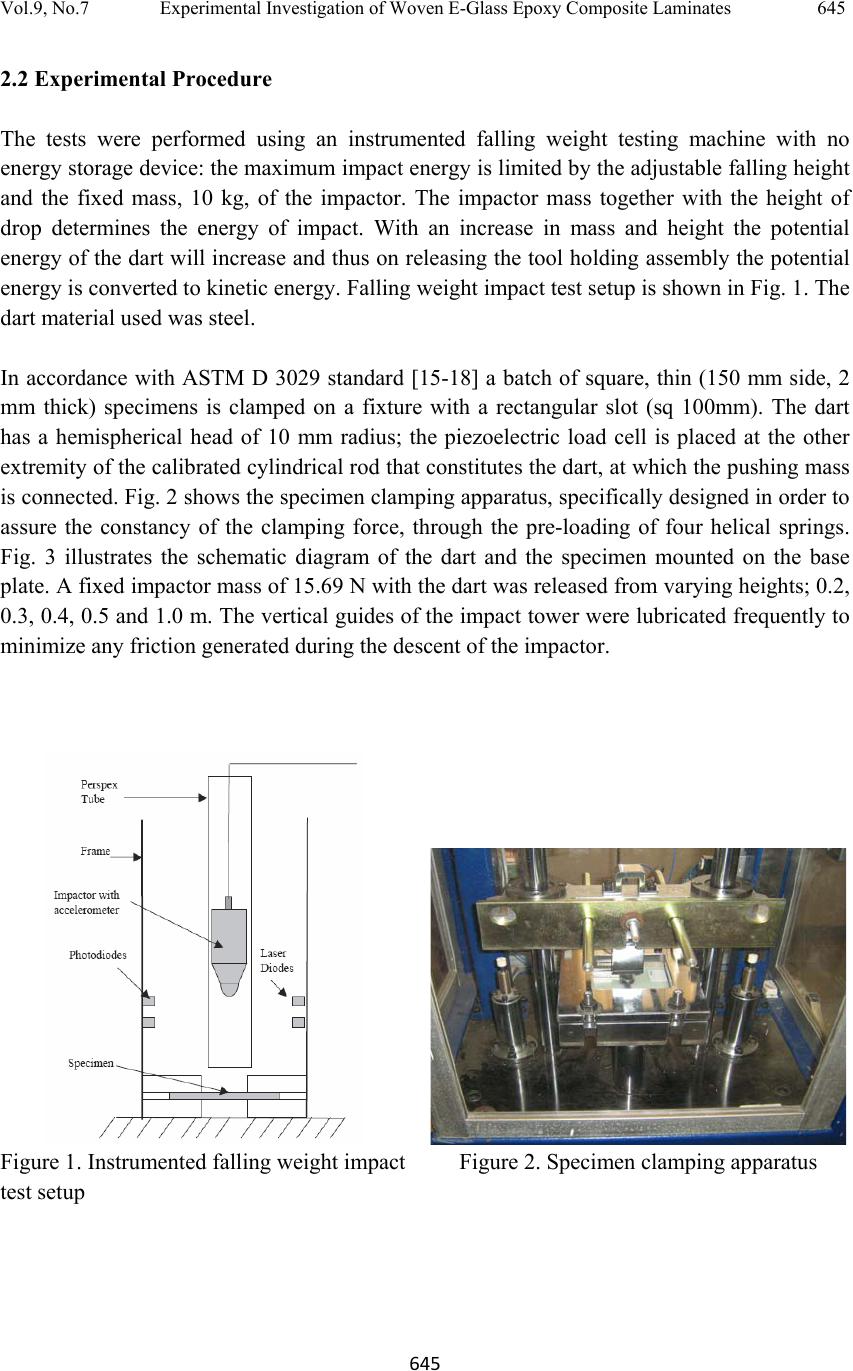 Vol.9, No.7 Experimental Investigation of Woven E-Glass Epoxy Composite Laminates 645 645 2.2 Experimental Procedure The tests were performed using an instrumented falling weight testing machine with no energy storage device: the maximum impact energy is limited by the adjustable falling height and the fixed mass, 10 kg, of the impactor. The impactor mass together with the height of drop determines the energy of impact. With an increase in mass and height the potential energy of the dart will increase and thus on releasing the tool holding assembly the potential energy is converted to kinetic energy. Falling weight impact test setup is shown in Fig. 1. The dart material used was steel. In accordance with ASTM D 3029 standard [15-18] a batch of square, thin (150 mm side, 2 mm thick) specimens is clamped on a fixture with a rectangular slot (sq 100mm). The dart has a hemispherical head of 10 mm radius; the piezoelectric load cell is placed at the other extremity of the calibrated cylindrical rod that constitutes the dart, at which the pushing mass is connected. Fig. 2 shows the specimen clamping apparatus, specifically designed in order to assure the constancy of the clamping force, through the pre-loading of four helical springs. Fig. 3 illustrates the schematic diagram of the dart and the specimen mounted on the base plate. A fixed impactor mass of 15.69 N with the dart was released from varying heights; 0.2, 0.3, 0.4, 0.5 and 1.0 m. The vertical guides of the impact tower were lubricated frequently to minimize any friction generated during the descent of the impactor. Figure 1. Instrumented falling weight impact test setup Figure 2. Specimen clamping apparatus  646 N. Rajesh Mathivana n, J. Jerald Vol.9, No.7 Figure 3. Schematic diagram of specimen being impacted 3. RESULTS AND DISCUSSIONS The E-glass composite specimens were subjected to low-velocity impact at different impact velocities; 1.981 to 4.429 m/sec, the thickness of the laminate were maintained constant at 2 mm. For each impact, the position and acceleration of the impactor were continuously monitored. The incident energy was calculated based on the height history, while the dissipation of energy was derived from both acceleration and height histories of the impactor, assuming rigid-body motion. A number of tests were performed under varied impact energies ranging from approximately 3.14 to 15.7 J. Therefore, in the following the force- displacement curves and the images of damaged specimens are discussed. Table 1 indicates the impact energy calculated for woven glass fiber epoxy matrix composite laminates. The mass of the impactor was kept constant at 15.69 N. Table 1. Summary of the calculated impact energy Spec. No Height of fall m Impact velocity m/sec Impact energy Joules Max load N Retardation at max load m/s ec2 Penetration at max load mm Energy at max lo ad Joules 201 0.2 1.981 3.14 1264.5 -780.502 -16.002 3.039 202 0.3 2.426 4.71 1620 -1002.69 -17.019 4.602 203 0.4 2.801 6.28 1849.5 -1146.127 -17.581 6.151 204 0.5 3.132 7.85 1822.5 -1129.252 -15.596 7.696 205 1.0 4.429 15.7 1755 -1087.065 -6.317 13.01 Fig. 4(i) illustrates the histories of the force and deformation energy. If the energy absorbed by the specimen is not too high a rebound occurs. Energy profile and damage process impact energy (Ei) and absorbed energy (Ea) are two main parameters that can be used to assess damage process in composite structures after an impact event. Ei can be defined as the kinetic energy of the impactor right before contact-impact takes place while Ea is termed as the 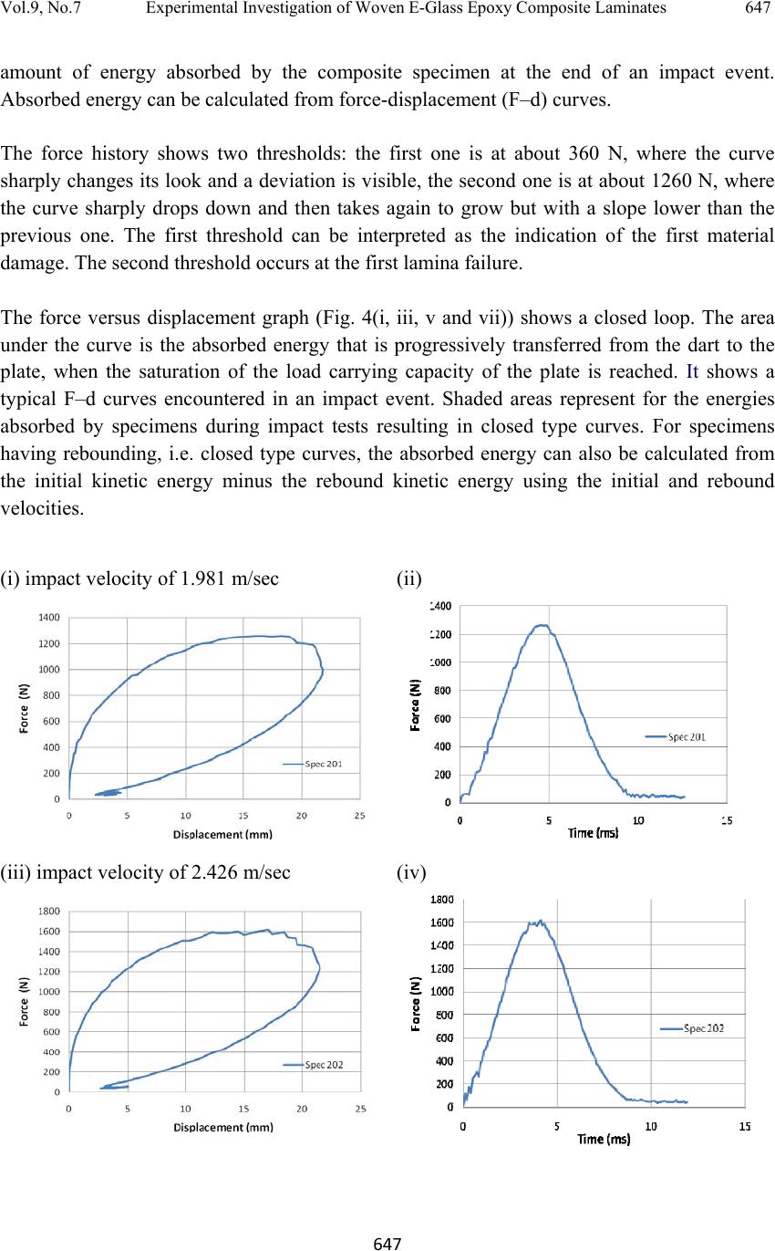 Vol.9, No.7 Experimental Investigation of Woven E-Glass Epoxy Composite Laminates 647 647 amount of energy absorbed by the composite specimen at the end of an impact event. Absorbed energy can be calculated from force-displacement (F–d) curves. The force history shows two thresholds: the first one is at about 360 N, where the curve sharply changes its look and a deviation is visible, the second one is at about 1260 N, where the curve sharply drops down and then takes again to grow but with a slope lower than the previous one. The first threshold can be interpreted as the indication of the first material damage. The second threshold occurs at the first lamina failure. The force versus displacement graph (Fig. 4(i, iii, v and vii)) shows a closed loop. The area under the curve is the absorbed energy that is progressively transferred from the dart to the plate, when the saturation of the load carrying capacity of the plate is reached. It shows a typical F–d curves encountered in an impact event. Shaded areas represent for the energies absorbed by specimens during impact tests resulting in closed type curves. For specimens having rebounding, i.e. closed type curves, the absorbed energy can also be calculated from the initial kinetic energy minus the rebound kinetic energy using the initial and rebound velocities. (i) impact velocity of 1.981 m/sec (ii) (iii) impact velocity of 2.426 m/sec (iv) 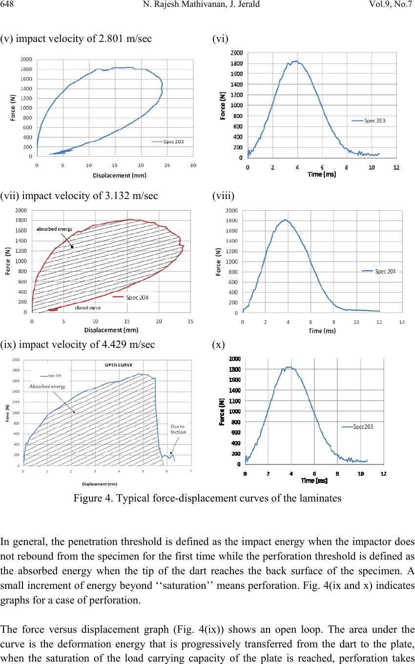 648 N. Rajesh Mathivana n, J. Jerald Vol.9, No.7 (v) impact velocity of 2.801 m/sec (vi) (vii) impact velocity of 3.132 m/sec (viii) (ix) impact velocity of 4.429 m/sec (x) Figure 4. Typical force-displacement curves of the laminates In general, the penetration threshold is defined as the impact energy when the impactor does not rebound from the specimen for the first time while the perforation threshold is defined as the absorbed energy when the tip of the dart reaches the back surface of the specimen. A small increment of energy beyond ‘‘saturation’’ means perforation. Fig. 4(ix and x) indicates graphs for a case of perforation. The force versus displacement graph (Fig. 4(ix)) shows an open loop. The area under the curve is the deformation energy that is progressively transferred from the dart to the plate, when the saturation of the load carrying capacity of the plate is reached, perforation takes  Vol.9, No.7 Experimental Investigation of Woven E-Glass Epoxy Composite Laminates 649 649 place. At this instant the maximum energy absorbed by the material damage mechanisms is read. Open type F–d curves have a horizontal section at the very end, post-perforation frictional section. In order to identify the true energy absorption due to damage formation in the specimens, the post-perforation frictional sections need to be removed from the curves. For this purpose, the ending part of the descending section of the F–d curve may be extended to the displacement axis. Specimens have been examined after the impact test with the aim of establishing a correlation between the test conditions and the plate damage. For comparison, images of the damaged specimens are given in figure 5. Damage extent at both front (impacted) and back side of the specimens are given. For a low energy level (falling height up to 500 mm, velocity at the impact 3.132 m/s), this fiber layout shows good impact resistance characteristics: almost all the energy is released back to the rebounding dart. The maximum energy is reached at about 7.85 J. Specimen 205 exhibit complete perforations when compared with other specimens. The post impact examination reveals that the specimen 205 does not offer significant support under impact loading conditions. At impact velocity of 4.429 m/sec, there is clearly a catastrophic failure of laminates. Failure modes of the laminates were evaluated through visual inspection. It is evident that clearly two types of failure modes were identified viz., crack initiation and perforation of the laminate.  650 N. Rajesh Mathivana n, J. Jerald Vol.9, No.7 Figure 5. Post-impact images of damaged specimens 4. CONCLUSIONS The behavior of woven glass epoxy laminates were subjected to low-velocity impact loading at different energy levels have been investigated using standard instrumented falling weight test. These tests have shown that the dynamic response of these systems depends on the elastic properties of the fiber material. The force versus displacement and the time versus force  Vol.9, No.7 Experimental Investigation of Woven E-Glass Epoxy Composite Laminates 651 651 curves for each case have been drawn. The glass epoxy laminates exhibited two types of failure modes viz., crack initiation and perforation. At impact velocity up to 3.132 m/sec, the laminate sustained the impact with delamination on the outer layer. Whereas, at impact velocity of 4.429 m/sec, there is clearly a catastrophic failure of laminates, perforation of the laminate was observed. ACKNOWLEDGEMENTS The authors thank the Department of Production Engineering, National Institute of Technology, Tiruchirappalli, for their support and encouragement for carrying out the work. The authors also thankfully acknowledge the Management, PES Institute of Technology, Bangalore for providing facilities in carrying out these tests. REFERENCES [1] Abrate S., (1991), Impact on laminated Composite Materials, Appl. Mech. Rev., 44 (4), 155–189. [2] Cantwell WJ, Morton J., (1991), The impact resistance of composite materials - A review, Composites Part A, 22, 347–62. [3] Richardson MOW, Wisheart MJ, (1996), Review of low-velocity impact properties of composite materials, Composites Part A, 27A, 1123–31. [4] Bibo GA, Hogg PJ, (1996), Review - The role of reinforcement architecture on impact damage mechanisms & post-impact compression beh avior, J. Mater. Sci., 31, 1115–37. [5] N.K. Naik et al., (2000), Damage in woven-fabric composites subjected to low-velocity impact, Compos. Sci. Technol., 60, 731-744. [6] Z.Y. Zhang, M.O.W. Richardson, (2007), Low velocity impact induced damage evaluation and its effect on the residual flexural properties of pultruded GRP composites, Compos. Struct., 81, 195–201. [7] Davies GAO, Hitchings D, Zhou G, (1996), Impact damage and residual strengths of woven fabric glass/polyester laminates, Composites Part A, 27A, 1147-56. [8] Lifshitz JM, Gandelsman M., (1997), Effect of near-surface impact-induced damage on the residual strength of woven glass/epoxy composite beams, Compos. Sci. Technol. 57, 205-16 [9] Karaoglan L, Noor AK, (1997), Frictional contact/impact response of textile composite structures, Compos. Struct. 37, 269-80. [10] Ebeling T, Hiltner A, Baer E, Fraser IM, Orton ML, (1997), Delamination failure of a woven glass fiber composite, J. Compos. Mater., 31, 1318-33. [11] Hirai Y, Hamada H, Kim JK., (1998), Impact response of woven glass fabric composites – I, effect of fiber surface treatment, Compos. Sci. Technol. 58, 91-104. [12] Hirai Y, Hamada H, Kim JK., (1998), Impact response of woven glass fabric composites – II, effect of temperature, Compos. Sci. Technol. 58, 119-28  652 N. Rajesh Mathivana n, J. Jerald Vol.9, No.7 [13] Wu E, Chang LC, (1998), Loading rate effect on woven glass laminated plates by penetration force, J. Compos. Mater., 32, 702-21. [14] Siow YP, Shim VPW, (1998), An experimental study of low velocity impact damage in woven fiber composites, J. Compos. Mater., 32, 1178-202. [15] ASTM D 3029, (1982), Standard test method for impact resistance of rigid plastic sheeting or parts by means of a tup (Falling Weight), Philadelphia, Ameri can Society for Testing and Materials. [16] Choi HY, Downs RJ, Chang FK, (1991), A new approach toward understanding damage mechanism and mechanics of laminated composites due to low-velocity impact, J. Compos. Mater., 25, 992–1011. [17] Lagace PA, Williamson JE, Tsang PH, Wolf E, Thomas S, (1993), A preliminary proposition for a test method to measure (impact) damage resistance, J. Reinf. Plast. Compos., 12(5), 584–601. [18] Belingardi G, Grasso F, Vadori R., (1998), Energy absorption and damage degree in impact testing of composite materials, Proceedings of the 11th International Conference on Experimental Mechanics, Oxford (UK). |