Paper Menu >>
Journal Menu >>
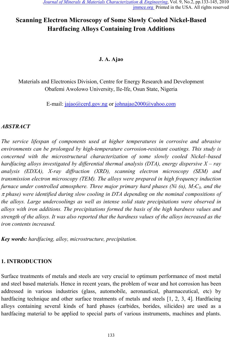 Journal of Minerals & Materials Characterization & Engineering, Vol. 9, No.2, pp.133-145, 2010 jmmce.org Printed in the USA. All rights reserved 133 Scanning Electron Microscopy of Some Slowly Cooled Nickel-Based Hardfacing Alloys Containing Iron Additions J. A. Ajao Materials and Electronics Division, Centre for Energy Research and Development Obafemi Awolowo University, Ile-Ife, Osun State, Nigeria E-mail: jajao@cerd.gov.ng or johnajao2000@yahoo.com ABSTRACT The service lifespan of components used at higher temperatures in corrosive and abrasive environments can be prolonged by high-temperature corrosion-resistant coatings. This study is concerned with the microstructural characterization of some slowly cooled Nickel–based hardfacing alloys investigated by differential thermal analysis (DTA), energy dispersive X – ray analysis (EDXA), X-ray diffraction (XRD), scanning electron microscopy (SEM) and transmission electron microscopy (TEM). The alloys were prepared in high frequency induction furnace under controlled atmosphere. Three major primary hard phases (Ni (α), M7C3, and the π phase) were identified during slow cooling in DTA depending on the nominal compositions of the alloys. Large undercoolings as well as intense solid state precipitations were observed in alloys with iron additions. The precipitations formed the basis of the high hardness values and strength of the alloys. It was also reported that the hardness values of the alloys increased as the iron contents increased. Key words: hardfacing, alloy, microstructure, precipitation. 1. INTRODUCTION Surface treatments of metals and steels are very crucial to optimum performance of most metal and steel based materials. Hence in recent years, the problem of wear and hot corrosion has been addressed in various industries (glass, automobile, aeronautical, pharmaceutical, etc) by hardfacing technique and other surface treatments of metals and steels [1, 2, 3, 4]. Hardfacing alloys containing several kinds of hard phases (carbides, borides, silicides) are used as a hardfacing material to be applied to special parts of various instruments, machines and plants.  134 J.A. Ajao Vol.9, No.2 These hard phases are made of chromium, tungsten and non-metallic elements (carbon, boron, silicon). Among these alloys with base nickel, cobalt or iron, nickel-based hardfacing alloys are often used because of their self-fluxing properties at high temperature [5, 6]. Nickel-based coatings are used in applications where wear resistance combined with oxidation or hot corrosion resistance is required. They are mainly used in chemical industry, petrol industry, glass mould industry, hot working punches, fan blades and mud purging elements in cement factories. Their advantages are especially related to coating large-sized components such as piston rods, earth– working machines etc. [7]. The presence of boride and carbide dispersions within their microstructures makes these nickel- based alloys exhibit excellent resistance to abrasive wear [8]. Furthermore, these hard coatings are widely employed to improve the quality of components whose surface is subjected to severe tribological conditions such as coal-fired boilers, heat exchangers, turbines, tools, extruders, plungers, rolls for rolling mills, agriculture machinery, etc. [1, 9]. In fact, as reported by Zhao et al [10], the NiCrBSi coating deposited by high-velocity oxy-fuel (HVOF) has excellent corrosion resistance because of the low porosity percentage, so that corrosive medium could not soak into the coating and the chemical composition changes in the surface layer do not cause the change in the whole coating. The corrosion of the NiCrBSi coating is not a selective one. Addition of chromium promotes the oxidation and corrosion resistance at elevated temperatures and increases the hardness of the coating by formation of hard phases. Boron depresses the melting temperature and contributes to the formation of hard phases. Silicon is added to increase the self- fluxing properties and lower the melting point of nickel, the base metal. However, it reduces the tensile strength of the alloy [11]. Carbon produces hard carbides with elevated hardness that promotes wear resistance of the coatings [10, 12]. The presence of carbon is also responsible for the formation of chromium carbides which are brittle, angular and hollow crystals that increase braze joint stress [13]. The good corrosion resistance of the alloy is assured by the presence of chromium while the wear resistance is directly connected to the relations between the matrix and the hard phases: nature (boride, silicide, carbide) distribution, form, dimensions and orientation relationship between the phases [14]. Due to various phases involved, the solidification paths of these alloys are particularly complex especially during slow cooling in differential thermal analysis (DTA). The microstructure of these alloys has not been deeply investigated [1, 8, 15] due to the complexity of their compositions and various complex phases involved which are particularly sensitive to different cooling conditions, hence the interest of the present work to undertake the microstructural studies of the phase transformations within the alloys with respect to their compositions and cooling conditions. The influence of the addition of iron (in various contents) on the microstructural changes of these alloys will also be investigated. 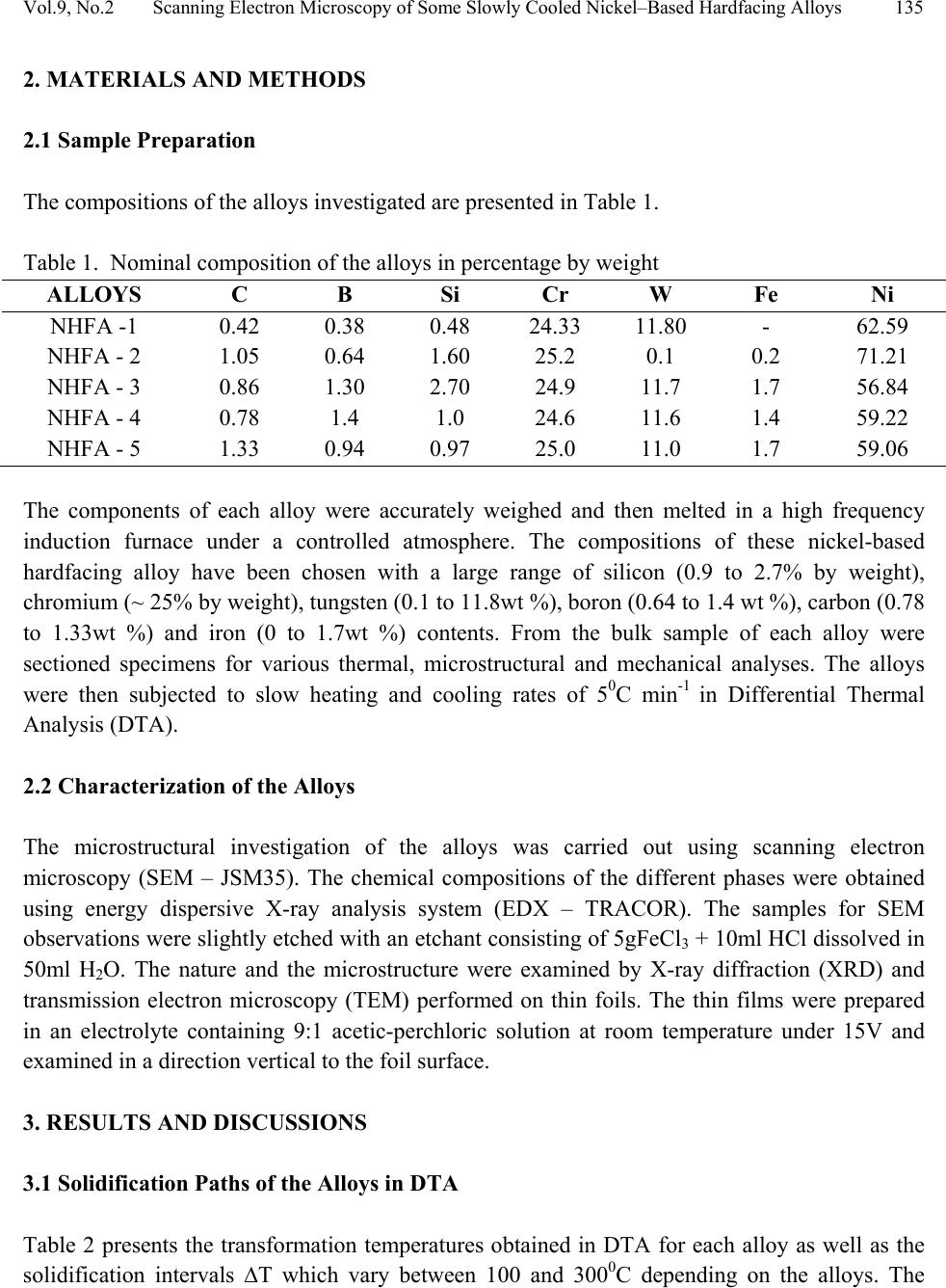 Vol.9, No.2 Scanning Electron Microscopy of Some Slowly Cooled Nickel–Based Hardfacing Alloys 135 2. MATERIALS AND METHODS 2.1 Sample Preparation The compositions of the alloys investigated are presented in Table 1. Table 1. Nominal composition of the alloys in percentage by weight ALLOYS C B Si Cr W Fe Ni NHFA -1 0.42 0.38 0.48 24.33 11.80 - 62.59 NHFA - 2 1.05 0.64 1.60 25.2 0.1 0.2 71.21 NHFA - 3 0.86 1.30 2.70 24.9 11.7 1.7 56.84 NHFA - 4 0.78 1.4 1.0 24.6 11.6 1.4 59.22 NHFA - 5 1.33 0.94 0.97 25.0 11.0 1.7 59.06 The components of each alloy were accurately weighed and then melted in a high frequency induction furnace under a controlled atmosphere. The compositions of these nickel-based hardfacing alloy have been chosen with a large range of silicon (0.9 to 2.7% by weight), chromium (~ 25% by weight), tungsten (0.1 to 11.8wt %), boron (0.64 to 1.4 wt %), carbon (0.78 to 1.33wt %) and iron (0 to 1.7wt %) contents. From the bulk sample of each alloy were sectioned specimens for various thermal, microstructural and mechanical analyses. The alloys were then subjected to slow heating and cooling rates of 50C min-1 in Differential Thermal Analysis (DTA). 2.2 Characterization of the Alloys The microstructural investigation of the alloys was carried out using scanning electron microscopy (SEM – JSM35). The chemical compositions of the different phases were obtained using energy dispersive X-ray analysis system (EDX – TRACOR). The samples for SEM observations were slightly etched with an etchant consisting of 5gFeCl3 + 10ml HCl dissolved in 50ml H2O. The nature and the microstructure were examined by X-ray diffraction (XRD) and transmission electron microscopy (TEM) performed on thin foils. The thin films were prepared in an electrolyte containing 9:1 acetic-perchloric solution at room temperature under 15V and examined in a direction vertical to the foil surface. 3. RESULTS AND DISCUSSIONS 3.1 Solidification Paths of the Alloys in DTA Table 2 presents the transformation temperatures obtained in DTA for each alloy as well as the solidification intervals ∆T which vary between 100 and 3000C depending on the alloys. The  136 J.A. Ajao Vol.9, No.2 DTA thermogrammes showed in general three to four peaks according to the nominal composition of the alloys. DTA samples were about 1.5g each. The interpretation of the thermal peaks obtained in DTA experiment was particularly difficult due to the complexity of the phase formations in the alloys as a result of the wide range of compositions of the different constituents of the alloys. Complementary microscope techniques were then employed to arrive at reasonable and scientific interpretations of the results. In fact the presence of heavy elements such as tungsten whose contrast in electron microscopy is similar to those of light elements such as boron or carbon did not facilitate this task. From the DTA experiments and the microstructural studies of the alloys three primary phases could be identified depending on the composition of the alloys. They are (i) the nickel solid solution containing silicon, a small amount of boron and chromium, iron, copper and tungsten; this nickel solid solution will be referred to as Ni (α) in order to distinguish it from pure nickel, (ii) the carbide of the type M7C3 where chromium is combined with the carbon wherein M represents chiefly chromium with small amount of tungsten, nickel, iron etc and also with a portion of the boron to form chromium boride, chiefly chromium boride MB type and (iii) the quaternary phase π largely rich in chromium, nickel, tungsten and silicon. Table 2. Transformation temperatures in 0C obtained in DTA and undercooling ∆T. The DTA experiments of alloy NHFA-1 show the presence of three peaks. The first peak formed at 13560C was due to the crystallization of the primary phase Ni (α) as shown in the micrograph of Fig. 1a. This reaction was followed by the formation of binary Ni (α)-Ni3B eutectic at 11700C and solid state transformation of Ni3B at 10650C. This type of transformation has been reported in a previous work [16]. The NHFA-2 alloy shows a typically dendritic microstructure (Fig. 1b). From DTA experiments, this alloy presents three peaks (Table 2). The highest transformation temperature at T1 = 1302.20C as shown in the DTA thermogramme of Fig. 2 corresponds to the solidification of the Ni(α) solid solution. ALLOY T1 T 2 T 3 T 4 ∆T NHFA-1 1356 1170 1065 - 291 NHFA-2 NHFA-3 1302 1230 1115 1185 1093 1065 - - 209 165 NHFA-4 1232 1176 998 - 234 NHFA-5 1295 1270 1140 1008 287  Vol.9, No.2 Scanning Electron Microscopy of Some Slowly Cooled Nickel–Based Hardfacing Alloys 137 Figure 1. (a) Scanning electron micrograph (SEM) of alloy NHFA-1 showing the primary phase of Ni (α) and the lamellar Ni (α)-Ni3B eutectic. (b) SEM of alloy NHFA-2 depicting the primary phase of Ni (α) with segregated precipitates within the matrix. Figure 2. A representative DTA thermogramme on alloy NHFA-2 showing three distinct transformation temperatures. 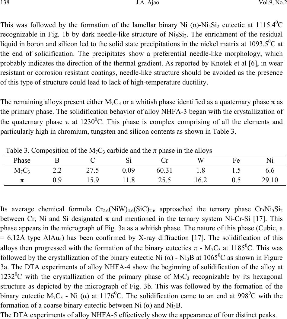 138 J.A. Ajao Vol.9, No.2 This was followed by the formation of the lamellar binary Ni (α)-Ni5Si2 eutectic at 1115.40C recognizable in Fig. 1b by dark needle-like structure of Ni5Si2. The enrichment of the residual liquid in boron and silicon led to the solid state precipitations in the nickel matrix at 1093.50C at the end of solidification. The precipitates show a preferential needle-like morphology, which probably indicates the direction of the thermal gradient. As reported by Knotek et al [6], in wear resistant or corrosion resistant coatings, needle-like structure should be avoided as the presence of this type of structure could lead to lack of high-temperature ductility. The remaining alloys present either M7C3 or a whitish phase identified as a quaternary phase π as the primary phase. The solidification behavior of alloy NHFA-3 began with the crystallization of the quaternary phase π at 12300C. This phase is complex comprising of all the elements and particularly high in chromium, tungsten and silicon contents as shown in Table 3. Table 3. Composition of the M7C3 carbide and the π phase in the alloys Phase B C Si Cr W Fe Ni M7C3 2.2 27.5 0.09 60.31 1.8 1.5 6.6 π 0.9 15.9 11.8 25.5 16.2 0.5 29.10 Its average chemical formula Cr2.6(NiW)4.6(SiC)2.6 approached the ternary phase Cr3Ni5Si2 between Cr, Ni and Si designated π and mentioned in the ternary system Ni-Cr-Si [17]. This phase appears in the micrograph of Fig. 3a as a whitish phase. The nature of this phase (Cubic, a = 6.12Å type AlAu4) has been confirmed by X-ray diffraction [17]. The solidification of this alloys then progressed with the formation of the binary eutectics π - M7C3 at 11850C. This was followed by the crystallization of the binary eutectic Ni (α) - Ni3B at 10650C as shown in Figure 3a. The DTA experiments of alloy NHFA-4 show the beginning of solidification of the alloy at 12320C with the crystallization of the primary phase of M7C3 recognizable by its hexagonal structure as depicted by the micrograph of Fig. 3b. This was followed by the formation of the binary eutectic M7C3 - Ni (α) at 11760C. The solidification came to an end at 9980C with the formation of a coarse binary eutectic between Ni (α) and Ni3B. The DTA experiments of alloy NHFA-5 effectively show the appearance of four distinct peaks. 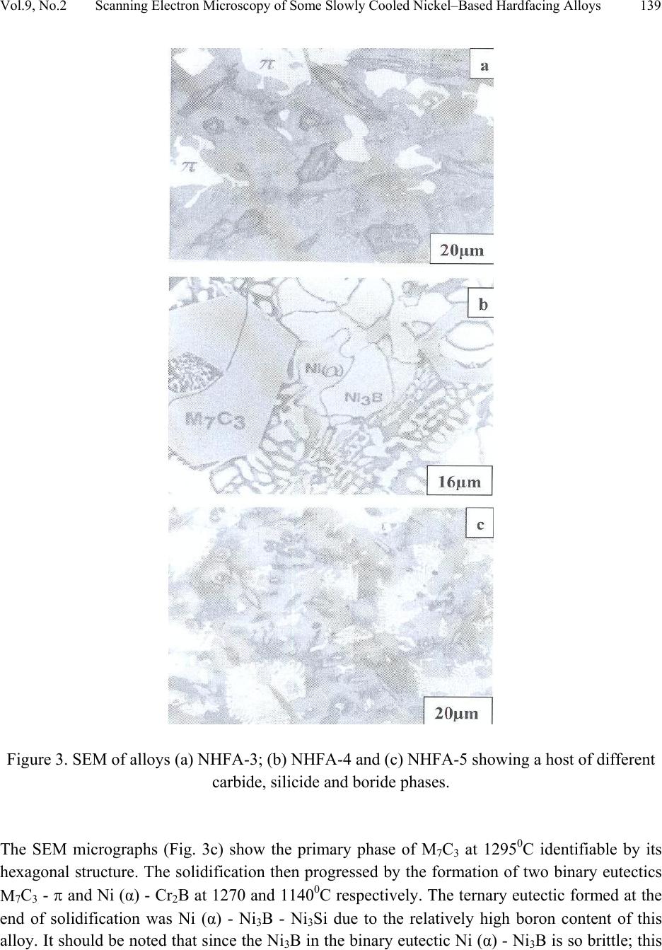 Vol.9, No.2 Scanning Electron Microscopy of Some Slowly Cooled Nickel–Based Hardfacing Alloys 139 Figure 3. SEM of alloys (a) NHFA-3; (b) NHFA-4 and (c) NHFA-5 showing a host of different carbide, silicide and boride phases. The SEM micrographs (Fig. 3c) show the primary phase of M7C3 at 12950C identifiable by its hexagonal structure. The solidification then progressed by the formation of two binary eutectics M7C3 - π and Ni (α) - Cr2B at 1270 and 11400C respectively. The ternary eutectic formed at the end of solidification was Ni (α) - Ni3B - Ni3Si due to the relatively high boron content of this alloy. It should be noted that since the Ni3B in the binary eutectic Ni (α) - Ni3B is so brittle; this  140 J.A. Ajao Vol.9, No.2 binary eutectic structure is least tough and ductile in the matrix. This could give rise to the formation of cracks or fissures in the hardfacing layer of the alloy under certain conditions of employment. Hence the presence of Ni3B in these alloys needs to be highly monitored and regulated. It was, however, observed that the presence of the ternary eutectic Ni (α) - Ni3B - Ni3Si is an asset in these alloys because the Ni3Si which is less hard (having a Vickers hardness of 800 to 850) but more tough and ductile than Ni3B interrupts the envelope of the Ni (α) by the Ni3B in the binary Ni (α) - Ni3B lamellar eutectic, hence reducing the damaging effect of this eutectic. This is because corrosion first sets in and develops along paths formed by pores, microcracks and lamellar structure resulting in exfoliation or laminar peeling – off of coatings. From Table 1, these alloys contain iron in various amounts from 0 to 1.8% by weight. From Table 2, it is observed that all the alloys passed through a large amount of undercooling in DTA experiments. The least amount of undercooling (∆T = 1650C) was observed in alloy NHFA-3 containing the largest amounts of boron, silicon and iron while the largest amount of undercooling (∆T = 2910C) was recorded in alloy NHFA-1 containing no iron addition. Hence it could be safely said that the presence of iron in these alloys played a crucial role in degree of undercooling of these alloys. This could be the basis of various forms of solid-state precipitations observed in these types of alloys with iron additions. 3.2 Precipitations in the Ni (α) Solid Solution Large segregations of silicon in the form of the silicide β Ni3Si were observed along the edges of the Ni (α) solid solution (Fig.1b). The slow cooling rate gave rise to reversible process for forming thermodynamically stable phases. The diffusion coefficients of the element diffusing in the Ni (α) may be expressed as: D = D0exp[-Q/kT] where Q = activation energy in Cal.mol-1 T = temperature in K According to Adda and Philibert [18], DSi = 1.5exp[-61700/kT] between 1100 and 13000C. Hence, from the above relations, the diffusion coefficient of silicon (DSi) in nickel could be estimated as 1.48 x 10⁻⁹cm2.s-1. The precipitates observed in the alloys (except NHFA-1 alloy) were as a result of large segregations of silicon in the Ni (α) phase. This could be explained by the solute exchange of silicon between the Ni (α) and the remaining liquid during cooling. This resulted in the concentration profile of silicon being slightly higher in the Ni (α) solid solution as shown in the micrograph of Fig. 1b. Similar observations have been reported in the nickel-rich Ni-Si binary alloys [19]. Detailed microstructural observations showed that these precipitates exhibited two characteristic morphologies (cuboids and spheroids) coherent with the Ni (α) matrix as depicted in the micrograph of Fig. 4a. These morphologies have been explained by Ricks et al [20] by the sign of the lattice misfit between the matrix and the precipitates and the supersaturation of the diffusing species. Lebaili et al [15] reported the evolution of the cuboid  Vol.9, No.2 Scanning Electron Microscopy of Some Slowly Cooled Nickel–Based Hardfacing Alloys 141 precipitates into spherical precipitation and explained this by the growth of β Ni3Si along preferential planes. This is in good agreement with the observations in this work. In fact the occurrence of this type of precipitation has been extensively investigated in the case of γ (Ni3Al) precipitates in the nickel matrix as it constitutes the strengthening mode for super alloys [20]. The presence of these precipitates has also enhanced the mechanical properties of these alloys as evidenced by the dislocation loops around the precipitates (Fig. 4b) in the alloys under investigation thereby increasing the strength of the alloys. Figure 4. (a) Transmission electron micrographs (TEM) showing the cuboid and spheroid precipitates within the Ni(α) matrix and (b) dislocations loops around the precipitates. Other secondary boride precipitation observed in the nickel matrix made this matrix to be particularly interesting to study (Figure 1b). From qualitative analysis, it was observed that these needle-like precipitates within the volume of Ni (α) matrix were rich in boron, chromium and tungsten. They are the boride of the type Cr2B. In fact from the nominal composition of this  142 J.A. Ajao Vol.9, No.2 alloy, carbon, boron and tungsten are rather not in appreciable quantities; hence they segregated within the Ni (α) matrix. There was no evidence of the presence of chromium boride with higher boron content such as CrB in all the alloys under investigation. During cooling, the solidification of the M7C3 and MB phases from the liquid alloys occurred at sufficiently higher temperatures (12700C to 12300C) than the temperature range in which the matrix components solidified (9980C to 11400C). For most of the matrix components, the M7C3 and MB crystallized as the primary and secondary phases so as to be dispersed in the matrix before the solidifying temperatures of the matrix components were reached. Since the M7C3 and MB are both hard, their nature, distribution, form, dimensions and crystallographic orientation relationship (mutual or otherwise) are responsible for the wear resistance property of the alloys. It should be noted that the degree of undercooling in these alloys was considerably reduced compared to Ni-B binary [16] and Ni-B-Si ternary [21] alloys. This could be associated with the presence of chromium which increased the liquidus temperature of the alloys. 3.3 Hardness of the alloys The hardness values of the alloy are presented in Table 4. Table 4. Average hardness values of the alloys under investigation. Alloy HV10 NHFA-1 290 NHFA-2 335 NHFA-3 430 NHFA-4 415 NHFA-5 455 A plot of the hardness values of the alloys as a function of the iron contents is shown in Fig. 5. From the figure, it can be seen that the hardness values increased as the iron contents increased. Alloys NHFA-3 and NHFA-4 have close hardness values. This is probably due to the high tungsten, boron and silicon contents in the alloys.  Vol.9, No.2 Scanning Electron Microscopy of Some Slowly Cooled Nickel–Based Hardfacing Alloys 143 -0,20,0 0,2 0,4 0,60,8 1,0 1,2 1,4 1,6 1,8 280 300 320 340 360 380 400 420 440 460 HV Iron contents wt% Figure 5. Average hardness values of the alloys as a function of the iron contents. On the other hand, alloy NHFA-1 has relatively low boron and silicon contents thereby presenting low hardness value. The wide gap between the hardness values of alloys NHFA-2 and NHFA-5 could be attributed to the low iron and tungsten contents in alloy NHFA-2. The high hardness value of NHFA-5 could be associated with the high concentration of the hard carbide, silicide and boride phases within the matrix due to the high contents of all the metallic and non- metallic additions. 4. CONCLUSIONS • The morphology of some nickel-based hardfacing alloys has been studied by differential thermal analysis (DTA), energy dispersive X-ray analysis (EDXA), X-ray diffraction (XRD), scanning electron microscopy (SEM) and transmission electron microscopy (TEM). • Three major primary phases (Ni (α), M7C3, and the π phase) were observed during slow cooling in DTA depending on the nominal compositions of the alloys. Intense segregations of the silicide phase Ni3Si were observed in the nickel matrix. • Large undercoolings in addition to intense solid state precipitations were observed in alloys with iron additions. The precipitates are responsible for the high hardness values and strength of the alloys. • The hardness values of the alloys were found to increase as the iron contents increased.  144 J.A. Ajao Vol.9, No.2 ACKNOWLEDGEMENTS The author is indebted to Dr. Marianna Kemell for assistance in electron microscopy and to Centre for Energy Research and Development, Obafemi Awolowo University, Ile-Ife, Nigeria for granting him leave of absence during the preparation of this work. REFERENCES [1] Lugscheider, E., Knotek, O. and Klohn, K., 1978, “Development of Ni-Cr-Si base Filler Metals”, J. Weld. Res. Supp., Vol. 57 pp. 319 - 325. [2] Gonz´alez, R., Cadenas, M., Fern´andez, R., Cortizo, J. L. and Rodr´ıguez, E., 2007, “Wear behaviour of flame sprayed NiCrBSi coating remelted by flame or by laser”, Wear Vol. 262 pp. 301–307. [3] Knotek, O. and Lugscheider, E., 1976, “Brazing Filler Metals based on Reacting Ni-Cr-B-Si Alloys”, Welding Research Supplement pp. 314 – 318. [4] Steffens, H.D., Ferrari, F., Sturlese, S.,and Pawlowski, L., 1992, “Fundamentals of Thermal Spraying Technology”, Mats. Eng., Vol. 3(2) pp. 183 - 190 [5] Knotek, O., Reimann, H. and Lohage, P., 1981, “Reactions between Ni-Cr-B-Si matrixes and carbide additives in coating during fusion treatment”, Thin Solid Films Vol. 83 pp. 361 – 367. [6] Knotek, O., Lugscheider, E. and Wichert, W., 1978, “On the structure and properties of wear and corrosion resistant Ni-Cr-W-C-Si Alloys”, Thin Solid Films Vol. 53 pp. 303 – 312. [7] Rosso, M and Bennani, A., 1998, “Studies of new applications of Ni-based powders for hardfacing processes”, PM World Congress Thermal Spraying/Spray Forming, pp. 524-530. [8] Knotek, O., Lugscheider, E. and Reimann, H., 1975, “Structure of Ni-rich Ni-Cr-B-Si Coating Alloys”, J. Vac. Sci. Technol. Vol. 12(4) pp. 770 - 772. [9] Gonz´alez, R., Garc´ıa, M. A., Pe˜nuelas, I., Cadenas, Roc´ıo, Fern´andez, Ma. Del., Hern´andez Battez, A., Felgueroso, D., 2007, “Microstructural study of NiCrBSi coatings obtained by different processes”, Wear Vol. 263 pp. 619–624. [10] Zhao, W-M., Wang, Y., Han, T., Wu K-Y. and Xue, J., 2005, “Corrosion mechanism of NiCrBSi coatings deposited by HVOF”, Surf. Coat. Technol. Vol. 190 pp. 293 – 298 [11] Sidhu, T. S., Prakash, S. and Agrawal, R. D., 2006, “Hot corrosion and performance of Nickel - based coatings”, Current Science Vol. 90(1) pp. 41 – 47. [12] Otsubo, F., Era, H. and Kishitake, K., 2000, “Structure and phases in Nickel-base self- fluxing alloy coating containing high chromium and boron”, J. Ther. Spray Technol. Vol. 9 pp. 107 – 113 [13] Lee, C. H. and Min, K. O., 2000, “Effects of heat treatment on the microstructure and properties of HVOF – sprayed Ni – Cr – W – Mo – B alloy coatings”, Surf. Coat. Technol. Vol. 132 pp. 49 – 57  Vol.9, No.2 Scanning Electron Microscopy of Some Slowly Cooled Nickel–Based Hardfacing Alloys 145 [14] Wang, B. Q. and Luer, K., 1994, “The erosion – oxidation behaviour of HVOF Cr3C2 – NiCr cermet coating”, Wear Vol. 174 pp. 177 – 185. [15] Lebaili, S., Durand-Charre, M. and Hamar-Thibault, S., 1988, “The Metallurgical Structure of as – solidified Ni-Cr-B-Si-C Hardfacing Alloys”, J. Mat. Sci. Vol. 23 pp. 3603 – 3611 [16] Ajao, J. and Hamar-Thibault, S., 1988, “Influence of Additions on the Solidification Behaviour of Ni-B Alloys- Crystallography of the Ni - Ni3B eutectic”, J. of Mat. Sci. Vol. 23, pp. 1112-1125. [17] Gladyshevski, E. I. and Borusevich L. K., 1963, “Ternary system of Cr-Ni-Si”. Zh. Neorgan. Khim, Vol. 8 pp. 1915-1918 [18] Adda, Y. and Philibert J. La diffusion dans les solides, Presses Universitaires de France, 1966. [19] Lebaili, S. and Hamar-Thibault, S., 1984, “Solid State Transformations During Cooling in the Ni-rich Portion of the Ni-Si system”, Z. Metallkde Vol. 75 pp. 764-770. [20] Ricks, R. A., Porter A. J. and Ecob R. C., 1983, “The growth of γ precipitates in nickel- based superalloys”. Acta Metall., Vol. 31, pp. 43-53. [21] Lebaili, S. and Hamar-Thibault, S., 1984, “Equilibres Liquide-solide dans le system Ni-B-Si dans la region riche en nickel”, Acta Metall. Vol. 35(3) pp. 701-710. |