 J. Biomedical Science and Engineering, 2012, 5, 360-368 JBiSE http://dx.doi.org/10.4236/jbise.2012.57046 Published Online July 2012 (http://www.SciRP.org/journal/jbise/) Molecular network using molecular circuit for drug delivery use Narongchai Moongfangklang1, Somsak Mitatha2, Surasak Pipatsart3, Preecha P. Yupapin3 1School of Information Technology, Payao University, Payao, Thailand 2Hybrid Computing Research Laboratory, Faculty of Engineering, King Mongkut’s Institute of Technology Ladkrabang, Bangkok, Thailand 3Nanoscale Science and Engineering Research Alliance (N’SERA), Faculty of Science, King Mongkut’s Institute of Technology Ladkrabang, Bangkok, Thailand Email: kypreech@kmitl.ac.th Received 5 August 2011; revised 9 October 2011; accepted 27 April 2012 ABSTRACT A novel design of molecular networks for drug deliv- ery application using a PANDA ring resonator is proposed. By using the intense optical vortices gener- ated within the PANDA ring resonator, the required molecules can be trapped and moved (transported) dynamically within the wavelength router and bus networks, in which the required drug delivery can perform within the wavelength router before reach- ing the required destination. PANDA ring is a modi- fied optical add/drop filter. It is a name of Chinese bear, which is used to name the device by the authors. The advantage of the proposed system is that the drug delivery networks can perform within the tiny system (thin film device), where the large molecular drug networks such as ring, star and bus networks are also proposed, in which the applications such as Alzheimers’ and Parkinson diagnosis, blood circula- tion networks and in situ surgery operation are dis- cussed. Keywords: Molecular Networks; Blood Circulation Network; Drug Networks; Neural System and Network 1. INTRODUCTION Since over 20 years ago, optical traps have emerged as a powerful tool with broad-reaching applications in biol- ogy and physics. Optical tweezers have been applied widely in many research areas such as biology, medicine, engineering and physics [1]. Optical trapping techniques provide unique means to manipulate biological particles, biological cells such as virus, living cells and subcellular organelles, without nondestructive manipulating mole- cules, since this technique was the first invented by Ash- kin et al. [2] and his colleagues used it to trap viruses and bacteria, although the bacteria were killed by the high energy of the laser. With the application of a less dam- aging infrared (IR) laser, it is now possible to trap and manipulate a single yeast, bacterium and organelle with- out damage [3]. In specific to medicine and the applica- tion of nanotechnology, which is the field of interest, obviously experiment of a single red blood cell (RBC) deformability test is performed by using optical trapping plastic in microfluidic chip was clearly demonstrated ex- periment by Lee et al. [4,5] and lab-on-a-chip for RBCs transportation in the capillary network to circulate oxy- gen and carbon dioxide throughout the human body [6]. For the optical trapping manipulation molecules in liquid core wave guide and application to drug delivery has reported by Suwanpayak et al. [7] in a PANDA ring resonator is used to form, transmit and receive the mi- croscopic volume (drug) by controlling the ring parame- ters. The microscopic volume can be trapped and moved (transported) dynamically within the wavelength router or network. Optical buffer is recognized as an essential component in a wavelength router, in which the packets of data can be storaged for resolving packet contention problem and also delay the outgoing packets [8,9]. In practice, the optical router patents have been proposed and recorded [10-12], which can be useful for various applications. Recently, the promising techniques of microscopic vol- ume trapping and transportation within the add/drop multiplexer have been reported in both theory [13] and experiment [14], respectively, in which the transporter is known as an optical tweezer. Here, the optical tweezer generation technique has become a powerful tool for manipulation of micrometer-sized particles. To date, the useful static tweezers are well recognized and realized. Moreover, the use of dynamic tweezers is now also real- ized in practical works [15-17]. Schulz et al. [18] have shown that the transfer of trapped atoms between two optical potentials could be performed. In principle, an OPEN ACCESS  N. Moongfangklang et al. / J. Biomedical Science and Engineering 5 (2012) 360-368 361 optical tweezers use forces exerted by intensity gradients in the strongly focused beams of light to trap and move the microscopic volumes of matters, in which the other combination of force is induced by the interaction be- tween photons, which is caused by the photon scattering effects. In application, the field intensity can be adjusted and tuned, in which the desired gradient field and scat- tering force can form the suitable trapping force. Hence, the appropriated force can be configured for the trans- mitter/receiver part, which can perform the long distance microscopic transportation. In this paper, the dynamic optical tweezers/vortices are generated using a dark soliton, bright soliton and Gaus- sian pulse propagating within an add/drop optical multi- plexer incorporating two nanoring resonators (PANDA ring resonator). The dynamic behaviors of solitons and Gaussian pulses are well described in reference [19]. By using the proposed system, the transceiver can be inte- grated and performed by using a single device. Here, the use of the molecular buffers and bus networks to form the drug volume transportation, especially, for large drug volumes delivery and transportation, which can be available for molecular diagnosis and networks, blood circulation networks, Alzheimer’s and Parkinson’s diag- nosis. 2. PRINCIPLES AND METHODS In operation, the trapping forces are exerted by the inten- sity gradients in the strongly focused beams of light to trap and move the microscopic volumes of matters, in which the optical forces are customarily defined by the relationship [18] m Qn P Fc (1) where Q is a dimensionless efficiency, nm is the index of refraction of the suspending medium, c is the speed of light, and P is the incident laser power, measured at the specimen. Q represents the fraction of power utilized to exert force. For plane waves incident on a perfectly ab- sorbing particle, Q is equal to 1. To achieve stable trap- ping, the radiation pressure must create a stable, three- dimensional equilibrium. Because biological specimens are usually contained in aqueous medium, the depend- ence of F on nm can rarely be exploited to achieve higher trapping forces. Increasing the laser power is possible, but only over a limited range due to the possibility of optical damage. Q itself is therefore the main determi- nant of trapping force. It depends upon the NA (numeri- cal aperture), laser wavelength, light polarization state, laser mode structure, relative index of refraction, and geometry of the particle. Furthermore, in the Rayleigh regime, trapping forces decompose naturally into two components. Since, in this limit, the electromagnetic field is uniform across the di- electric, particles can be treated as induced point dipoles. The scattering force is given by scatt , m S Fn c (2) where 2 2 42 2 8 π 32 m kr rm 1 (3) is the scattering cross section of a Rayleigh sphere with radius r. S is the time averaged Poynting vector, n is the index of refraction of the particle, m mnn is the rela- tive index, and 2πm kn is the wave number of the light. Scattering force is proportional to the energy flux and points along the direction of propagation of the inci- dent light. The gradient field (Fgrad) is the Lorentz force acting on the dipole induced by the light field. It is given by 2 grad , 2 E (4) where 2 23 2 1 2 mm nr m (5) is the polarizability of the particle. The gradient force is proportional and parallel to the gradient in energy den- sity (for m > 1). The large gradient force is formed by the large depth of the laser beam, in which the stable trap- ping requires that the gradient force in the direction, which is against the direction of incident light (dark soli- ton valley), and it is greater than the scattering force. By increasing the NA, when the focal spot size is decreased, the gradient strength is increased [19,20], which can be formed within the tiny system, for instance, nanoscale device (nanoring resonator). ˆ z In our proposal, the trapping force is formed by using a dark soliton, in which the valley of the dark soliton is generated and controlled within the PANDA ring reso- nator by the control port signals. From Figure 1, the out- put field (Et1) at the through port is given by [19] 22 112 23 22 22 12 2 22 , 1 n nn n LL jk tii LL LL jk jk ii LL jk EAEBEe CE eDEe Ee (6) where Copyright © 2012 SciRes. OPEN ACCESS  N. Moongfangklang et al. / J. Biomedical Science and Engineering 5 (2012) 360-368 Copyright © 2012 SciRes. 362 The power output () at through port is written as 1t P Connecting router 2 11 . tt PE (7) The output field (Et2) at drop port is expressed as [19] (see Eq.8) Where 2112 111 1X2 , 121 1111Y2 The power output () at drop port is 2t P 2 22 . tt PE (9) In operation, the optical tweezers can be trapped, transported and stored within the PANDA ring resonator and wavelength router, which can be used to form the microscopic volume (molecule) transportation, drug de- livery via the waveguide [14], in which the manipulation of trapped microscopic volumes within the optical twee- zers has been reported. (a) (b) Figure 1. Schematic diagram of a buffer and bus networks, where (a) a PANDA ring resonator, (b) a wavelength router and bus networks, where Radd is the add/drop filter radius, RR and RL are the right and left ring resonator radii, respectively. 3. DRUG DELIVERY NETWORKS 12 11A , OPEN ACCESS 1212 111 0 B E , 11 2200 11 C EE, 2 1211220 111 10 D EE and 12120 1111 0 E EE . Molecular buffer is a device that can be used to store or delay atoms/molecules for a period of time (see Figure 2), where light intensity and velocity can also be con- trolled, which was described by the authors in references [21,22], which is available for medical application. Mo- lecular buffer is the new device, which is operated in the same way as gases buffer [23]. The polarizibility of the particle is calculated by using an Eq.5, in this case, we assume that the sphere particle is polystyrene (n = 1.5894) and the liquid medium is water (n = 1.33), and the optical power which is required to trap particles of a certain size/polarizibility is 9.1 W, which is the slope as shown in Figure 3(a). In simulation, the bright soliton with cen- ter wavelength at 1.50 µm, peak power 2 W, pulse 35 fs is input into the system via the input port, the coupling coefficients are given as 0 = 0.5, 1 = 0.35, 2 = 0.1 and 3 = 0.35, respectively. The ring radii are Radd = 100 µm, R Here Et and Ed represent the optical fields of the through port and drop ports, respectively. = kneff is the propagation constant, neff is the effective refractive index of the waveguide, and the circumference of the ring is L = 2R, where R is the radius of the ring. 1 and 2 are the coupling coefficients of the add/drop filters, kn = 2/ is the wave propagation number for in a vacuum, and the waveguide (ring resonator) loss is = 0.5 dB·mm−1. The fractional coupler intensity loss is = 0.1. In the case of the add/drop device, the nonlinear refractive index is not effect to the system, therefore, it is neglected. The elec- tric fields 0 and 0 E E are the field circulated within the nanoring at the right and left side of add/drop optical filter. R = RL = 40 µm, respectively. To date, the evidence of the practical device with the radius of 2 - 3 µm has been reported by the authors in reference [24]. Aeff are 0.50, 0.25 and 0.25 m2: In this case, the dynamic tweezers (gradient fields) can be in the forms of bright solitons, Gaussian pulses and dark solitons, which can be used to 2 22 22 121201 002 2222 2 22 00 11 11 1 nn n LL LL jk jk iLi ti LL jk L EEeXEE Ee EE YE Ee , (8) 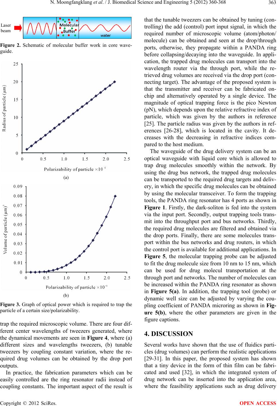 N. Moongfangklang et al. / J. Biomedical Science and Engineering 5 (2012) 360-368 363 Laser eam Figure 2. Schematic of molecular buffer work in core wave- guide. (a) (b) Figure 3. Graph of optical power which is required to trap the particle of a certain size/polarizability. trap the required microscopic volume. There are four dif- ferent center wavelengths of tweezers generated, where the dynamical movements are seen in Figure 4, where (a) different sizes and wavelengths tweezers, (b) tunable tweezers by coupling constant variation, where the re- quired drug volumes can be obtained by the drop port outputs. In practice, the fabrication parameters which can be easily controlled are the ring resonator radii instead of coupling constants. The important aspect of the result is that the tunable tweezers can be obtained by tuning (con- trolling) the add (control) port input signal, in which the required number of microscopic volume (atom/photon/ molecule) can be obtained and seen at the drop/through ports, otherwise, they propagate within a PANDA ring before collapsing/decaying into the waveguide. In appli- cation, the trapped drug molecules can transport into the wavelength router via the through port, while the re- trieved drug volumes are received via the drop port (con- necting target). The advantage of the proposed system is that the transmitter and receiver can be fabricated on- chip and alternatively operated by a single device. The magnitude of optical trapping force is the pico Newton (pN), which depends upon the relative refractive index of particle, which was given by the authors in reference [25]. The particle radius was given by the authors in ref- erences [26-28], which is located in the cavity. It de- creases with the decreasing in refractive indices com- pared to the host medium. The waveguide of the drug delivery system can be an optical waveguide with liquid core which is allowed to trap drug molecules smoothly within the network. By using the drug bus network, the trapped drug molecules can be transported to the required drug targets and deliv- ery, in which the specific drug molecules can be obtained by using the molecular transceiver. To form the trapping tools, the PANDA ring resonator has 4 ports as shown in Figure 1. Firstly, the dark-soliton is fed into the system via the input port. Secondly, output trapping tools trans- mit into the throughput port and bus networks. Thirdly, the required drug molecules are filtered and obtained via the drop ports. Finally, there are some molecules trans- port within the bus networks and drug routers, in which the control port is available for additional applications. In Figure 5, the molecular trapping probe can be adjusted to fit the drug molecule size from 10 nm to 15 nm, which can be used for drug molecul transportation at the through port and networks. The number of molecules can be increased within the PANDA ring resonator as shown in Figure 5(a). In addition, the trapping tool (probe) or dynamic well size can be adjusted by varying the cou- pling coefficient of PANDA microring as shown in Fig- ure 5(b), where the other parameters are given in the figure captions. 4. DISCUSSION Several works have shown that the use of fluidics parti- cles (drug volumes) can perform the realistic applications [29-31]. In this paper, the proposed system has shown that a tiny device in the form of thin film can be fabri- cated and used [32], in which the integrated system of drug network can be inserted into the application area, where the feasibility applications such as drug delivery Copyright © 2012 SciRes. OPEN ACCESS 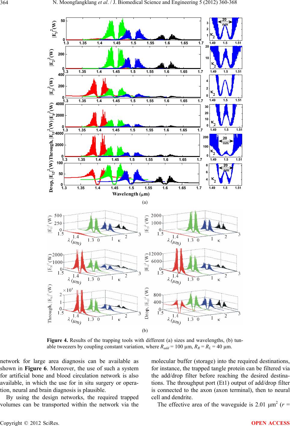 N. Moongfangklang et al. / J. Biomedical Science and Engineering 5 (2012) 360-368 364 1.3 1.351.41.45 1.51.55 1.61.65 1.7 0 2000 4000 Through, |E t1 | 2 (W) 1.3 1.35 1.41.45 1.51.55 1.6 1.65 1.7 0 50 100 Drop, |E t2 | 2 (W) W avelength ( m) 1.3 1.35 1.41.45 1.51.55 1.61.65 1.7 0 50 |E 1 | 2 (W) 1.3 1.35 1.41.45 1.51.55 1.61.65 1.7 0 200 |E 2 | 2 (W) 1.3 1.35 1.41.45 1.51.55 1.61.65 1.7 0 200 400 |E 3 | 2 (W) 1.3 1.35 1.41.45 1.51.55 1.61.65 1.7 0 2000 4000 |E 4 | 2 (W) 1.49 1.51.51 1 2 3 1.49 1.5 1.51 10 20 1.49 1.5 1.51 0 2 4 1.49 1.5 1.51 0 10 20 30 1.49 1.5 1.51 4 6 8 1.49 1.51.51 0 100 200 20 nm 20 nm 20 nm (a) (b) Figure 4. Results of the trapping tools with different (a) sizes and wavelengths, (b) tun- able tweezers by coupling constant variation, where Radd = 100 µm, RR = RL = 40 µm. network for large area diagnosis can be available as shown in Figure 6. Moreover, the use of such a system for artificial bone and blood circulation network is also available, in which the use for in situ surgery or opera- tion, neural and brain diagnosis is plausible. By using the design networks, the required trapped volumes can be transported within the network via the molecular buffer (storage) into the required destinations, for instance, the trapped tangle protein can be filtered via the add/drop filter before reaching the desired destina- tions. The throughput port (Et1) output of add/drop filter is connected to the axon (axon terminal), then to neural cell and dendrite. The effective area of the waveguide is 2.01 μm2 (r = Copyright © 2012 SciRes. OPEN ACCESS  N. Moongfangklang et al. / J. Biomedical Science and Engineering 5 (2012) 360-368 365 1.3 1.35 1.4 1.451.5 1.551.6 1.65 1.7 0 1000 2000 Through, |E t1 | 2 (mW) 1.3 1.35 1.4 1.45 1.5 1.551.6 1.65 1.7 0 20 40 60 80 Wavelength ( m) Drop, |E t2 | 2 (mW) 1.3 1.35 1.4 1.45 1.5 1.551.6 1.65 1.7 0 20 40 |E 1 | 2 (mW) 1.31.35 1.41.45 1.51.55 1.61.651.7 0 100 200 |E 2 | 2 (mW) 1.3 1.35 1.4 1.45 1.5 1.55 1.6 1.65 1.7 0 100 200 |E 3 | 2 (mW) 1.31.35 1.4 1.45 1.51.55 1.61.651.7 0 1000 2000 |E 4 | 2 (mW) 1.44 1.4451.45 1.455 1.46 0.5 1 1.5 2 2.5 1.44 1.445 1.45 1.455 1.46 2 4 6 8 10 12 1.44 1.445 1.45 1.455 1.46 0 5 10 1.441.445 1.45 1.455 1.46 0 50 100 1.44 1.445 1.45 1.455 1.46 0 20 40 60 80 100 1.44 1.445 1.45 1.455 1.46 2 3 4 5 6 Wave le n gt h ( m) 15 nm 15 nm 10 nm 10 nm 15 nm 10 nm (a) (b) Figure 5. Result of the dynamic tweezers with different (a) wavelengths and (b) coupling constants, where Radd = 15 µm, RR = RL = 3 µm. 800 nm) and the outside diameter of the microtubule is 25 nm [33]. The size of axons diameter at birth is 1 μm, it increases through childhood (7 years) to 12 μm and later to 24 μm at adulthood [34]. In case of Alzheimer’s diagnosis as shown in Figure 6(b), the optical tool is connected the axon and between the nerve cells, which can be used to trap the tangle protein into the removal storage by add/drop filter (control port), otherwise, the Copyright © 2012 SciRes. OPEN ACCESS 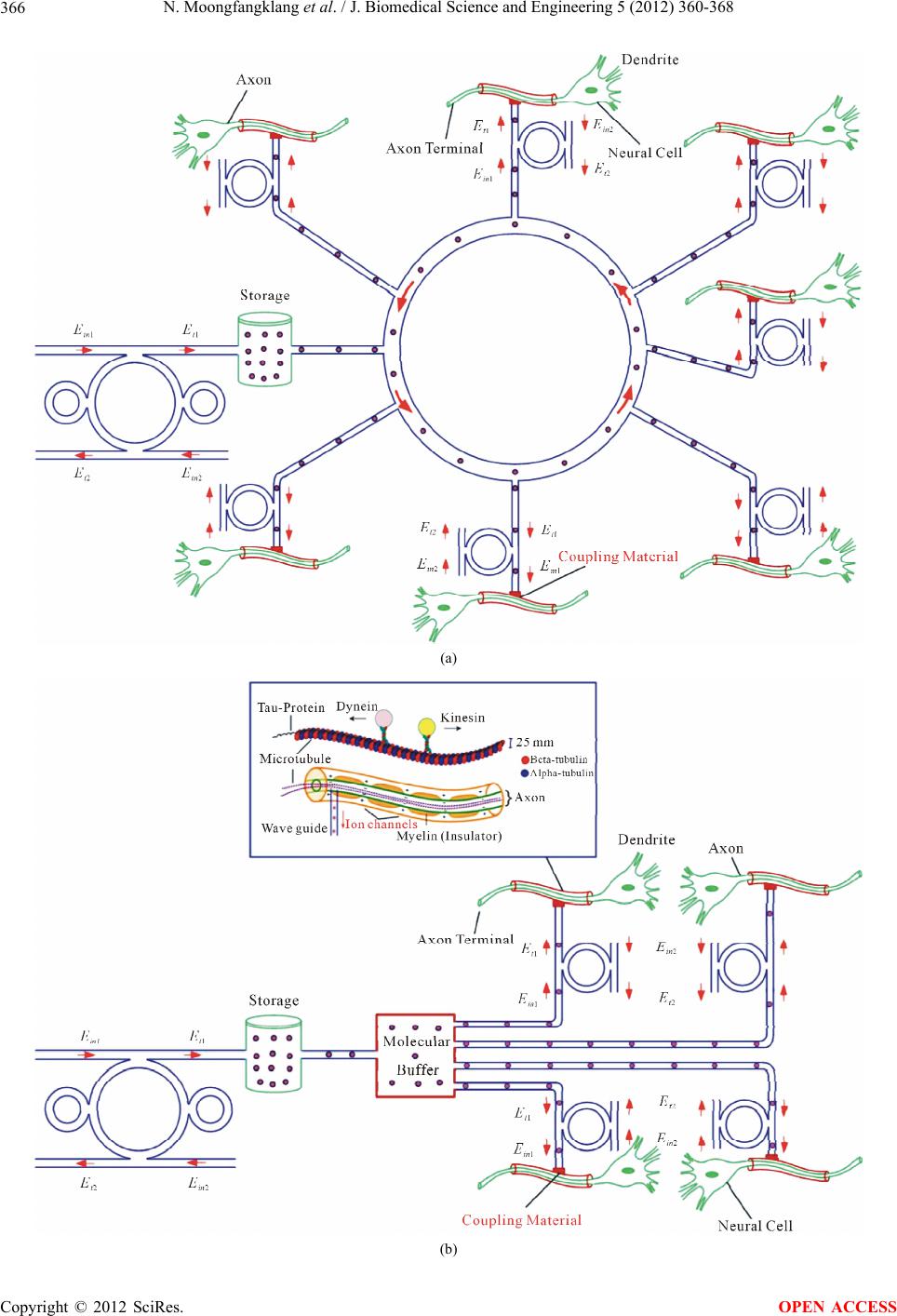 N. Moongfangklang et al. / J. Biomedical Science and Engineering 5 (2012) 360-368 366 (a) (b) Copyright © 2012 SciRes. OPEN ACCESS  N. Moongfangklang et al. / J. Biomedical Science and Engineering 5 (2012) 360-368 367 (c) Figure 6. Schematic diagram of molecular networks, where (a) a ring network; (b) a star network; and (c) a bus network. bus network as design can be used to trap the molecular motor to activate the information of neuronal cell at the same time. For better access, the coupling material is required to use as waveguide-axon coupling. 5. CONCLUSIONS We have proposed the interesting system that can be used form the molecular networks to trap (delay) and transport molecules into the liquid core waveguide and networks by using the optical tweezers, which can be used to form the drug storage and delivery system. Such a system can be available for molecular drug targeting and diagnosis. By utilizing the reasonable dark soliton input power, the dynamic tweezers can be controlled and stored (delayed) within the system before reaching the final destination. In conclusion, we have shown that the use of a mo- lecular networks to form the long distance drug molecule transportation being realized by using the proposed sys- tem, in which the drug delivery or molecular communi- cation can be performed via the wavelength router to the required (connecting) targets, which can be available for large network system (neural system) in the near future. REFERENCES [1] Lu, S.J., Qiang F., Park, J.S., Vida, L., Lee, B.S., Straus- bauch, M., Wettstein, P.J., Honig, G.R. and Lanza, R. (2008) Biological properties and enucleation of red blood cells from human embryonic stem cells. Blood, 112, 4362-4363. doi:10.1182/blood-2008-05-157198 [2] Ashkin, A., Dziedzic, J.M. and Yamane, T. (1986) Obser- vation of a single-beam gradient force optical trap for di- electric. Optics Letters, 11, 288-290. doi:10.1364/OL.11.000288 [3] Chen, H.D., Ge, K., Li Y., Jianguang, W.J., Gu, Y., Hai- ming, W.H., et al. (2007) Application of optical tweezers in the research of molecular interaction between lym- phocyte function associated antigen-1 and its monoclonal antibody. Cellular & Molecular Immunology, 4, 221-225. [4] Lee, W.G., Park, K., Bang, H., Chung, S., Chung, C., Han, D.C., et al. (2005) Single red blood cell defromnil- ity test using optical trapping in plastic microfluid chip. Pro-ceedings of the 31 Annual International IEEE EMBS Special Topic on Conference Microtechnologies in Medi- cine and Biology Kahuku, Oahu, 12-15 May 2005 389- 390. [5] Obrist, D., Weber, B., Buck, A. and Jenny, P. (2010) Red blood cell distribution in simplified capillary. Philoso- phical Transactions of the Royal Society A, 368, 2897- 2918. [6] Chen, Y.C., Chen, G.Y., Lin, Y.C. adn Wang, G.J. (2010) A lab-on-a-chip capillary network for red blood cell hy- drodynamics. Microfluidics and Nanofluidics, 9, 585-591. doi:10.1007/s10404-010-0591-6 [7] Suwanpayak, N., Jalil, M.A., Teeka, T., Ali, J. and Yupa- pin, P.P. (2011) Optical vortices generated by a PANDA ring resonator for drug trapping and delivery applications. Biomedical Optics Express, 2, 159-168. doi:10.1364/BOE.2.000159 [8] Cheng, M., Wu, C., Hiltunen, J., Wang, Y., Wang, Q. and Myllylä, R. (2009) A variable delay optical buffer based on nonlinear polarization rotation in semiconductor opti- cal amplifier. IEEE Photonics Technology Letters, 21, 1885-1887. doi:10.1109/LPT.2009.2034619 [9] Liu, J., Lee, T.T., Jiang, X. and Horiguchi, S. (2009) Blocking and delay analysis of single wavelength optical buffer with general packet size distribution. Journal of Lightwave Technology, 27, 955-966. Copyright © 2012 SciRes. OPEN ACCESS  N. Moongfangklang et al. / J. Biomedical Science and Engineering 5 (2012) 360-368 368 doi:10.1109/JLT.2008.2004951 [10] Dragone, C.P. (2000) Improved waveguide grating opti- cal router suitable for CWDM. EP2250523. [11] Ham, B.S. (2010) Delayed optical router/switch. US2010/ 0232792. [12] Oguchi, K. and Terada, S. (2010) Optical network system, optical router, fault recovery method of optical network, and program. JP2010063009. [13] Piyatamrong, B., Kulsirirat, K., Mitatha, S.T. and Yu- papin, P.P. (2010) Dynamic potential well generation and control using double resonators incorporating in an add/ drop filter. Modern Physics Letters B, 24, 3071-3082. doi:10.1142/S0217984910025383 [14] Cai, H. and Poon, A. (2010) Optical manipulation and transport of microparticle on silicon nitride microring re- sonator-based add-drop devices. Optics Letters, 35, 2855- 2857. doi:10.1364/OL.35.002855 [15] Ashkin, A., Dziedzic, J.M., Bjorkholm, J.E. and Chu, S. (1986) Observation of a single-beam gradient force opti- cal trap for dielectric particles. Optics Letters, 11, 288- 290. doi:10.1364/OL.35.002855 [16] Egashira, K., Terasaki, A. and Kondow, T. (1998) Pho- ton-trap spectroscopy applied to molecules adsorbed on a solid surface: Probing with a standing wave versus a propagating wave. Applied Optics, 80, 5113-5115. [17] Kachynski, A.V., Kuzmin, A.N., Pudavar, H.E., Kaputa, D.S., Cartwright, A.N. and Prasad, P.N. (2003) Measure- ment of optical trapping forces by use of the two-photon- excited fluorescence of microspheres. Optics Letters, 28, 2288-2290. doi:10.1364/OL.28.002288 [18] Schulz, M., Crepaz, H., Schmidt-Kaler, F., Eschner, J. and Blatt R. (2007) Transfer of trapped atoms between two optical tweezer potentials. Journal of Modern Optics, 54, 1619-1626. doi:10.1080/09500340600861740 [19] Tasakorn, M., Teeka, C., Jomtarak, R. and Yupapin, P.P. (2010) Multitweezers generation control within a nanor- ing resonator system. Optical Engineering, 49, 075002. doi:10.1117/1.3463015 [20] Svoboda, K. and Block, S.M. (1994) Biological applica- tions of optical forces. The Annual Review of Biophysics, 23, 247-282. doi:10.1146/annurev.bb.23.060194.001335 [21] Rosenberry, M.A., Reyes, J.P., Tupa, D. and Gay, T.J. (2007) Radiation trapping in rubidium optical pumping at low buffer-gas pressures. Physical Review A, 75, 023401. doi:10.1103/PhysRevA.75.023401 [22] Lignie, M.C. and Woerdman, J.P. (1990) Light-induced drift of Na in molecular buffer gases. Journal of Physics B: Atomic, Molecular and Optical Physics, 23, 417-426. doi:10.1088/0953-4075/23/3/012 [23] Waggoner, P.S., Palmer, J.S., Antonov, V.N. and Weaver, J.H. (2005) Metal nanostructure growth on molecular buffer layers of CO2. Surface Science, 596, 12-20. doi:10.1016/j.susc.2005.08.020 [24] Zhu, J., Ozdemir, S.K., Xiao, Y.F., Li, L., He, L., Chen, D.R., et al. (2010) On-chip single nanoparticle detection and sizing by mode splitting in an ultrahigh-Q micro- resonator. Nature Photonics, 4, 46-49. doi:10.1038/nphoton.2009.237 [25] Kumar, R., Shakher, C. and Mehtac, D.S. (2010) 3D Mul- tiple optical trapping of Au-nanoparticles and prokaryote E. coli using intra-cavity generated non circular beam of inhomogeneous intensity. Laser Physics, 20, 1514-1524. doi:10.1134/S1054660X10110101 [26] Hu, J., Lin, S., Kimerling, L.C. and Crozier, K. (2010) Optical trapping of dielectric nanoparticles in resonant cavities. Physical Review A, 85, 053819. doi:10.1103/PhysRevA.82.053819 [27] Fischer, M. and Sørensen, K.B. (2007) Calibration of trap- ping force and response function of optical tweezers in viscoelastic. Journal of Optics A: Pure and Applied Op- tics, 79, 239-250. doi:10.1088/1464-4258/9/8/S18 [28] Nieminen, T.A., Dunlop, H.R. and Heckenberg, N.R. (2001) Calculation and optical measurement of laser trap- ping forces on non-spherical particles. Journal of Quan- titative Spectroscopy & Radiative Transfer, 70, 627-637. doi:10.1016/S0022-4073(01)00034-6 [29] Segev, M., Christodoulides, D.N. and Rotschild, C. (2011) Method and system for manipulating fluid medium, US 2011/0023973. [30] Bugge, M. and Palmers, G. (2010) Implantable device for utilization of the hydraulic enerty of the heart, US RE41, 394. [31] Chen, S.Y., Hu, S.H., Liu, D.M. and Kuo, K.T. (2011) Drug delivery nanodevice, its preparation method and used. US Patent No. 0014296. [32] Macleod, H.A. (2010) Thin-film optical filter. 4th Edition Taylor & Francis, New York. doi:10.1201/9781420073034 [33] Karp, G. (2010) Cell and molecular biology. 6th Edition, John Wiley & Sons, Hoboken. [34] Paus, T. and Toro, R. (2009) Could sex differences in white matter be explained by g ratio? Frontiers in Neu- roanatomy, 3, 1-7. Copyright © 2012 SciRes. OPEN ACCESS
|