A . J. BAMISAYE ET AL.543
in
front end, a SIC receiver (ordecorrelator) can be used
[1
on and Results
erformed for different
nce cancellation);
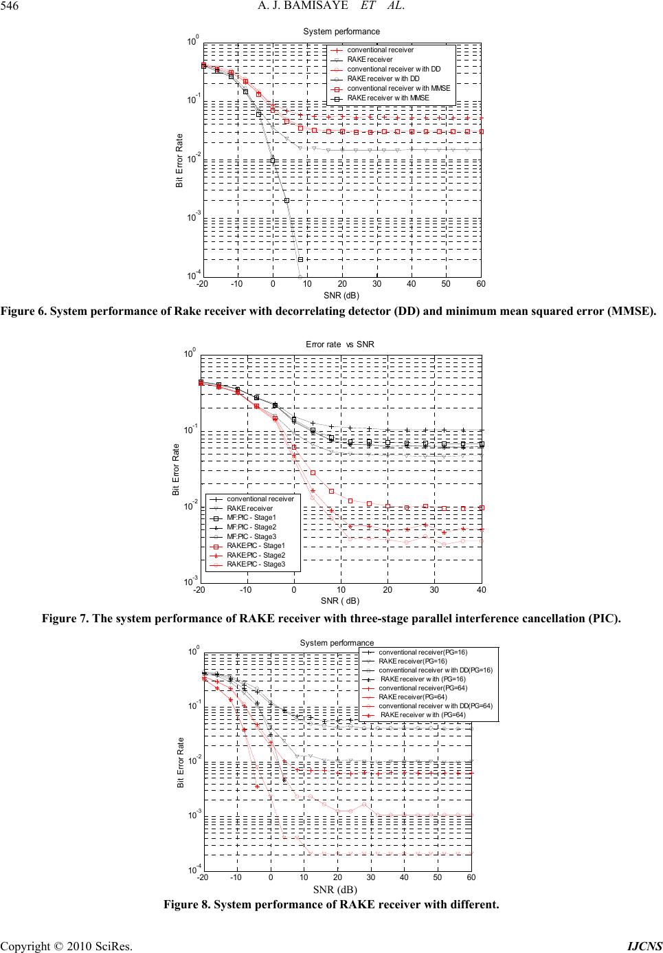
ting Detector and
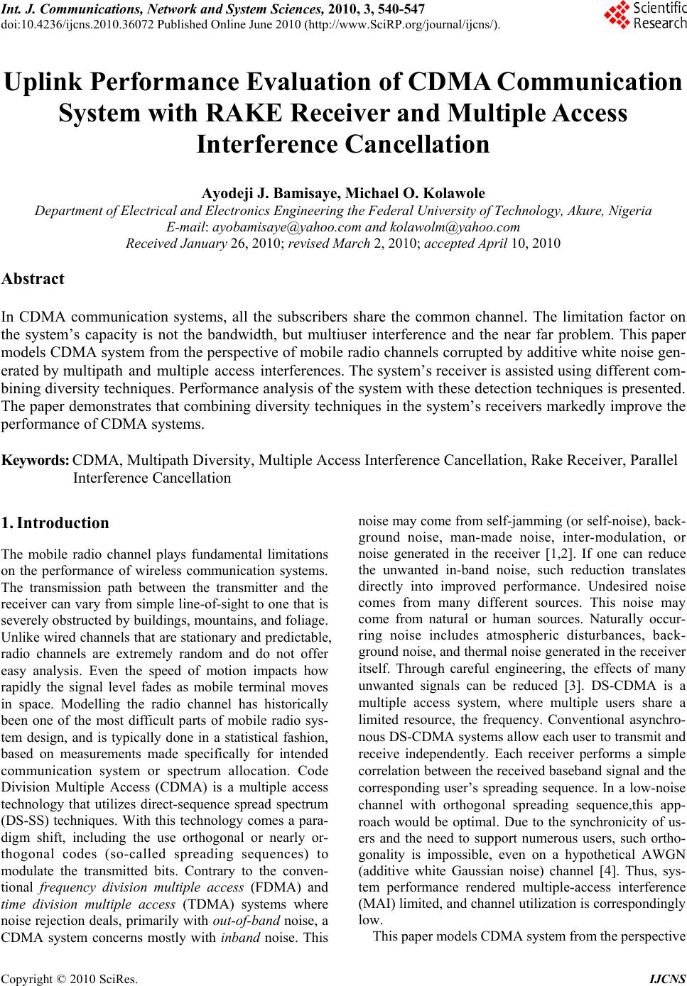
M
is clearly stated. It is assumed that the system
us
ta is obtained by passing the soft
de
Simulations were performed for 10 active users sending
to 100total of 10000 symbols. The
in cance-
lli
Similar parameters used in 1.3.1 are used in this analysis
In add are updated ran-
.
Th
ectively, while other
pa
performance is the
sa
effect of one user upon another. This is, in fact, the
intuitive motivation for interference cancellation scheme.
The difference between multistage receivers and suc-
cesssive interference canceller (SIC) receivers is that
stead of using previous bit decisions to cancel interfer-
eence from desired user’s signal as in SIC, tentative de-
cisions on each user are used to improve signal quality
[10]. Receiver structure is called multistage, since when
decisions are made, they can be used to either make a
final decision on data or to enhance the signal through
cancellation. Reference signals are based on initial bit
estimates, which are then subtracted from received signal
to produce a cleaned spread signal for next stage. Since
all signals are detected at each stage simultaneously,
multistage receivers are also called parallel interference
cancellers (PIC). A two-user multistage receiver is
shown in Figure 2. The p-stage receiver outputs are
1,pp
k
yt
, where 1, 2,p.
Instead of a conventional (matched filter) receiver
a
1]. Performance of PIC is best when received signal
powers are equal. Capacity of the system is limited by
hardware.
1.3. Simulati
Performance evaluations were p
scenarios using:
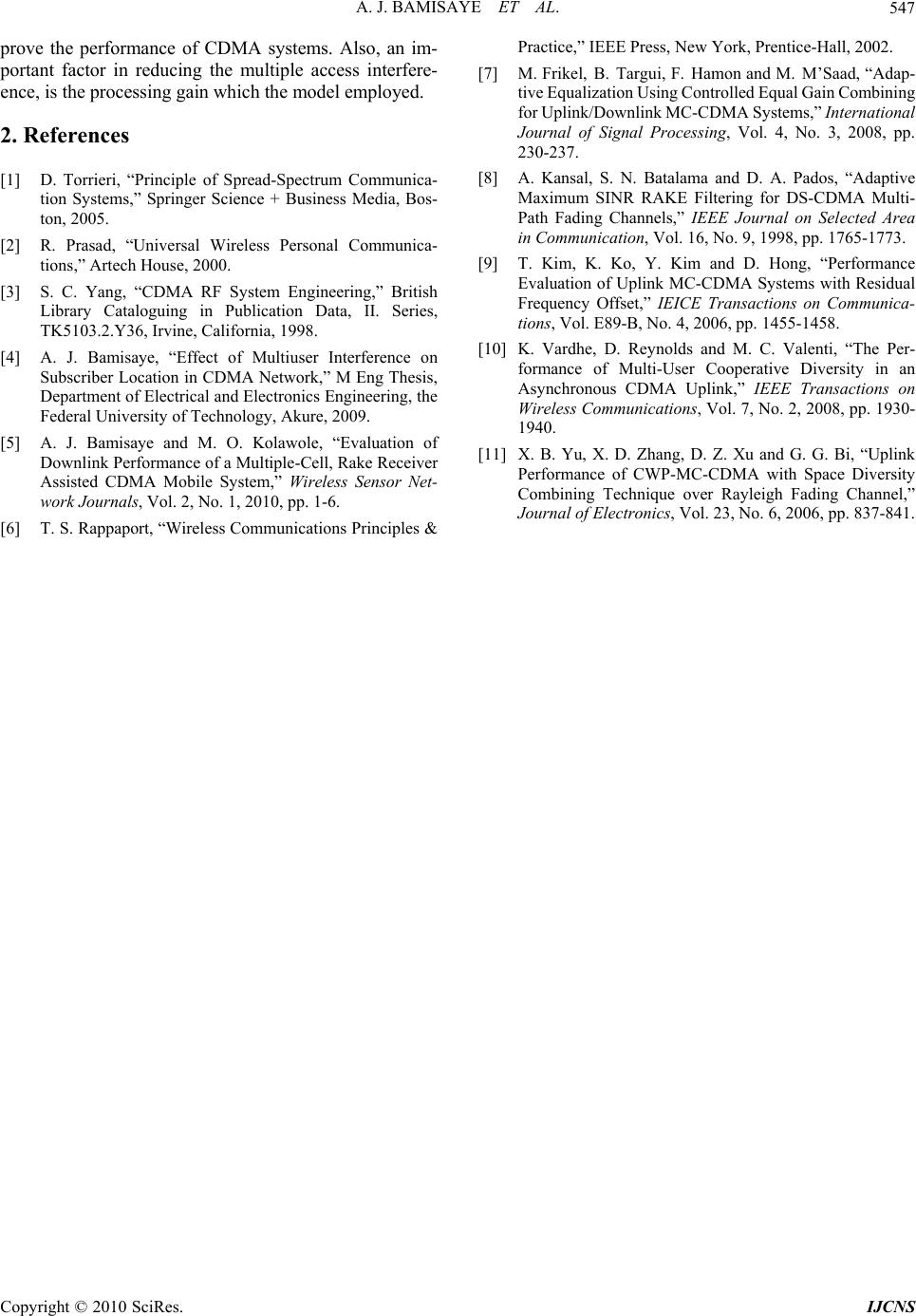
1) Conventional matched filters receiver with PIC
(parallel interfere
2) Rake receiver with PIC;
3) Rake receiver with Decorrela
MSE; and
4) Conventional matched filters receiver and rake re-
ceiver.
For each analysis, the number of users’ symbols tran-
smitted
es unencoded BPSK signal, as well as no pulse-
shaping filter. Each transmitted MS within each loop
sends a block of data bits of known length. The input of
MUD (multi user detection) is the soft decision of either
rake receiver or conventional matched filters. In the
simulation, the sub-optimum linear MUD decorrelating
detector, linear minimum mean squared error (LMMSE)
detector, and nonlinear sub-optimum PIC were built for
the multishot model.
In relation to the decision operation, the hard decision
output of received da
cision output through the design circuit, which repre-
sents any sign function for BPSK. Also, we make the
number of channel paths P equal the number of fingers M
to make the rake receiver simpler in structure. In a less
equivalent case, that is, when M < P or M > P, the system
performance degrades. Therefore, the matched case pro-
vides the optimally achievable performance reference.
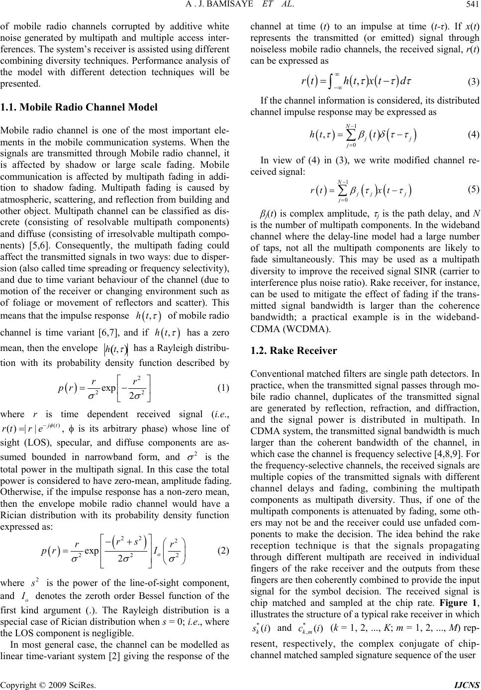
1.3.1. Performance of Conventional Matched Filters
Receiver with PIC
10 symbols within each loop. The maximum loop equals
. The users send a
data are then spread by Walsh code and scrambled by
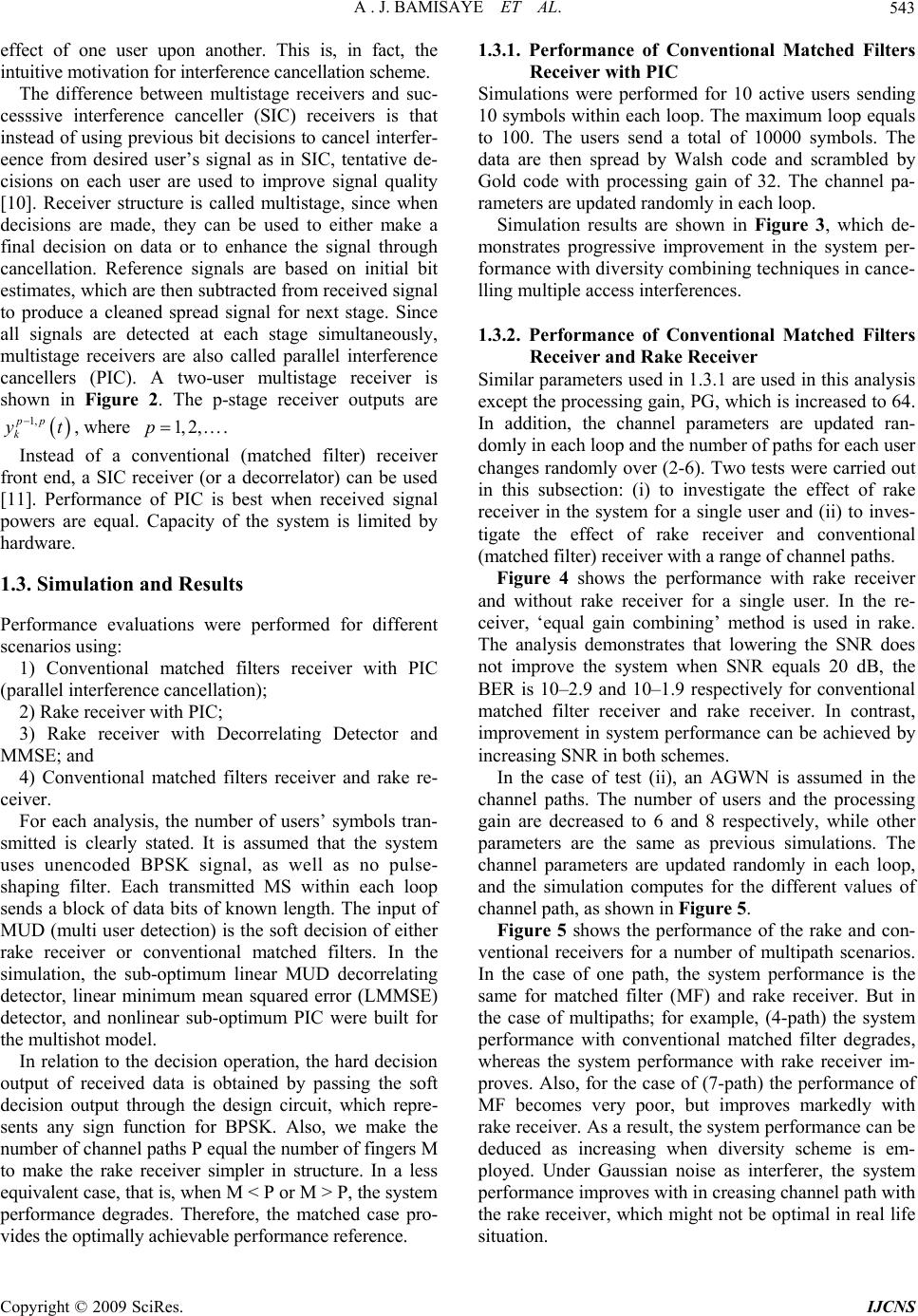
Gold code with processing gain of 32. The channel pa-
rameters are updated randomly in each loop.
Simulation results are shown in Figure 3, which de-
monstrates progressive improvement in the system per-
formance with diversity combining techniques
ng multiple access interferences.
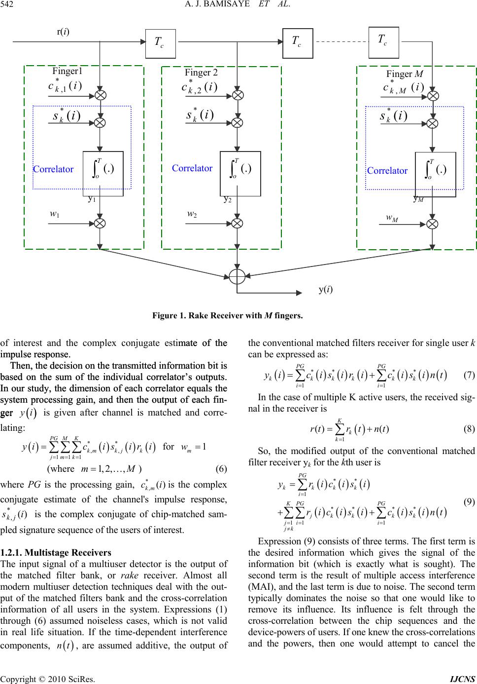
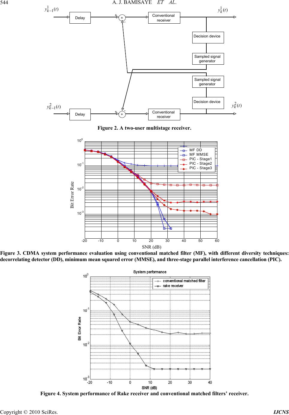
1.3.2. Performance of Conventional Matched Filters
Receiver and Rake Receiver
except the processing gain, PG, which is increased to 64.
ition, the channel parameters
domly in each loop and the number of paths for each user
changes randomly over (2-6). Two tests were carried out
in this subsection: (i) to investigate the effect of rake
receiver in the system for a single user and (ii) to inves-
tigate the effect of rake receiver and conventional
(matched filter) receiver with a range of channel paths.
Figure 4 shows the performance with rake receiver
and without rake receiver for a single user. In the re-
ceiver, ‘equal gain combining’ method is used in rake
e analysis demonstrates that lowering the SNR does
not improve the system when SNR equals 20 dB, the
BER is 10–2.9 and 10–1.9 respectively for conventional
matched filter receiver and rake receiver. In contrast,
improvement in system performance can be achieved by
increasing SNR in both sche m e s.
In the case of test (ii), an AGWN is assumed in the
channel paths. The number of users and the processing
gain are decreased to 6 and 8 resp
rameters are the same as previous simulations. The
channel parameters are updated randomly in each loop,
and the simulation computes for the different values of
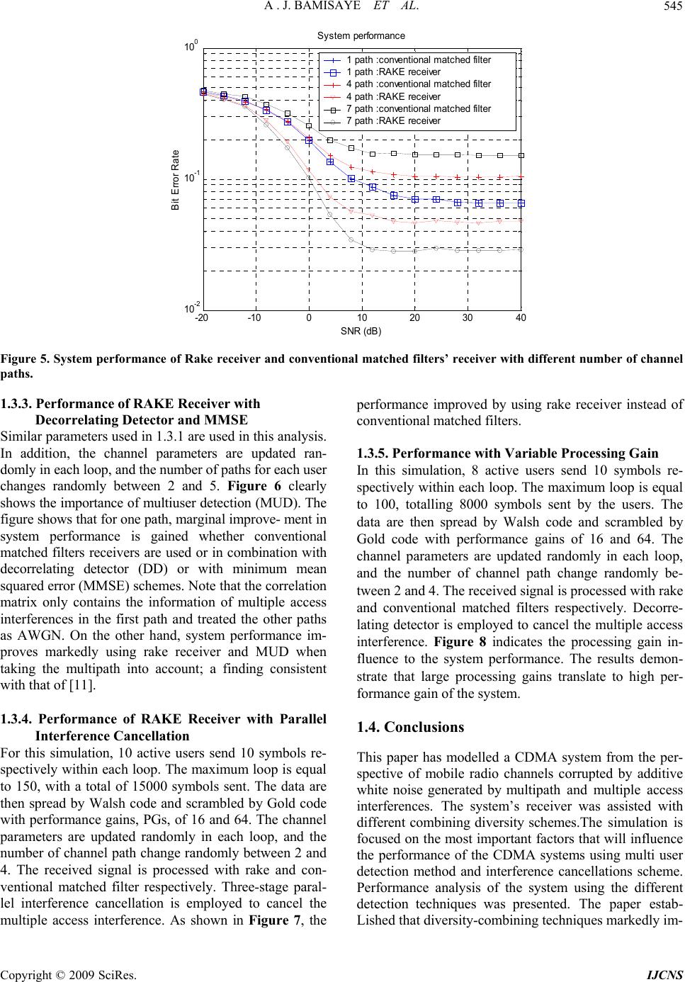
channel path, as shown in Figure 5.
Figure 5 shows the performance of the rake and con-
ventional receivers for a number of multipath scenarios.
In the case of one path, the system
me for matched filter (MF) and rake receiver. But in
the case of multipaths; for example, (4-path) the system
performance with conventional matched filter degrades,
whereas the system performance with rake receiver im-
proves. Also, for the case of (7-path) the performance of
MF becomes very poor, but improves markedly with
rake receiver. As a result, the system performance can be
deduced as increasing when diversity scheme is em-
ployed. Under Gaussian noise as interferer, the system
performance improves with in creasing channel path with
the rake receiver, which might not be optimal in real life
situation.
Copyright © 2009 SciRes. IJCNS