Int'l J. of Communications, Network and System Sciences
Vol. 5 No. 5 (2012) , Article ID: 19479 , 8 pages DOI:10.4236/ijcns.2012.55033
Corporate Intranet Security: Packet-Level Protocols for Preventing Leakage of Sensitive Information and Assuring Authorized Network Traffic
New Jersey Institute of Technology, University Heights, Newark, USA
Email: {verb, rr8}@njit.edu
Received March 23, 2012; revised April 20, 2012; accepted May 7, 2012
Keywords: Corporate security; authorized traffic; Data Leakage; Cryptographic Token; Authentication; Trusted Authorities; Toom-Cook Algorithm
ABSTRACT
Securing large corporate communication networks has become an increasingly difficult task. Sensitive information routinely leaves the company network boundaries and falls into the hands of unauthorized users. New techniques are required in order to classify packets based on user identity in addition to the traditional source and destination host addresses. This paper introduces Gaussian cryptographic techniques and protocols to assist network administrators in the complex task of identifying the originators of data packets on a network and more easily policing their behavior. The paper provides numerical examples that illustrate certain basic ideas.
1. Introduction
Modern Internet Protocol (IP) networks deployed within large organizations face a multitude of threats, both from within the network borders and from the Internet. Network administrators are inundated with new network security compliance challenges that are mandated by myriad government agencies and industry groups. Security breaches such as data leakage and industrial espionage often originate within the corporate firewall and are therefore difficult to detect. A new system of authentication is needed to enable the network as a whole, along with its administrators, to identify the users, who are generating packets traversing the network. By tagging all IP packets on the corporate local-area network (LAN) with identity information, network devices and administrators can monitor, audit and shape the flow of data using familiar user identities instead of the traditional IP quintuple.
Remark 1: Large corporate networks are made up of multiple local-area networks (LANs) connected together via a wide-area network (WAN). Packets are tagged within each individual LAN and the tag is verified by devices within both the LAN and WAN.
2. Related Work
Packet marking has been used to solve a broad array of problems in the networking space. Quality of Service (QoS) is accomplished in many networks by tagging IP packets with a TOS or DSCP [1] value to indicate service discrimination on the network. By augmenting each IP packet with an additional header, the IPSEC authentication header [2] provides end-to-end packet integrity, authentication and replay protection. The Microsoft CHOICE network [3] was designed to secure wireless Internet access in public places. Their research leveraged packet marking to tag packets with a user identifying cryptographic token. As traffic passes through a central server, the token is examined and used to verify user identity and enforce access control. It is widely accepted that distributed denial-of-service attacks can be mitigated with an efficient mechanism to discover and throttle the source of the attacking packets. Packet marking has been employed as a possible solution to this problem [4-6], these schemes in particular utilize unused or underutilized bits in the IP header to facilitate the traceback algorithm. In order to secure modern military networks, [7] introduces a scheme, which marks IPv6 packets with an extension header containing an elliptic curve digital signature. Hardware contained within all network nodes validates the public-key based signature for authenticity before accepting a packet. In order to facilitate resource access control at the network edge, [8] explores the use of packet marking for authenticating traffic between end users and ISP edge routers. The use of this technique facilitates the secure transmission of real-time data along with securing access to subscription-based content. A proposed vendor-neutral firewall authentication and identity-based packet filter scheme based on packet marking is discussed in [9]. This scheme introduces identity carrying IPv4 option headers to inform mid-stream firewalls of user identity in order to enhance the standard quintuple-based firewall packet filters. Packet marking is employed to realize path pinning in packet-switched networks [10]. Path pinning allows IP networks to behave in a manner similar to traditional circuit-switched networks. In this paper, we explore using packet marking for endpoint-to-network security. In other words, we wish to make the network as a whole aware of user identities in addition to host identities by marking each packet with authentication information. As a result, this information can be interpreted and acted upon by network devices during packet routing.
3. Protocol Description
The goal of the Corporate Intranet Security (CIS) protocol is to insert into each packet an additional header which securely identifies the user responsible for its origination. Special devices on the network can interpret this header and determine the originating user and the authenticity of the packet. These devices can additionally enforce policies (such as packet prioritization and/or auditing) based on the detected identities. A single trusted entity is responsible for all identities existing on the network and has the ability to share this information with the appropriate security devices. Figure 1 illustrates such a network. An analogous scheme introduced in [7] relies on public-key cryptography and specialized hardware installed on all network nodes. Our scheme proposes symmetric encryption in order to eliminate the need for dedicated cryptographic coprocessors.
3.1. Major Participants and Components
Network Users: Each network user is identified by the appropriate subscript index . Every user has an associated user name
  (such as
  = Alice and
  = Bob), password
  and randomly assigned temporary user identifier (uid)
 .
.
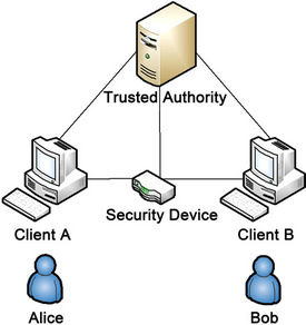
Figure 1. Network overview.
Corporate Traffic Controller (CTC): CTCs can be any network device that has the requisite processing power to validate user identities on a per-packet basis. Additionally, CTCs can influence the flow of traffic within the network (i.e. firewalls, routers, packet shapers, etc). Similar to network users, CTCs are identified by a subscript index  (
( ) along with an associated username
  and password
 .
.
Trusted Authority (TA): TAs are responsible for the authentication of users on the network and the generation of the associated cryptographic keys. They are also responsible for sharing identity information with the appropriate CTCs. For redundancy purposes, there may be multiple TAs. However for the sake of simplicity, we consider only one.
Authentication Key (AK): When a user or CTC transmits its private information to the TA, it is desirable for this information to be encrypted. To that end, the AK is used to encrypt the channel between  and the TA. The joint AK between the user
  and the TA is a Gaussian integer denoted:
 (1)
(1)
The joint AK between the CTC and the TA is denoted:
 (2)
(2)
User Digital Signature: Each user is required to digitally sign the contents of their packets and embed such signature within the packet. While there are a multitude of methods for introducing a user’s signature [11-13], our primary concern in choosing a digital-signature scheme is to minimize the processing time-delay required for its verification at the CTC. Before creating the digital signature, a predetermined randomly generated set of bytes are appended to the packet (i.e. salted) in order to provide greater crypto-immunity. This salt is denoted: .
.
User Digital Signature Key: The TA selects a key for each user  in order to create the user digital signature. The digital signature key for user
  is another Gaussian integer denoted:
 (3)
(3)
Each digital signature key  is valid for a set period of time and has an associated expiration time
 .
.
3.2. Protocol Overview
User Actions: In order to embed the necessary identity information into every packet, each user  must execute the following steps:
1) User Authentication Exchange—a process in which user  proves its identity to the TA and obtains the necessary data required to communicate on the network.
2) Digital Signature Process—the algorithm used to create a digital signature for each outbound packet.
3) Packet Marking—the process of embedding a digital signature into each outbound packet.
CTC Actions: The CTC must also execute a series of steps in order to perform its duties:
1) CTC Authentication Exchange—a process in which the user that represents a CTC  proves its identity to the TA and obtains the necessary data to validate digitally signed packets traversing the network.
2) Identity Verification & Policy Enforcement—the process which the CTC uses to inspect, validate and optionally execute policies against arriving packets.
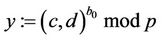
3.3. User Authentication Exchange (UAX)
A user  must identify itself to the TA before it can participate on the network. The authentication process is as follows:
1.1. User  requests a UAX from the TA.
2.1. The TA selects a large prime p and a pair of distinct positive integers  for which the inequality
 (4)
(4)
Remark 2: If p mod 4 = 3, then (4) automatically holds for every Gaussian integer.
3.1. The TA transmits p and g to the user .
.
4.1. The user  randomly selects a large secret integer
  satisfying the inequality
 (5)
(5)
5.1. Correspondingly, the TA also selects a large secret integer  on the same interval:
 . (6)
. (6)
6.1. User  computes
 (7)
(7)
and transmits  to the TA.
7.1. The TA computes
 (8)
(8)
and transmits y to user .
.
8.1. User  computes
 (9)
(9)
9.1. The TA computes
 (10)
(10)
It is easy to verify that the equation
 (11)
(11)
holds for every .
.
Let  (12)
(12)
where  is the AK between user
  and the TA.
10.1. User  applies its AK
  to encrypt its username and password and transmits them to the TA:
 (13)
(13)
11.1. Upon verification of (13), the TA generates the following:
1)  —a randomly generated unique 16-bit value representing user
 . This number cannot be reused until the time
  is reached.
2)  —a randomly generated 32-bit value that is appended to each packet in order to strengthen the digital signature.
3)  —the digital signature key used to construct the digital signature.
4)  —the coordinated universal time (UTC) for which the above values cease to be valid on the network.
12.1. The TA, using the negotiated authentication key  encrypts the above quadruple and transmits it to the user
 :
:
 (14)
(14)
Once the UAX process is complete, the user has all of the information necessary to begin the Digital Signature Construction and Packet Marking processes. Furthermore, once time  is reached, user
  must only execute steps 10.1-12.1 in order to renew its ability to use the network.
3.4. CTC Authentication Exchange (CAX)
A CTCt must authenticate with the TA in a similar manner as network users do. In fact, steps 1.1-10.1 of the UAX process are analogously replicated in the CAX process, however the CTC submits its username  and password
 . The new additional steps are as follows:
11.2. Upon verification of (13) and identifying the user  as a CTC, the TA, using the negotiated authentication key
  encrypts the quadruple
  for all j and transmits them to the CTCt.
12.2. As new users register with the TA via the UAX process, the TA must transmit these values to the CTCt. Furthermore, when time  arrives for all j in the CTC’s memory, all values with the associated subscript j are to be purged.
After completing the final steps, the CTCs have the information necessary to validate the user identities of arriving packets.
3.5. Digital Signature
A digital signature scheme for the application described in this paper must meet a number of criteria in order to be effective:
1) Speed—signature construction and verification must be performed as quickly as possible in order to minimize packet transmission delay.
2) Security—the signature must provide adequate security to prevent falsification of the packet header. However, due to frequent key rotations, strength is secondary to speed.
Remark 3: There is a tradeoff between the level of security and speed of signature generation. We have intentionally relaxed the level of crypto-immunity for the sake of decreasing signature generation time.
3) Size—the signature must not take excessive space in order to minimize the overhead within the packet.
4) Consideration of mutable fields—the internet protocol (IP) header consists of a number of fields:
• Fields that can be modified while the packet is in transit are referred to as mutable fields;
• Fields that remain constant throughout the transmission process are known as non-mutable fields.
An effective packet digital signature algorithm must ignore the mutable fields within the IP header and process the non-mutable fields; otherwise the signature will be invalidated.
3.6. Digital Signature Process
The signature generation process (see Figure 2) consists of the following:
1) The user digital signature key .
.
2) An MD5 [14,15] hash denoted as m. The MD5 algorithm takes as input a series of bytes of arbitrary length and produces as output a 128-bit hash. The hash m is constructed over the concatenation of non-mutable IP header fields denoted as β, packet payload denoted as γ and the salt is .
.
3)  (15)
(15)
4) A signature s is computed as follows:
 (16)
(16)
5) The signature s is truncated by taking the most significant 96-bits and discarding the rest. This is done to satisfy space constraint requirements and is similar to the process specified in [16].
3.7. Packet Marking
Once the user  has obtained the quadruple of necessary parameters
 , it can begin marking outgoing packets with the security option header. A packet signature is calculated using the algorithm described above and embedded into the security option header; this header is in turn embedded within the packet.
The security option header (see Figure 3) consists of four fields:
1) Code - required by the IP protocol specification, it identifies the option type and contains flags that instruct routers how to process the option.
2) Length - specifies the size of the entire option header.
3)  - the temporary user id value of the user
  that generated this packet. The value
  is determined during the user authentication exchange.
4) User Digital Signature—the output of the Digital Signature process as described above.
Once constructed, the security option header is placed within the IP packet, as shown in Figure 4, and transmitted.
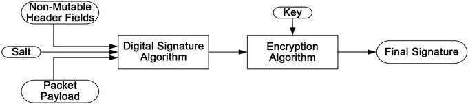
Figure 2. Packet signing process.

Figure 3. Security option header.

Figure 4. Option header placement.
3.8. Identity Verification & Policy Enforcement
As packets traverse the network, they will be processed by one or more CTCs. The role of these devices is to verify the authenticity of each packet and enforce policies based on the outcome. This behavior is further demonstrated in Figure 5. For instance, a corporation may implement a quality of service (QoS) rule that prioritizes all traffic originating from corporate executives. As packets arrive at a CTC, those that are successfully verified as originating from an executive will be prioritized and have their distributed services code point (DSCP) fields updated to reflect their higher priority. Once a CTC performs a CAX, it is provided with the quadruple  for all users. Upon arrival, the
  value in each packet is used to search the CTC’s identity table for the corresponding digital signature key
  and salt
 . A new digital signature is calculated and compared with the signature within the packet. If the values match, the associated policies are then executed against the packet. If the values do not match, the packet can either be dropped or stripped of its option header and transmitted according to policies for unsigned packets. The verification procedure is as follows:
1) The CTC examines the arrived packet  and determines the value
 .
.
2) The CTC searches its identity table for the digital signature key , salt
  and user name
  that corresponds with
 .
.
3) The CTC determines the values of β and γ for the packet  and computes:
 .
.
4) The CTC then computes: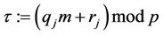 .
.
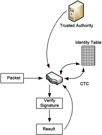
Figure 5. CTC/TA interaction.
5) If , then the CTC confirms the packet originated from user
  and executes the associated policy rules.
6) If , then the CTC detects a possible forgery and either drops the packet, strips the option header or executes other associated policy rules.
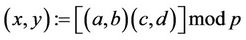
4. Arithmetic of Gaussian Integers
Definition. Let (a,b) and (c,d) be Gaussian integers. Then
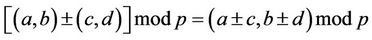 ; (17)
 ; (18)
where the multiplication can be performed faster.
Karatsuba-Ofman algorithm: Let
 (19)
(19)
Compute  (20)
(20)
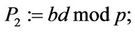 (21)
(21)
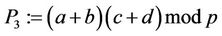 (22)
(22)
Then 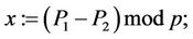 (23)
(23)
 (24)
(24)
Therefore, multiplication of two Gaussians can be performed using three, rather than four multiplications. Hence, the so-called traditional multiplication of complex numbers requires 33.3% more time than the method provided in Karatsuba-Ofman algorithm [17]. In addition, squaring of a Gaussian integer requires two rather than three multiplications. Indeed,

In many cases, an increase in the crypto-immunity of an algorithm requires a corresponding increase in the size of the integers used. For extremely large integers that exceed the capabilities of the host computer, the algorithm proposed by Andrei Toom [18] is instrumental. For illustration, an algorithm for multiplication of triple-long integers (e.g. integers three times the size that the host computer can handle) is presented in the appendix.
5. Numeric Illustration-1
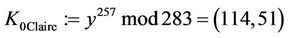
Suppose that TA (called Tom) selected p = 283 and a generator g := (c,d) = (1,2), and transmitted these values to users A and B (called Alice and Bob) and to CTC (called Clair). Suppose now Alice selects a secret integer a = 51; Bob selects a secret integer b = 119; Clair/CTC selects a secret integer c = 257; and Tom selects a secret integer t = 171. Each entity performs the following functions (solutions are found in Table 1):
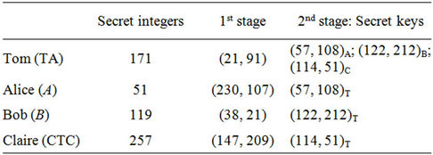
Table 1. p = 283; g = (c,d) = (1,2).
1) Every user computes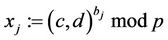 ;
;  and sends
  to the TA:
 ;
; ;
;
2) The TA computes  and transmits y to all corporate users and to the CTC:
 ;
;
3) The CTC computes  and sends
  to the TA:
 ;
;
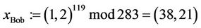
4) The TA computes 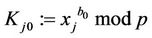 for every
 :
: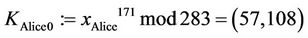 ;
; ;
;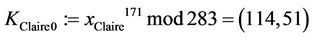 ;
;
5) Every user computes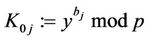 :
: ;
; ;
;
6) The CTC computes: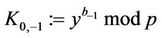 :
: .
.
For the sake of brevity, we will not elaborate on the additional computations required for this protocol. However, this will be addressed in a future publication.
6. Prototype Results
A prototype of the system discussed in this paper was developed in C as a suite of device drivers compatible with Microsoft Windows Vista/Server 2008 and higher systems. On desktop systems, packet marking is handled by a lightweight filter (LWF) driver. On Windows-based CTCs, identity verification & policy enforcement is handled by a Windows filtering platform (WFP) driver. These drivers work in conjunction with user-mode tools and a Linux-based trusted authority which together handle the authentication exchange procedures. On Windows PCs equipped with gigabit Ethernet connectivity and dualcore Intel-based processors, the performance impact is negligible. In order to test the CIS system’s impact on

Table 2. Performance results.
system performance, large files of approximately 1.3 gigabytes were transferred between two end hosts (Alice & Bob) through a CTC (Claire). Table 2 contains the results of these tests.
7. Conclusion
In this paper, we present a technique for transparently identifying users transmitting on a network via packet marking and packet inspection. We also demonstrate a key exchange and digital signature algorithm based on Gaussian integers. By utilizing Gaussian integers for cryptography, we can maintain complexity similar to integerbased schemes while using much smaller prime numbers. Prototypes of the packet marking and inspection components running on dual-processor computers show a modest impact in throughput and CPU utilization. As quadcore and hex-core processors become more popular in the desktop PC space, performance will continue to improve. The preliminary version [19] of this paper was published in proceedings of the 18th International Conference on Software Engineering and Data Engineering.
8. Future Work
Most corporate networks utilize the current generation internet protocol (IPv4) as the network-layer protocol of choice. However, deployment of the next-generation internet protocol (IPv6) within corporations is gaining momentum. The security scheme described in this paper, while based on the IPv4 option header, can be redesigned as an IPv6 extension header. In a future revision, this scheme will be extended to accommodate networks that utilize IPv4, IPv6 or both.
9. Appreciations
The authors wish to express their appreciations to J. Geller, W. Gruver, Yu. Polyakov and I. Semushin for their constructive comments and suggestions that improved the quality of this paper.
REFERENCES
- K. Nichols, S. Blake, F. Baker and D. Black, “Definition of the Differentiated Services Field (DS Field) in the IPv4 and IPv6 Headers,” Request for Comments 2474, 1998.
- S. Kent and R. Atkinson, “IP Authentication Header,” Request for Comments 2401, 1998.
- V. Bahl, A. Balachandran and S. Venkatachary, “The CHOICE Network: Broadband Wireless Internet Access in Public Places,” Microsoft Research, 2000.
- M. Adler, “Trade-Offs in Probabilistic Packet Marking for IP Trace-Back,” Journal of the ACM, Vol. 52, No. 2, 2005, pp. 217-244. doi:10.1145/1059513.1059517
- M. T. Goodrich, “Efficient Packet Marking for LargeScale IP Traceback,” Proceedings of the 9th ACM Conference on Computer and Communications Security, Washington, 27-30 October 2003, pp. 117-126.
- M. T. Goodrich, “Probabilistic Packet Marking for Large-Scale IP Traceback,” IEEE/ACM Transactions on Networking, Vol. 16, No. 1, 2008, pp. 15-24. doi:10.1109/TNET.2007.910594
- C. Candolin, J. Lundberg and H. Kari, “Packet Level Authentication in Military Networks,” 6th Australian Information Warfare & IT Security Conference, Geelong, 24-25 November 2005.
- H. Wang, A. Bose, M. El-Gendy and S. Kang, “IP Easypass: A Light-Weight Network-Edge Resource Access Control,” IEEE/ACM Transactions on Networking, Vol. 13, No. 6, 2005, pp. 1247-1260. doi:10.1109/TNET.2005.860113
- R. D. Rubino, “An Open System for Transparent Firewall Authentication and User Traffic Identification within Corporate Intranets,” Proceedings of the 9th ACM SIGITE Conference on Information Technology Education, Cincinnati, 16-18 October 2008, pp. 113-118. doi:10.1145/1414558.1414591
- B. Parno, A. Perrig and D. Anderson, “SNAPP: Stateless Network-Authenticated Path Pinning,” Proceedings of the 2008 ACM Symposium on Information, Computer and Communications Security, Tokyo, 14 May 2008, pp. 168- 178.
- B. Schneier, “Secrets and Lies: Digital Security in a Network World,” 1st Edition, John Wiley & Sons, New York, 2000.
- B. Verkhovsky, “Fast Digital Signature Hybrid Algorithm Based on Discrete Logarithm, Entanglements of Plaintext Arrays and Factorization,” In: Y. Polyanskov, Ed., 7th International Conference Mathematics Modeling in Physics, Technology, Socio-Economic Systems and Processes, Ulyanovsk University, Ulyanovsk, 2009.
- B. Verkhovsky, “Overpass-Crossing Scheme for Digital Signature,” Proceedings of 13th International Conference on Systems Research, Informatics and Cybernetics, Baden-Baden, 30 July-3 August 2001.
- R. Rivest, “The MD5 Message-Digest Algorithm,” Request for Comments 1321, 1992.
- B. Schneier, “Applied Cryptography: Protocols, Algorithms and Source Code in C,” 2nd Edition, John Wiley and Sons, New York, 1996.
- C. Madson and R. Glenn, “The Use of HMAC-MD5-96 within ESP and AH,” Request for Comments 2403, 1998.
- A. Karatsuba and Yu. Ofman, “Multiplication of MultiDigit Numbers on Automata,” Soviet Physics-Doklady, Vol. 7, 1963, pp. 595-596.
- A. Toom, “The Complexity of a Scheme of Functional Elements Realizingthe Multiplication of Integers,” Soviet Mathematics-Doklady, Vol. 7, 1963, pp. 714-716.
- B. S. Verkhovsky and R. D. Rubino, “Internal Corporative Security: Protocols Preventing Leakage of Sensitive Information and Assuring Authorized Network Traffic in the Domain of Gaussian Integers,” Proceeding of the 18th International Conference on Software Engineering and Data Engineering, Las Vegas, 22-24 June 2009, pp. 244- 249.
- R. Crandall and C. Pomerance, “Prime Numbers: Computational Perspective,” Springer, New York, 2001.
APPENDIX
A1. Multiplication of Triple-Long Integers
Goal: To compute C = AB
where A = 102na2 + 10na1 + a0;
and B = 102n
b2 + 10nb1 + b0;
Inputs: a2,a1,a0,b2,b1,b0,n.
Consider A(x):=a2x2+a1x+a0;
and B(x): = b2x2 + b1x + b0;
Then C(x) = A(x)B(x)
= (a2x2 + a1x + a0)(b2x2 + b1x + b0)
= c4x4 + c3x3 + c2x2 + c1x + c.
Outputs: c4,c3,c2,c1,c0; {if we know them, and x: = 10n we can compute the product AB}.
Efficiency requirement: minimal number of multiplications.
A2. The Algorithm
Step 1: Compute five products P0, ···, P4:
P0 = a0b0 = c0;
P1 = (a2 + a1 + a0)(b2 + b1 + b0);
P2 = (a2 – a1 + a0)(b2 – b1 + b0);
P3 = (4a2 + 2a1 + a0)(4b2 + 2b1 + b0);
P4 = (4a2 – 2a1 + a0)(4b2 – 2b1 + b0);
Step 2: Compute D1:= (P1 – P2)/2; S1:=(P1 + P2)/2;
D2:= (P3 – P4)/4; S2:=(P3 + P4)/8;
Step 3: Compute c3 = (D2 – D1)/3;
c1 = D1 – c3;
Step 4: Compute c4 = (S2 – S1)/3 + c0/4;
c2 = S1 – c0 – c4;
Step 5: C = 104nc4 + 103nc3 + 102nc2 + 10nc1 + c0.
A3. Algorithm Validation
P0 = C(0) = a0b0 = c0;(A0)
P1 = C(1) = (a2 + a1 + a0)(b2 + b1 + b0)
=c4+c3+c2+c1+c0;(A1)
P2 = C(– 1) = (a2 – a1 + a0)(b2 – b1 + b0)
=c4 – c3 + c2 – c1 + c0; (A2)
P3 = C(2) = (4a2 + 2a1 + a0)(4b2 + 2b1 + b0)
=16c4 + 8c3 + 4c2 + 2c1 + c0; (A3)
P4 = C(–2) = (4a2 – 2a1 + a0)(4b2 – 2b1 + b0)
=16c4 – 8c3 + 4c2 – 2c1+c0;(A4)
We have four simple linear equations with four unknowns c4, c3, c2, c1, and c0:=a0b0.
Let’s demonstrate how to find c4, c3, c2, c1 if we know P0, P1, ···, P4.
Subtract (A2) from (A1):
D1:= (P1 – P2)/2=c3 + c1;(A5)
Subtract (A4) from (A3):
(P3 – P4)/4 = 4c3 + c1;(A6)
Solve two equations with two unknown c3 and c1:
Subtract (A5) from (A6):
c3 = [(P3 – P4)/4 – D1]/3;(A7)
c1 = (P1 – P2)/2 – c3.(A8)
We derive for c2 and c4 an analogous system of linear equations. IndeedAdd (A1) and (A2):
S1:= (P1 + P2)/2 – c0 = c4 + c2;(A9)
Add (A3) and (A4):
(P3 + P4 – 2c0)/8 = 4c4 + c2.(A10)
Solve two equations with two unknown c4 and c2.
Subtract (A9) from (A10):
c4 = [(P3 + P4 – 2c0)/8 – S1]/3;(A11)
c2 = (P1 + P2)/2 – c0 – c4.(A12)
Therefore, (A1)-(A12) describe an algorithm for the multiplication of triple-long integers that uses five products instead of nine.
Compute D2:= (P3 – P4)/4 and S2:= (P3 + P4)/8. (A13)
A4. Integrality of Coefficients c0, c1, ···, c4
PropositionA1: Every coefficient c0, c1, ···, c4 is an integer if every ak and bk is an integer.
Proof: Let us show that c3 in (A7) is an integer. First of all, (A5) and (A6) are integers, since definitions (A1) and (A2) imply that (P1 – P2)mod2 = 0 and, analogously, definitions (A3) and (A4) imply that (P3 – P4)mod4 = 0.
Indeed, in the latter case:
(P3 – P4)mod4
= [(4a2 + 2a1 + a0)(4b2 + 2b1 + b0)
– (4a2 – 2a1 + a0)(4b2 – 2b1 + b0)]mod4
= [(2a1 + a0)(2b1 + b0)
– (– 2a1 + a0)(– 2b1 + b0)] mod4
= [(2a1 + a0)(2b1 + b0) – (2a1 + a0)(2b1 + b0)]
= 0.
On the other hand, since gcd(3,4) = 1, in a proof that c3 is an integer it is sufficient to show that 4c3mod3 = 0.
Indeed4c3mod3 = [(P3 – P4) – 2(P1 – P2)]mod3
= [(a2 + 2a1 + a0)(b2 + 2b1 + b0)
– (a2 + a1 + a0)(b2 + b1 + b0)
– 2(a2 + a1 + a0)(b2 + b1 + b0)
+ 2(a2 + 2a1 + a0)(b2 + 2b1 + b0)]mod3
= 0;
therefore, 4c3mod3 = 0.
Analogously, a reader of this paper can demonstrate that c4 is also an integer.
Q.E.D.
A5. Numeric Illustration
Let A = 311593 and B = 271628; compute C = AB.
Now let a2:= 31; a1:= 15; a0:= 93; b2:= 27; b1:= 16; b0:= 28 and x:= 100.
Then c0 = P0 = a0b0 = 93 × 28 = 2604;
P1 = (31 + 15 + 93)(27 + 16 + 28) = 139 × 71 = 9869;
P2 = (31 – 15+93)(27 – 16+28)=109 × 39=4251;
P3 = (4 × 31 + 2 × 15 + 93)(4 × 27 + 2 × 16 + 28)
= 247 × 168 = 41496;
P4 = (4 × 31 – 2 × 15 + 93)(4 × 27 – 2 × 16 + 28)
= 187 × 104 = 19448;
D1 = (9869 – 4251)/2 = 2809;
S1 = (9869 + 4251)/2 = 7060;
D2 = (41496 – 19448)/4 = 5512;
S2 = (41496 + 19448)/8 = 7618;
c3 = (5512 – 2809)/3 = 901;
c1 = (2809 – 901) = 1908;
c4 = (7618 – 7060)/3 + 2604/4 = 186 + 651 = 837;
c2 = 7060 – 2604 – 837 = 3619;
C = 1004 × 837 + 1003 × 901 + 1002 × 3619
+100 × 1908 + 2604
= 83700000000 + 901000000 + 36190000
+ 190800 + 2604 = 84637383404
= AB = 311593 × 271628.
Computational complexity of Toom’s algorithm is discussed in [20].