Journal of Electromagnetic Analysis and Applications
Vol. 5 No. 8 (2013) , Article ID: 35487 , 6 pages DOI:10.4236/jemaa.2013.58050
Investigation of Ground Frequency Characteristics
![]()
Electrical Engineering Department, Assiut University, Assiut, Egypt.
Email: m_a_niel@yahoo.com
Copyright © 2013 Mohamed Nayel. This is an open access article distributed under the Creative Commons Attribution License, which permits unrestricted use, distribution, and reproduction in any medium, provided the original work is properly cited.
Received April 8th, 2013; revised May 15th, 2013; accepted July 1st, 2013
Keywords: Ground; Transient; Four Electrode Method; Frequency; Impedance
ABSTRACT
Four-electrode method is one of the well-known methods in measuring ground resistivity. But, most faults currents and lightning currents have high frequencies components. It is proposed to develop this method to study ground frequency characteristics. A step like current was injected into ground to measure the ground impedance. The ground impedance is assumed to be frequency dependent parallel resistance/capacitance. Two equations were proved to estimate ground resistivity and permittivity from four-electrode method. An analytical model was proposed to model studied cases. The four electrodes are divided to equal spheres and complex image method had been used to satisfy the boundary conditions and penetration depth effects. The calculated results show good agreement with the measured results.
1. Introduction
When designing a grounding system for a specific performance objective, it is necessary to accurately measure the ground resistivity of the site where the ground is to be installed. Grounding system design is an engineering process that removes the guesswork and “art” out of grounding. It allows grounding to be done “right, the first time”. The result is a cost savings by avoiding change orders and ground “enhancements” [1].
The ground impedance frequency characteristic plays an important role in understanding and designing grounding systems. To investigate this issue, samples of ground are tested in laboratories [2,3]. The characteristics of these samples will be changed due to ground excavation, temperature and humidity. There are other methods used in prediction of ground parameters and it depends on electromagnetic wave transmitted and reflected from ground or grounding system analysis [4,5].
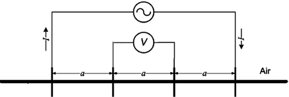
Grounding resistivity measuring methods depend on injecting a current through the ground via the probe electrodes. The current flowing through the ground (a resistive material) develops a voltage/potential difference. There are different methods [6,7] such as, four electrode method, deep electrode method and two electrode method to measure and obtain ground resistivity. The most accurate method in practice of measuring the average resistivity of large volumes of undisturbed earth is the four-electrode method. The electrode configurations commonly used for ground resistivity measurements are the Wenner and Schlumberger, illustrated in Figures 1(a) and (b), respectively. Approximating the current electrodes by hemispheres, the apparent soil resistivity ρapp can be computed using the following Equations [1]:
Wenner Method: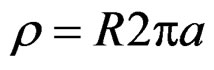 (1)
(1)
Schlumberger Method: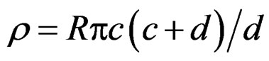 (2)
(2)
When the adjacent current and potential electrodes are close together, the measured ground resistivity is indicative of surface ground characteristics. When the electrodes are far apart, the measured ground resistivity is indicative of average deep ground characteristics throughout a much larger area.
This paper studies the frequency dependence of ground impedance by injecting a step like current in outer electrode of four electrodes method. By using successive image method, four electrodes are modeled in ground with permittivity and conductivity parameter of ground. The ground impedance by the proposed method is studied for different ground parameters and different frequencies.
2. Experimental Setup
The ground resistivity and permittivity is obtained from measured voltage and current waveforms due to wave propagation in the ground to study the effect of frequency.
 (a)
(a)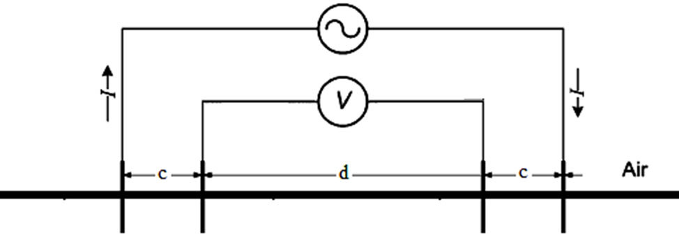 (b)
(b)
Figure 1. Four electrodes configurations: (a) Wenner Method; (b) Schlumberger Method.
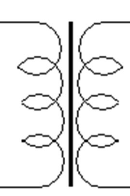
Figure 2(a) illustrates an experimental setup of four electrode method for ground impedance measuring. A step-like current of 20 nsec rise time is injected from a pulse generator (PG) of 500V. The pulse generator injects the current as charge/discharge cable, so, the injected current is not equal to return current. The four electrode method needs to inject current in outer electrode and return the same current from the other side outer electrode. To overcome the unbalance of pulse generator and connection cable a balance transformer. Figure 2(b), is used to convert unbalance current/voltage to balance current/voltage at high frequency. The balance transformer is connected at the end of connected cable to the pulse generator as shown in Figure 2(a). The current is measured by a CT (Peason model 2877, bandwidth from 300 Hz to 200 MHz), and recorded by a digital oscilloscope (Tektronix TDS 3054 m, bandwidth 500 MHz). Transient voltages were measured by a voltage probe (TEKTRONIX P6139A, bandwidth 500 MHz). The field measurements were carried out in Doshisha University yard site.
The current rise time 20 ns is injected for different distances between electrodes. Four electrodes are buried in the ground, as shown in Figure 1(a), all at depth 0.2 m and spaced (in a straight line) at intervals 2 m between the inner electrodes and 4 m between the outer electrodes.
3. Measured Results
A current, as shown in Figure 3, is injected in electrode (C1) and collected from the outer electrodes (C2) and the two voltages of the two inner electrodes (P1 and P2) , as shown in Figure 4, are recorded with the oscilloscope.
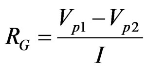
The ground impedance is obtained from the measured voltages and currents (C1, C2, P1, P2). The four electrode method at low frequency is used to obtain the grounding resistance by dividing the potential difference
 (a)
(a)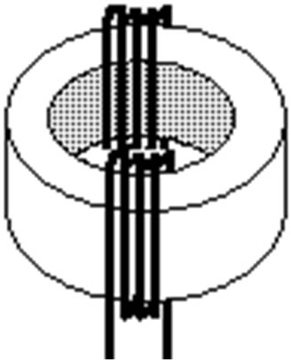 (b)
(b)
Figure 2. Experimental setup of four electrode method: (a) Experimental setup; (b) Balance transformer.
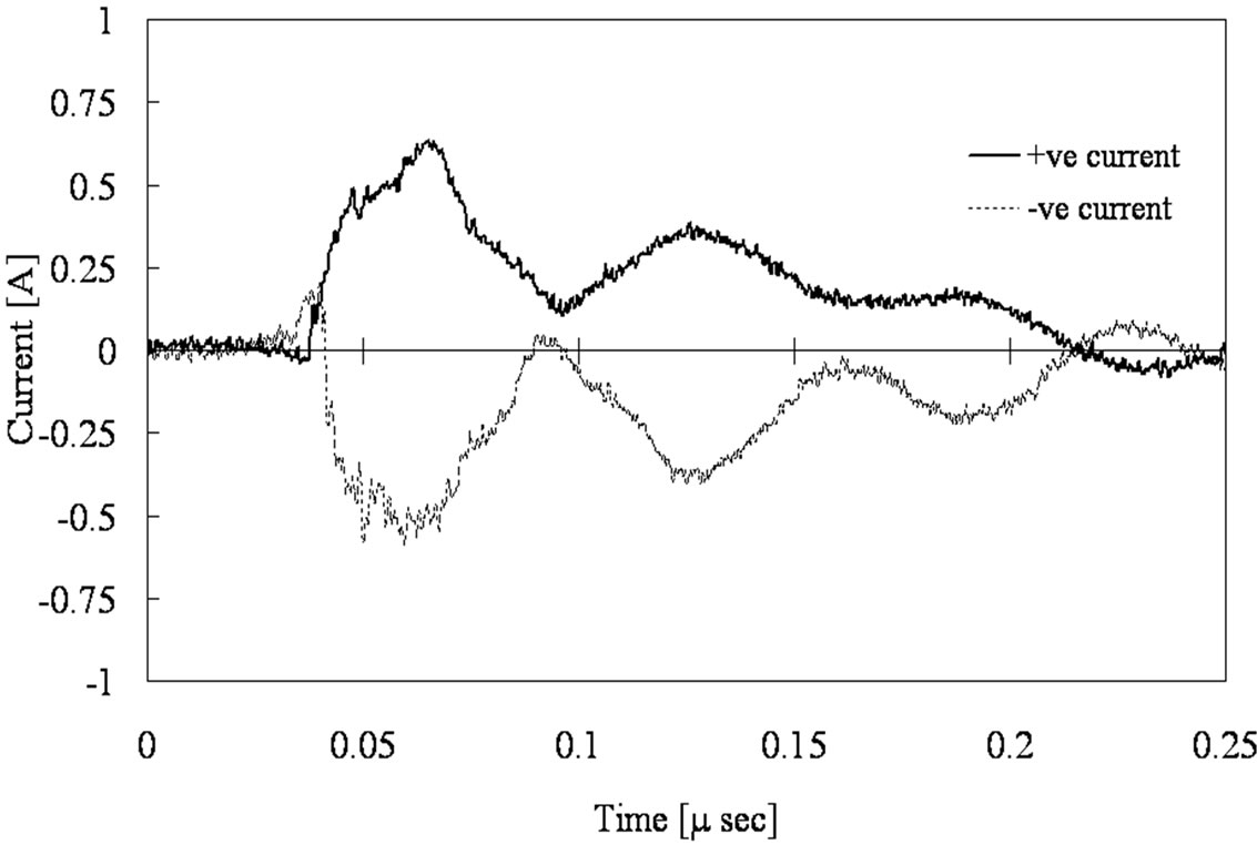
Figure 3. Injected current waveform.
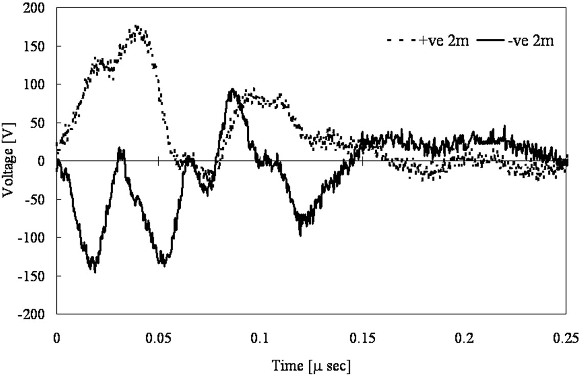
Figure 4. Measured voltage waveforms for non-equal four electrodes method.
between two inner electrodes by the injected current at the outer electrodes as follows:
 (3)
(3)
Finally, complete content and organizational editing before formatting. Please take note of the following items when proofreading spelling and grammar:
Define abbreviations and acronyms the first time they are used in the text, even after they have been defined in the abstract. Abbreviations such as IEEE, SI, MKS, CGS, sc, dc, and rms do not have to be defined. Do not use abbreviations in the title or heads unless they are unavoidable.
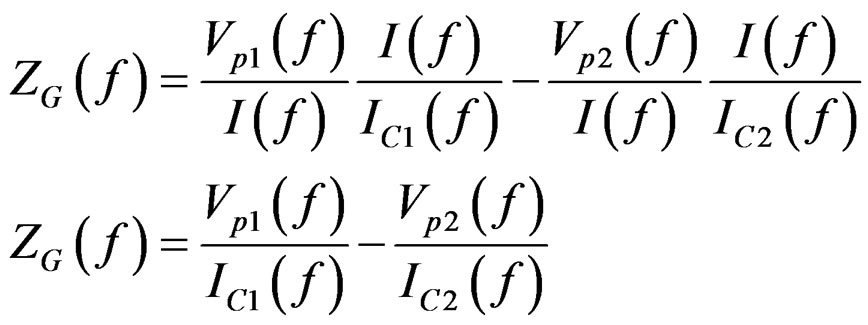
In the same manner the ground impedance at different frequencies ZG(f) is obtained. The current at injected points to ground (C1, C2) is distorted due to the induced voltage between ground and connection wires. The voltage waveforms at any frequency (f) at inner electrodes are reformed to be as a result of current I by multiplying them Vp1 and Vp2 by I/IC1 and I/IC2 as follows:
 (4)
(4)
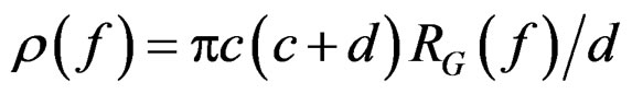
The ground impedance is assumed to be consists of parallel resistance RG(f) and capacitance CG(f). From the obtained ground impedance ZG(f) the ground resistance and capacitance are obtained. The ground resistivity is obtained for non-equal four electrode method by the following equation:
 (5)
(5)
As 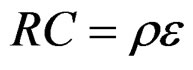 the ground permittivity can be obtained.
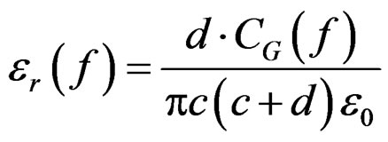 (6)
(6)
Figure 5 shows the calculated ground impedance obtained from the measured results by using Equation (4) and calculated impedance by proposed model in next section. It shows good agreement between measured and calculated results and the dependence of grounding impedance on frequency.
4. Numerical Model
4.1. Penetration Depth Effect
Assume a wave travels into a conducting medium [8]. Equation (7) is a solution of the wave equation for a plane wave traveling in the x direction in the conducting medium.
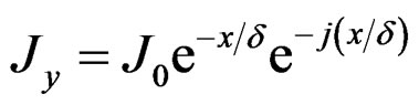 (7)
(7)
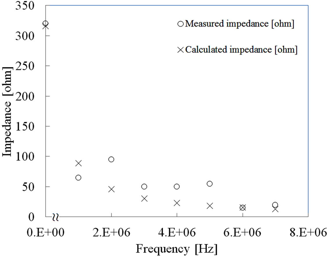
Figure 5. Grounding impedance vs frequency obtained by four electrodes method.
where: d = penetration depth m.
It gives the variation of Ey or Jy in both magnitude and phase as a fuction of x. The electric field Ey or current density Jy deceases to 1/e (36.8%) of its initial value, while the wave penetrates to a distance d called penetration depth [8].
 (8)
(8)
where: f = frequency Hz, µ = ground permeability, s = ground conductivity.
Figure 6 shows the decay of the electric field Ey or currrent density Jy as a function of penetration depth, based on the magnitude of Equation (7). Integrating the absolute value of Equation (7) from x = 0 to ∞ results in E0/d or J0/d. Areas under step functional and exponential curve are equal when step function width is equal to the penetration depth [8] as shown in Figure 6.
It is assumed that all of injected current pass in the area of 1/e depth and the ground resistivity below the penetration depth is proposed to be infinity [9]. The successive image method shown in Figure 7 is proposed to consider the penetration depth in homogenous ground. To make sure that all current pass in the area of 1/e depth, a two layer ground is assumed with a top layer of ground resistaivity r, permitivitty e and depth equal to penetration depth d. The bottom layer is assumed with resistivity = ¥, permitivity = 0 and extended to infinity. The reflication coefficinet between the ground and air is assumed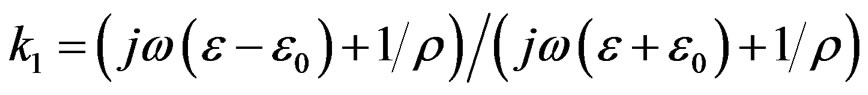 . The bottom layer is assumed with resistivity = ¥, permitivity = 0 and extended to infinity and its reflication coefficient with ground is assumed unity.
The analytical method used to calculate the surface potential profile of the four electrodes and grounding resistance/capacitance assumed each electrode driven into
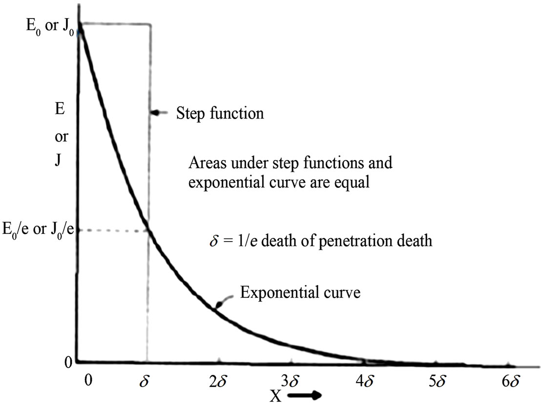
Figure 6. Electric field E or current density J (=sE) as a function of depth of penetration [5].
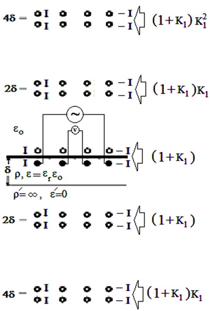
Figure 7. Image map for 4 electrodes at homogenous ground.
the ground as a sphere. As electrode length is very short, each electrode is considered as equipotential surface. The relationship between the voltage and current can be written as:
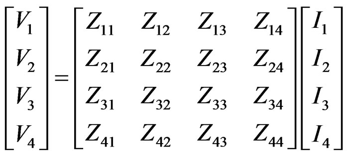 (9)
(9)
where Ij is the current of the jth electrode (j = 1; 2; 3; 4), Vi is the voltage of the jth electrode, Zmn is the mutual impedance element (i.e., mutual impedance between electrode number m and electrode number n), Znn is the self-impedance of the nth sphere.
The elements of the impedance matrix are calculated as equal to:
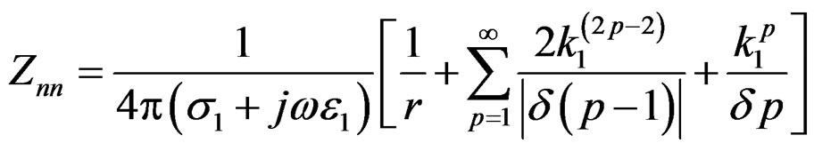 (10)
(10)
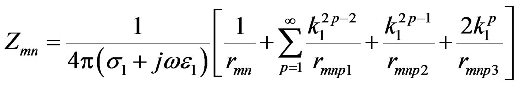 (11)
(11)
where rmn is the distance between mth electrode and nth electrode, rmnp1,2,3,4 are the distances between the mth electrode and the image of the nth sphere and equal to:
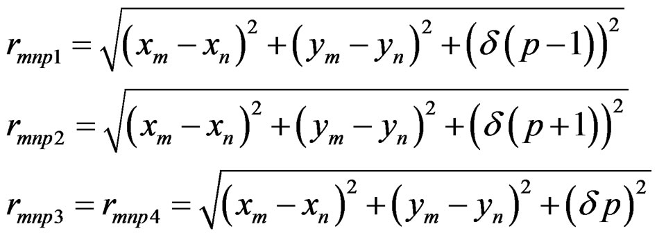
Figure 8 shows the varying of apparent ground impedance for er = 10 and 50 and (a = 1 m, r = 1000 Ω×m) with frequency. The apparent ground impedace decreases more sharbly as the ground relative permittivity increases. This is due to the decrease of the capacitive part of apparent ground impedance with the increase of apparent relative permittivity.
Figure 9 shows the varying of apparent ground impedance for r = 1000 and 500 Ω×m and (a = 1 m, er = 10) with frequency. The apparent ground impedances decreases as the ground resistivity decreases. This is due to the decrease of the decrease of gound resistance.
Figure 10 shows the varying of apparent ground impedance for a =1 and 5 m and (er = 10, r = 1000 Ω×m) with frequency. The apparent ground impedance decreases as the space between electrodes increases.
Figures 8-10 show that, at high frequency until the frequency reach 1 MHz, The apparent ground impedance at low frequency has no change after that it decreases as the frequency increases. This is due to the decrease of capacitive part of ground impedance with frequency.
4.2. Ground Characteristics
The apparent resistance calculated from four electrodes buried in homogenous ground with taking into account the effect of penetration depth is assumed to be as follows.
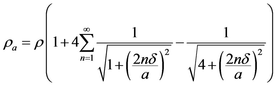 (12)
(12)
where d : first layer depth; r : ground resistivity W×m; a distance between elecrodes
Figure 11 shows the varying of apparent resistivity with frequency. The apparent resistance has no change
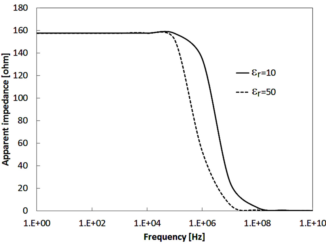
Figure 8. Calculated apparent impedance for er = 10 and 50 and (a = 1 m, r = 1000 Ω×m) vs frequency obtained by four electrodes method.
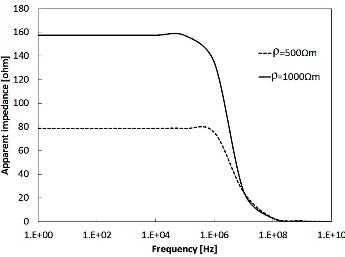
Figure 9. Calculated apparent impedance for r = 500 and 1000 Ω×m and (a = 1 m, er = 10) vs frequency obtained by four electrodes method.
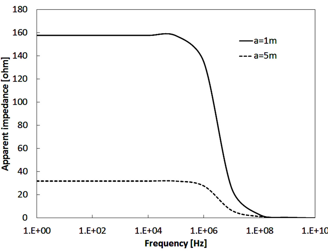
Figure 10. Calculated apparent impedance for a = 1 and 5 m and (r = 1000 Ω×m, er = 10) vs frequency obtained by four electrodes method.
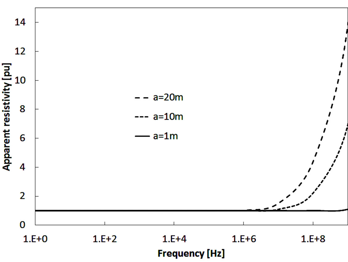
Figure 11. Apparent resistivity vs frequency.
until the frequency reach 1 MHz, after that it is increased as the frequency increases. This increases in apparent resistance due the decrease of the area that the current pass in due to the decrease of penetration depth. The change in apparent resistance increases as the distance between electrodes increases.
The ground capacitive part is frequency dependent by the following equation:
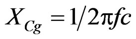 (13)
(13)
In addition of that the penetration affect on the capacitive impedance which can presented as change in penetration depth and apparent relative permittivity as follows:
 (14)
(14)
where d: first layer depth; e: ground relative permittivity, a distance between elecrodes From Equation (14), as the frequency increases, the penetration depth decreases and apparent permittivity decreases.
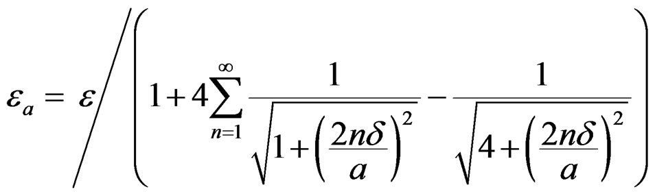
The apparent relative permitivity pu calculated from 4 electrodes buried in homogenous ground with taking into account the effect of penetration depth is assumed to be as follows.
Figure 12 shows the varying of apparent ground relative permittivity (pu) with frequency. The apparent relative permittivity has no change at low frequencies. At high frequency above 1 MHz, the ground relative permittivity (pu) decreases as the frequency increases. This decrease in ground apparent relative permittivity is coming from the decrease of the area that the current pass in due to the decrease of penetration depth.
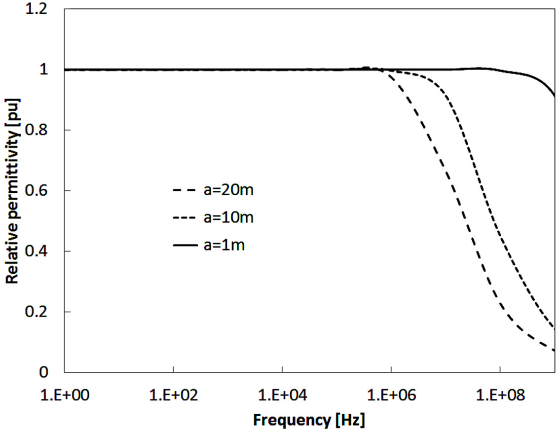
Figure 12. Apparent relative permitivity vs frequency.
5. Conclusion
The four-electrode method is used successfully to measure the ground resistivity and permittivity by injecting a step like current into ground. The balanced transformer is used to solve the problem of charge/discharge cable as source. The measured results show the effects of frequency dependence on ground resistivity. The penetration depth effects on the measured results and can be considered by the proposed equations to estimate the ground resistivity and permittivity. The proposed calculation model proves physically the ground resistivity effects and penetration depth effects on the measured results. The charge simulation method is used successfully in a resistive/capacitive problem at high frequency. The proposed calculation model results agree successfully with the measured results. The apparent ground resistivity increases as the frequency increases. The apparent ground permittivity decreases as the frequency increases.
REFERENCES
- IEEE Power & Energy Society, “IEEE Draft Guide for Measuring Earth Resistivity, Ground Impedance, and Earth Surface Potentials of a Grounding System,” IEEE Standards 81-1983, 2012.
- N. M. Nor, A. Haddad and H. Griffiths, “Performance of Earthing Systems of Low Resistivity Soils,” IEEE Transactions on Power Delivery, Vol. 21, No. 4, 2006, pp. 2039-2047. doi:10.1109/TPWRD.2006.874656
- B. Anggoro, N. I. Sinisuka and P. M. Pakpahan, “Resistivity and Dielectric Constant Characteristic of Soil If are Treated by Water, Salt and Carbon,” 8th International Conference on Properties and Applications of Dielectric Materials, Bali, June 2006, pp. 893-896.
- S. Visacro and R. Alipio, “Frequency Dependence of Soil Parameters: Experimental Results, Predicting Formula and Influence on the Lightning Response of Grounding Electrodes,” IEEE Transactions on Power Delivery, Vol. 27, No. 2, 2012, pp. 927-935. doi:10.1109/TPWRD.2011.2179070
- A. G. Pedrosa, M. A. O. Shroeder, M. M. Afonso, R. S. Alípio, S. de Castro Assis, T. A. S. Oliveira and A. R. Braga, “Transient Response of Grounding Electrodes for the Frequency-Dependence of Soil Parameters,” 2010 IEEE/PES Transmission and Distribution Conference and Exposition: Latin America (T&D-LA), Sao Paulo, 8-10 November 2010, pp. 839-845.
- I. F. Gonos, A. X. Moronis and I. A. Stathopulos, “Variation of Soil Resistivity and Ground Resistance during the Year,” 28th International Conference on Lightning Protection, Kanazawa, 17-21 September 2006, pp. 740-744.
- IEEE Power & Energy Society, “IEEE Guide for Safety in AC Substation Grounding,” ANSI/IEEE Standard 80- 2000, 2000.
- F. Kraus, “Electromagnetics with Applications,” 5th Edition, McGraw-Hill, New York, 1999.
- M. Nayel, “Investigation of Wave Propagation Penetration Depth in Multi-Layer Ground,” IEEJ Transactions on Power and Energy, Vol. 132, No. 8, 2012, pp. 1-6. doi:10.1541/ieejpes.132.728