Journal of Electromagnetic Analysis and Applications
Vol.6 No.3(2014), Article ID:43230,4 pages DOI:10.4236/jemaa.2014.63006
Rectangular Microstrip Patch Antenna Using Air as Substrate for S-Band Communication
1Department of EECE, ITM University, Gurgaon, India, 2Departmentof Electrical and Electronics Engineering, ITM University, Gurgaon & Raipur, India, 3Departmentof Mechanical Engineering, Shinas College of Technology, Shinas, Oman.
Email: manish911989@gmail.com, saurabhsachdeva@itmindia.edu, nkumarswamy15@gmail.com, ipsinghphys@gmail.com
Copyright © 2014 Manish Gupta et al. This is an open access article distributed under the Creative Commons Attribution License, which permits unrestricted use, distribution, and reproduction in any medium, provided the original work is properly cited. In accordance of the Creative Commons Attribution License all Copyrights © 2014 are reserved for SCIRP and the owner of the intellectual property Manish Gupta et al. All Copyright © 2014 are guarded by law and by SCIRP as a guardian.
Received April 21st, 2013; revised December 21st, 2013; accepted January 10th, 2014
Keywords: Rectangular Microstrip Patch Antenna; Air Substrate; Directivity
ABSTRACT
A Rectangular Microstrip Patch Antenna model is proposed using air as a substrate to study the characteristics of designed antenna. The dimensions of designed antenna are 17 mm × 16.66 mm with substrate at frequency 3.525 GHz. In this paper, the simulation is performed by using software Computer Simulation Technology (CST) Microwave studio based on finite difference time domain technique. The characterization of the designed antenna was analyzed in terms of return loss, bandwidth, directivity, gain, radiation pattern, VSWR.
1. Introduction
Due to attractive and unique properties (e.g. low profile, conformal nature, and high speed), microstrip antennas are finding many applications in various fields like Microwave Engineering, Mobile Communication, Satellite Communication and aircraft systems. As a result, in recent years a considerable attention has been paid by many antenna designers to enhance the characteristics of these antennas. Microstrip patch antenna is special class of microstrip antennas. It consists of a patch on one side of a dielectric substrate and ground plane on the other side of the substrate [1]. The patch may be of any geometry like circular, triangular, rectangular, elliptical, square, and ring.
To meet the requirement of low profiling, conformal nature there are numerous materials used as a substrate like RT Duriod 5880, FR4, Alumina, Honeycomb, etc. [2].
Chandra et al. [3] proposed rectangular patch antenna using air as substrate for X-band. They used Agilent’s E8363B network analyzer to obtain simulation results; from simulation results they observed 2 - 3 dB improvement in peak gain. Recently Ali et al. [4] designed the microstrip antenna using the same above substrate at 5.8 GHz frequency; results obtained by them strongly match with Chandra et al. [3].
In this paper a sincere attempt is made to design, model, optimize, and analysis rectangular microstrip patch antenna taking air as a substrate at 3.525 GHz with the help of CST microwave [5] electromagnetic simulator.
2. Antenna Design
The selected dielectric materials for the antenna is air which has a dielectric constant of 1  and the height of dielectric substrate is 1.5 mm (h). We use CST microwave studio for design, modeling of proposed antenna. Microstrip feed line of 50 is used to feed the antenna.
The physical dimensions of the patch are based on the following formulae.
 (1)
(1)
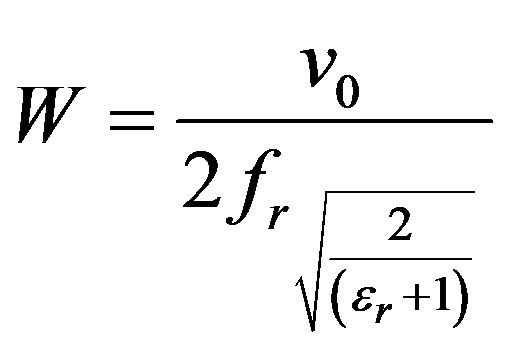 (2)
(2)
where L is the length, W is the width and  is frequency of the proposed antenna.
  is the space speed of light and
  is relative permitivity of substrate. The physical dimensions of the ground plane are based on the following formulae.
 (3)
(3)
 (4)
(4)
where Lg and Wg are the length and width of the ground plane and h is the thickness of substrate. The geometry of proposed antenna is shown in Figure 1. The dimension is taken in millimeters (mm) and numbers of used mesh cells are 28,899.
3. Optimized Antenna Design
The dimensions of the metallic patch were slightly changed in order to improve the antenna performance parameters. A systematic study of thickness of the substrate is optimized from 0.2 mm to 4.4 mm in 0.1 mm increments. Finally the dimension of ground plane is mm and dimension of the patch is 17 mm × 16.66 mm.
4. Simulation Results
The measured and simulated results obtained for proposed antenna are presented graphically and numerically. CST microwave studio [5] electromagnetic simulator has been used to obtain these results.
4.1. Return Loss
Return Loss is a measurement from which we can judge how much amount of power is reflected back by the antenna.
The numerical value of the S11 parameter from the Figure 2 is −40.9638 dB. There is one sharp narrow deep at 3.525 GHz which shows that proposed antenna is a single band antenna. The bandwidth of the proposed antenna is found to be 140.6 MHz from Figure 2.
4.2. Radiation Pattern
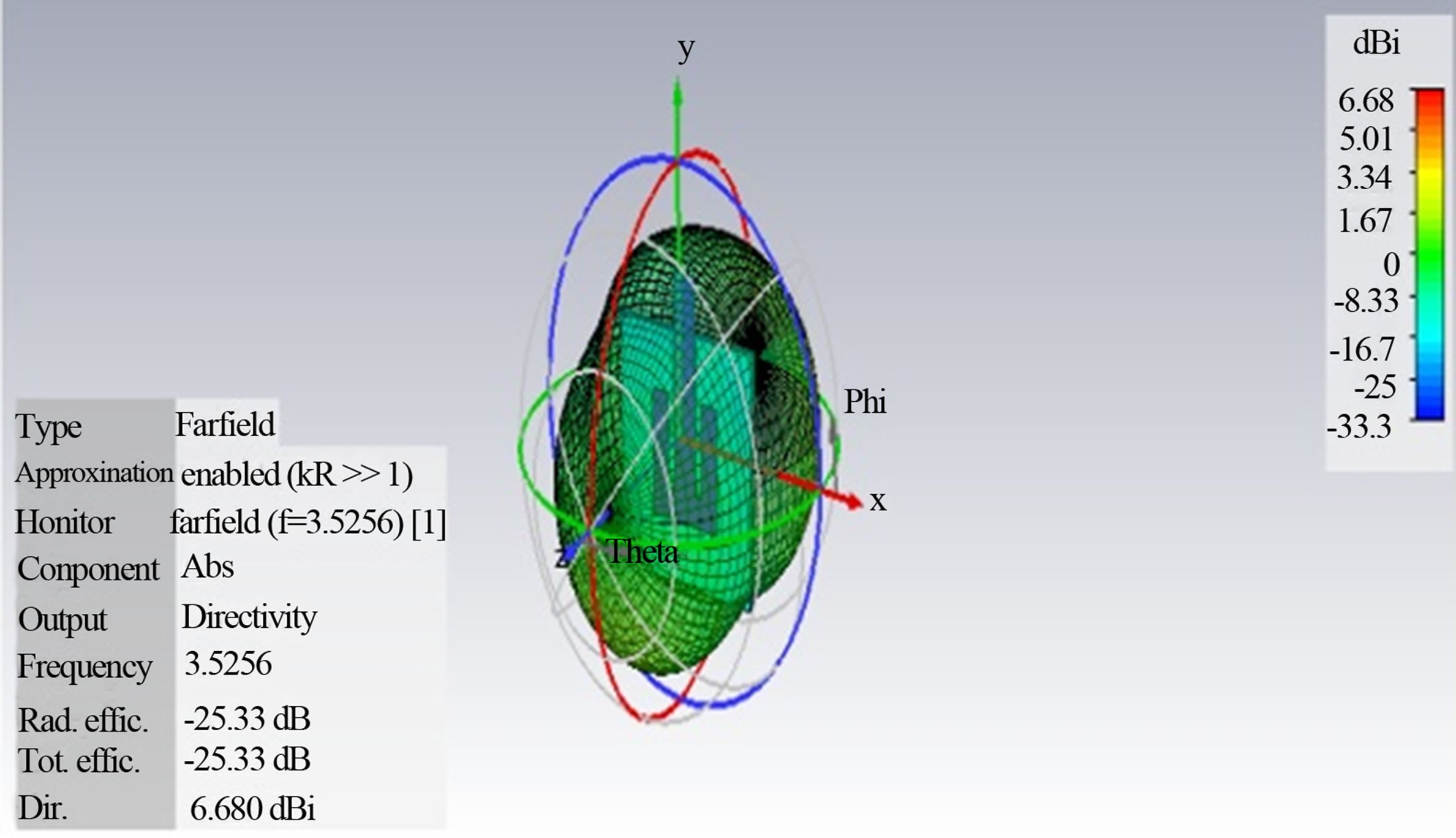
It is a graphical representation of the radiation properties of the antenna as a function of space coordinates [2]. Here the radiation pattern is determined in the far field region.
In this paper we only discuss two radiation properties namely directivity and polarization. Figures 3(a)-(d), are the 3D, 2D, polar and Cartesian graphs of the radiation pattern respectively. Figure 3(a) shows that the directivity of the proposed antenna is 6.68 dBi, radiation efficiency is −25.33% and total efficiency is −25.33%. It is also observed that maximum radiation is emitting from the center of the top the patch. This shows that the proposed antenna is feasible for S-band communication. From Figure3(c) an angular width (3dB) of antenna is 71.0 deg.
4.3. VSWR
VSWR is the way to see how much system is matched. It is the ratio between the maximum voltage and minimum voltage in the transmission line. For the best value of antenna it should be equal to 1.
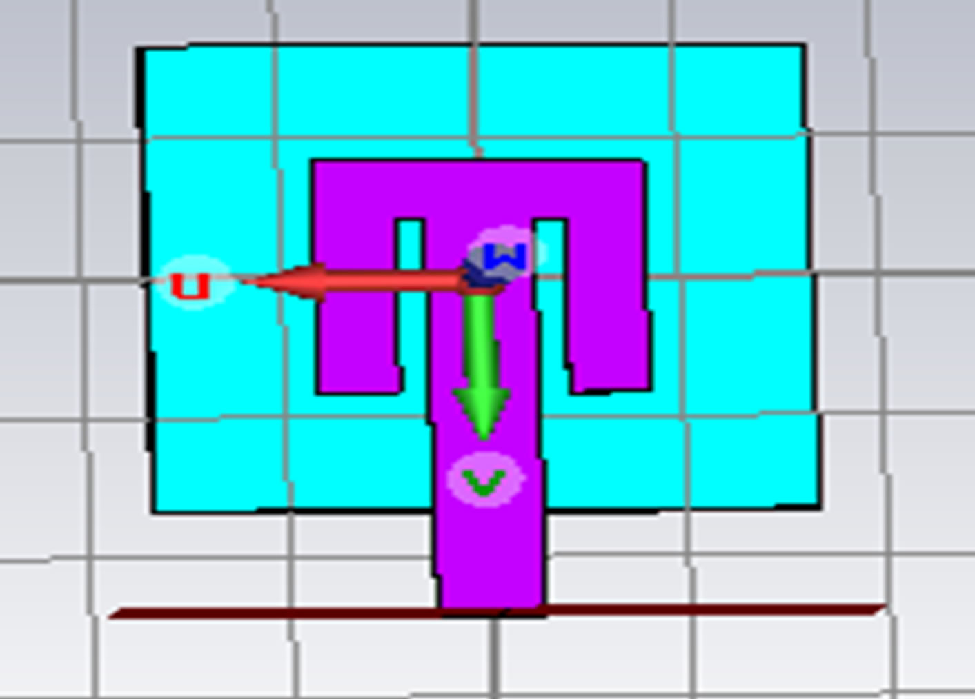
Figure 1. Geometry of proposed antenna operating at 3.525 GHz.
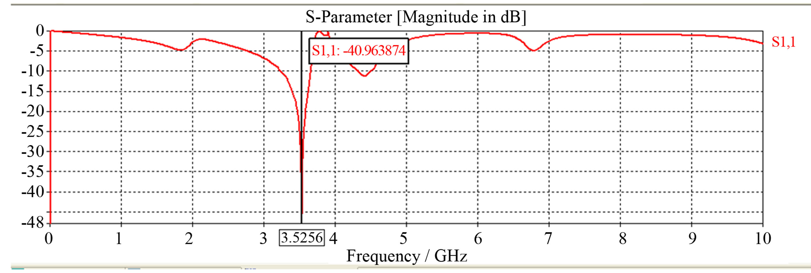
Figure 2. Return loss of purposed antenna at 3.525 GHz.
 (a)
(a)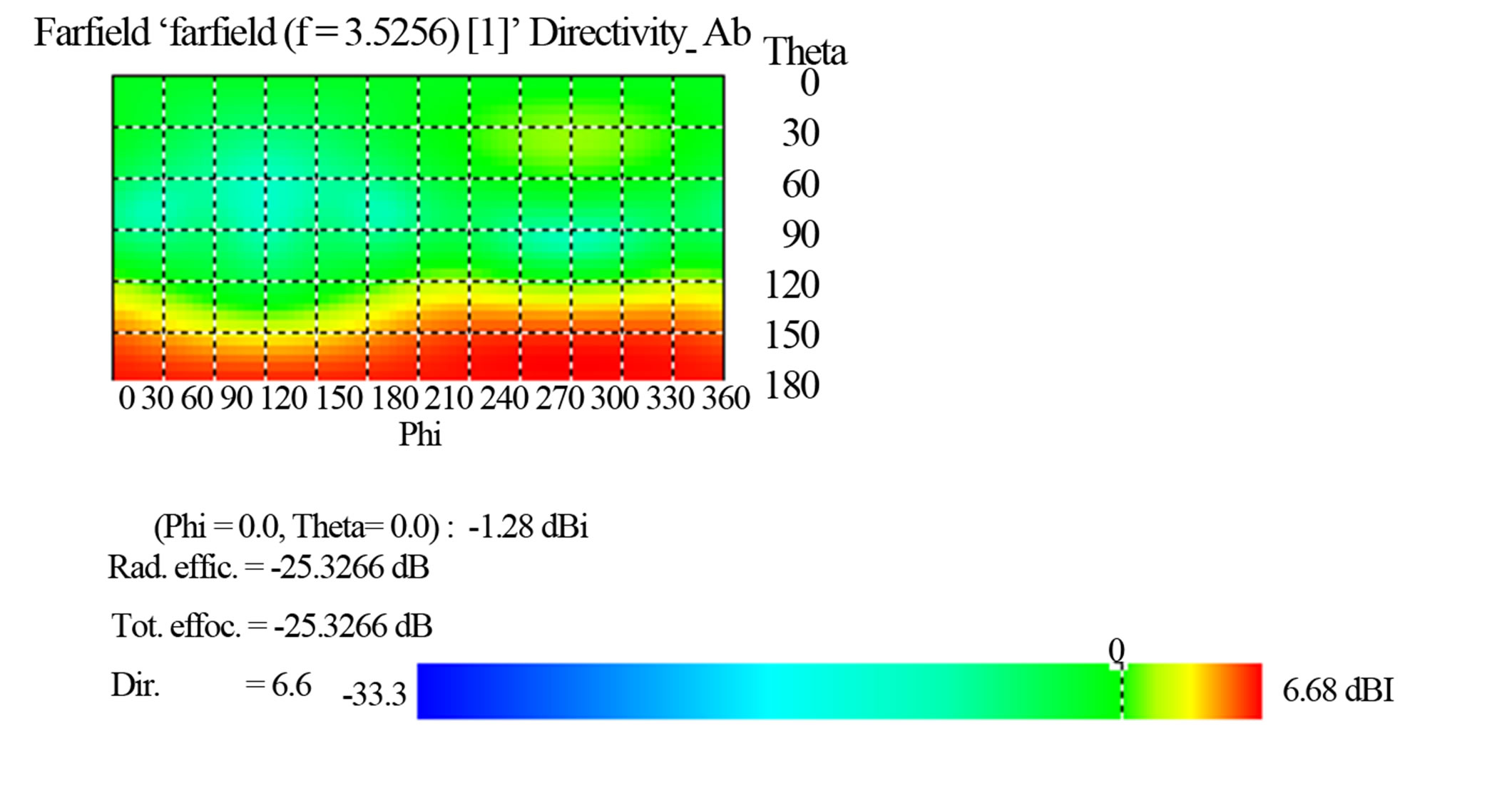 (b)
(b) (c)
(c)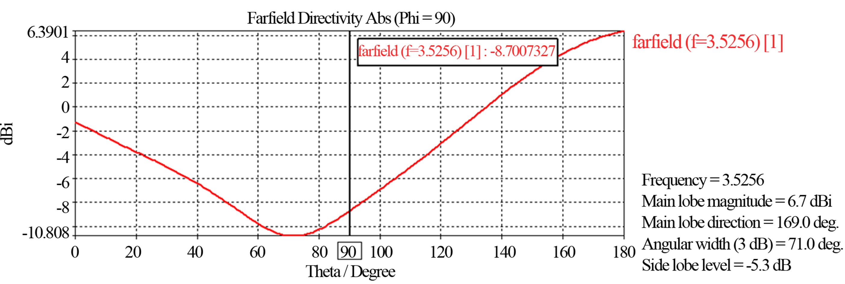 (d)
(d)
Figure 3. (a) 3D-Radiation pattern of proposed antenna at 3.525 GHz. (b) 2D-Radiation pattern of proposed antenna at 3.525 GHz. (c) Polar plot of proposed antenna operating at 3.525 GHz. (d) Cartesian plot of proposed antenna operating at 3.525 GHz .
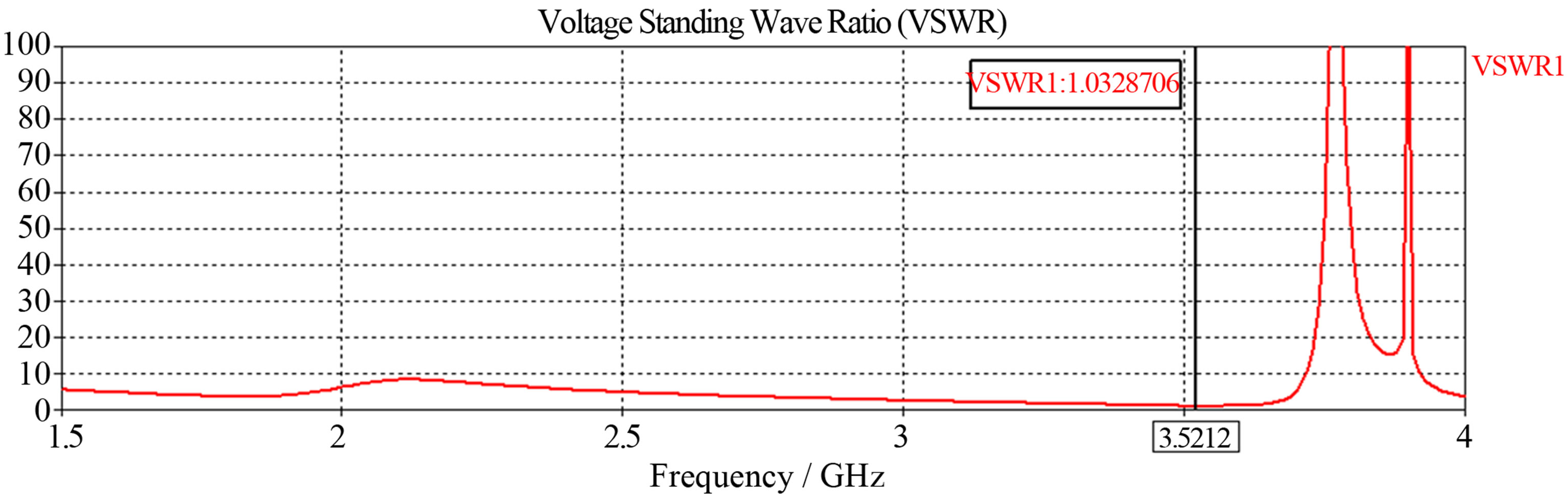
Figure 4. VSWR plot of proposed antenna operating at 3.52 GHz.
Looking at Figure 4, it can be observed that the measured value of VSWR is 1.0328.
5. Conclusion
This paper has successfully designed a rectangular patch antenna operating at 3.525 GHz. It is found that using air as a substrate has been an improvement in return loss of −40.965 dB. The antenna also is capable of functioning at 3.525 GHz with a gain of 6.68 dBi. This antenna has a big potential for a Microwave application.
Acknowledgements
Authors are thankful to reviewer for their helpful comments.
REFERENCES
- K. F. Lee and K. M. Luk, “Microstrip Patch Antennas,” Imperial College Press, London, 2011.
- C. A. Balanis, “Antenna Theory,” 2nd Edition, John Wiley & Sons, Inc., 1997.
- C. Chandan, A Ghosh, S. K. Ghosh and S. Chattopadhyay, “Radiation Characteristics of Rectangular Patch Antenna Using Air Substrates,” 2009 International Conference on Emerging Trends in Electronic and Photonic Devices & Systems, Varanasi, 22-24 December 2009, pp. 346-348.
- M. T. Ali, “Gain Enhancement of Air Substrates at 5.8 GHz for Microstrip Antenna Array,” Microwave Technology Centre (MTC), Univ. Teknol. MARA (UiTM), Shah Alam, 2012, pp.477-480.
- CST Microwave Studio, “CSTGmbh-Computer Simulation Technology,” 2012.