Journal of Electromagnetic Analysis and Applications
Vol. 5 No. 4 (2013) , Article ID: 29659 , 6 pages DOI:10.4236/jemaa.2013.54023
Effect of Battery on Moving Properties of Cableless In-Piping Magnetic Actuator
![]()
Faculty of Engineering, Tohoku Gakuin University, Tagajo, Japan.
Email: yaguchi@tjcc.tohoku-gakuin.ac.jp
Copyright © 2013 Ryuichi Watanabe et al. This is an open access article distributed under the Creative Commons Attribution License, which permits unrestricted use, distribution, and reproduction in any medium, provided the original work is properly cited.
Received January 24th, 2013; revised February 23rd, 2013; accepted March 10th, 2013
Keywords: Cableless Magnetic Actuator; Pipe inside Mover; Propulsion Module; Vibration; Electrical DC-AC Inverter
ABSTRACT
This paper proposes a cableless in-piping magnetic actuator that exhibits a very high-speed locomotion into inner pipe of 8 mm. The cableless magnetic actuator is moved according to the vibration amplitude and resonance energy of a mass-spring system excited by using an electromagnetic force. The iron core size of the bobbin type electromagnet was roughly designed by computer simulation and then optimized experimentally. The proposed actuator incorporates an electrical inverter that directly transforms DC from button batteries into AC. The electrical DC-AC inverter incorporates a mass-spring system, a reed switch and a curved permanent magnet that switch under an electromagnetic force. The duty ratio is changed into this electrical inverter by changing the position of the curved magnet and the reed switch. Experimental result demonstrates that the cableless magnetic actuator was able to move horizontally at 471 m, and horizontal speed at 327 mm/s when Maxell SR621W silver-oxide button batteries were used.
1. Introduction
There is the need of the robot which transports a very small amount of medicine and bacteria from a laboratory to a laboratory in the same building or another building. In consideration of safety, the transportation system expects interception with the outside air. Furthermore, the realization for in-piping robots capable of high speed locomotion over long-range inside a thin pipes is required because of setting of the big pipe is unfavorable in security. A number of studies have investigated the mechanisms of an actuator controlled through an electric cable to provide locomotion in a pipe using devices such as piezoelectric elements [1,2], shape memory alloys [3,4], and electromagnetic motors [5-10]. However, little research has been conducted on cableless robots [11-14] and electromagnetic vibration type [15-18] proposed by authors. In the case of cableless robots, cableless actuators are not capable of movement over long distances. There are several design problems with regard to extending the range and avoiding tangling of cables when the actuator moves a long-range movement. As such, a cableless system is clearly desirable. However, a cableless actuator having a range of movement over several hundred meters in a thin pipe with a diameter of several millimeters has not yet been reported.
The authors previously proposed [16-18] a novel cableless actuator that provides propulsion by a new motion principle that combines mechanical vibration and electromagnetic force. However, the moving properties by effect of loaded battery are not completely investigated.
The present study is to completely investigate the moving characteristics of the cableless magnetic actuator presented in the previous paper [16-18]. The effect of the two kinds of batteries on the moving properties of the cableless actuator was discussed. Influence of the duty factor of the electrical DC-AC inverter on the moving properties of the actuator was demonstrated. In addition, experimental results demonstrate that the moving properties of the actuator by the change of the shape of the electromagnet were improved in comparison with a previous paper [16,18]. The results are promising for the creation of highly mobile actuators capable of movement in pipes having diameters of less than 10 mm.
2. Structure of Cableless Magnetic Actuator
Figures 1(a) and (b) show a schematic diagram of the proposed cableless magnetic actuator, which is capable of
 (a)
(a) (b)
(b)
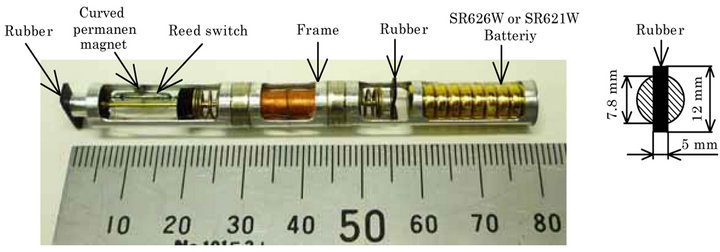
Figure 1. Cableless magnetic actuator. (a) Structure of the cableless magnetic actuator; (b) Cableless magnetic actuator inserted in pipe.
moving within a pipe having an inner diameter of 8 mm. The magnetic actuator consists of a propulsion module, an electrical DC-AC inverter composed of a reed switch, a curved permanent magnet, a frame, and a number of button batteries. In the present paper, two actuators with different propulsion modules, referred to as modules I and II were investigated. The dimension of the magnet of propulsion module I is different as compared with that of the previous study [18] for the purpose of improving properties of movement. Figure 2(a) illustrates detail of the propulsion module I. The propulsion module I is composed of two identical ring type permanent magnets, labeled A and B, two translational springs, two metallic rods with plastic circular plates of ring type, and a bobbin type electromagnet. Module II is identical to module I except that module II has no permanent magnet B. In module I, the axial magnetic field of the electromagnet is used more effectively compared with module II. Permanent magnet A is a NdFeB magnet and is magnetized in the axial direction. Permanent magnet A has an outer diameter of 7.8 mm, an inner diameter of 5.5 mm, and a thickness of 2.5 mm. Permanent magnet B is a NdFeB magnet and is magnetized in the axial direction. Permanent magnet B has an outer diameter of 6.5 mm, an inner diameter of 2 mm, and a thickness of 1.5 mm. The surface magnetic flux density measured using a tesla meter is 265 mT for permanent magnet A and 225 mT for permanent magnet B. The two identical translational springs are stainless steel compression coil type springs and have an outer diameter of 6 mm, a free length of 5 mm, and a spring constant of  . To obtain the optimal moving characteristic, the optimal spring constant appropriate for the magnetic circuit was chosen. As shown in Figure 2(b), the bobbin type electromagnet consists of an iron core with 3150 turns of 0.07-mm-diameter copper wire. The iron core with a circular plate of thicknesses

Figure 2. Propulsion module I of the actuator.
H = 1 mm and diameters D = 5 mm was used in the present study. The size of the iron core is different as compared with that of the previous study [16,18]. The electrical resistance of the electromagnet is 223 W. In combination with the two translational springs, this electromagnet also acts as the mass of the mass-spring system.
As shown in Figure 2, the spring is adhered to the ring type plastic plate, and the electromagnet and the two springs are connected by two metallic rods with metallic circular plates at both ends. The legs used to support the actuator are constructed of natural rubber having a total length of 10 mm, a thickness of 0.5 mm, and a width of 5 mm. The rubber legs are attached to the electromagnet by means of a square plastic rod of 5 mm in length and a metallic rod. The electromagnet and the two rubber legs move in unison. Figure 1(a) also illustrates an electrical DC-AC inverter, which was developed in order to realize a cableless actuator. This inverter is composed of a reed switch and a curved permanent magnet. The reed switch has a diameter of 1.8 mm and a length of 10 mm. The actuator containing 10 button batteries of SR626W silver-oxide has a length of 80 mm and a total mass of 9.8 g.
On the other hand, the actuator with 10 button batteries of SR621W silver-oxide is a length of 75 mm and a total mass of 8.8 g.
The actuator is able to move by the difference in frictional force between forward and backward supporting force of flexible materials like a rubber [16-18].
3. Propulsion Properties of the Magnetic Circuit
Figure 3 shows a sectional view of a bobbin type electromagnet of the propulsion module. The iron core of the bobbin type electromagnet consists of two identical circular plates, and a straight rod of 2.7 mm in diameter. The iron core of the bobbin type electromagnet was roughly designed by computer simulation and then opti mized experimentally. As shown in Figure 2(b), the iron core has a circular plate with H = 1 mm and D = 5 mm.
An experiment was conducted using the apparatus shown in Figure 4. A direct current by using several button batteries was applied to the electromagnet during measurement. The origin of the measurement was taken
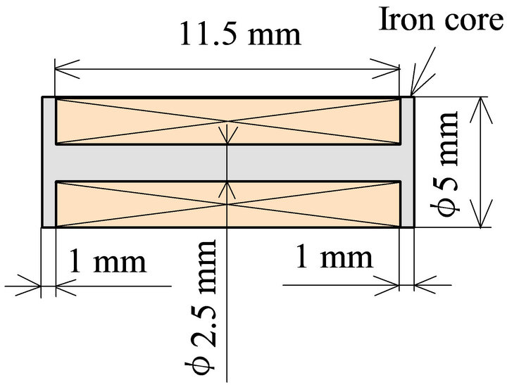
Figure 3. Bobbin type electromagnet.
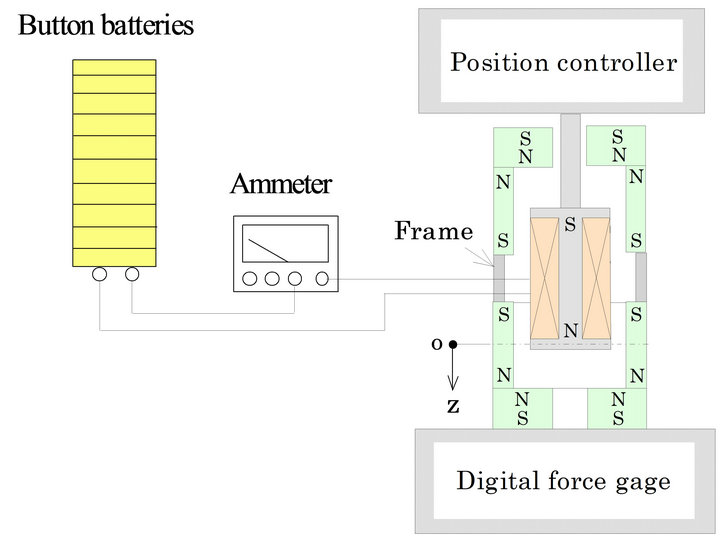
Figure 4. Relationship between the position z and the magnetic static force.
as center of the ring type permanent magnet, and the z position was measured as shown in Figure 4.
Figure 5 shows the relationship between the number of the batteries and the maximum magnetic static force for propulsion modules I and II. The magnetic static force becomes maximum when the z position is zero. Both curves increase linearly with the number of batteries. In the present study, Maxell SR626W silver-oxide button batteries were used. Each battery is 6.8 mm in diameter and 2.6 mm thick and has a mass of 0.4 g and a capacity of 28 mAh at a nominal output of 1.55 V.
Figure 6 shows the relationship between the displacement of the spring and the force. When using of the propulsion module to produce a large force, the influence of the nonlinearity of the spring increases considerably. When the nonlinearities of the spring increase, the vibration displacement of the actuator becomes the small. We have to reduce the nonlinearity of the spring, and measures to increase the force will be necessary in future.
4. Structure and Operating Principles of the Electrical DC-AC Inverter
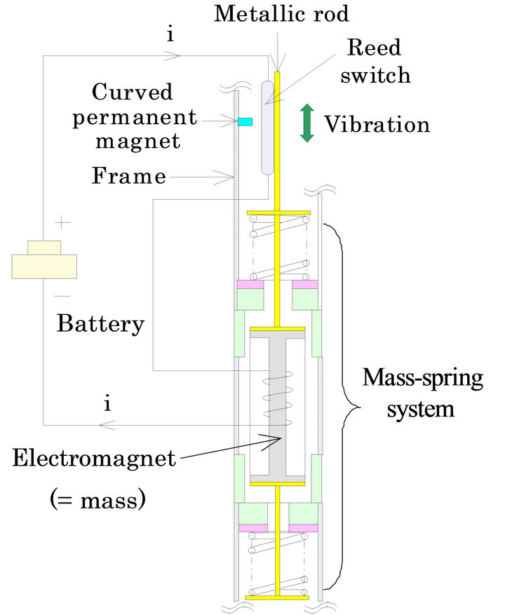
Figure 7 shows a diagram of the electrical DC-AC inverter for the realization of a cableless actuator. The structure and size of the electrical DC-AC inverter are the same as previous study [16-18]. As mentioned earlier, the proposed inverter is composed of a reed switch and a curved permanent magnet. The reed switch is 1.8 mm in
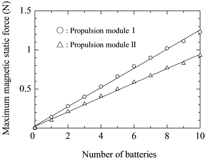
Figure 5. Relationship between number of battery and maximum magnetic static force.
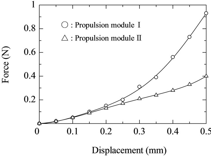
Figure 6. Relationship between position z and force.
diameter and has a length of 10 mm. The curved permanent magnet is an arc type NdFeB magnet having a width of 1 mm and a thickness of 0.8 mm and is magnetized in the axial direction. The reed switch and the bobbin type electromagnet are connected by thin copper wire to a DC source, such as a battery, as shown in Figure 7(a). The reed switch attached to the electromagnet vibrates around the curved permanent magnet. The strength of the magnetic field between the curved permanent magnet and the reed switch attached to the electromagnet is determined by the vibration amplitude. The mass-spring system vibrates, and the two cantilever beams inserted into the body of the reed switch make and break contact, cycling the switch on and off. As a result, the DC voltage is converted into a square alternating waveform, and the magnetic force acts on the mass-spring system.
The direct current into the electromagnet was 0.05 A. The current waveform generated during switching of the reed switch was stored in a PC via a fast Fourier transform (FFT) analyzer. Figures 7(b) and (c) show the arrangement of the reed switch and the curved permanent magnet. The origin of the measurement was taken as the center of the curved permanent magnet, the x and z coordinates were measured as shown in Figure 7(c).
 (a)
(a)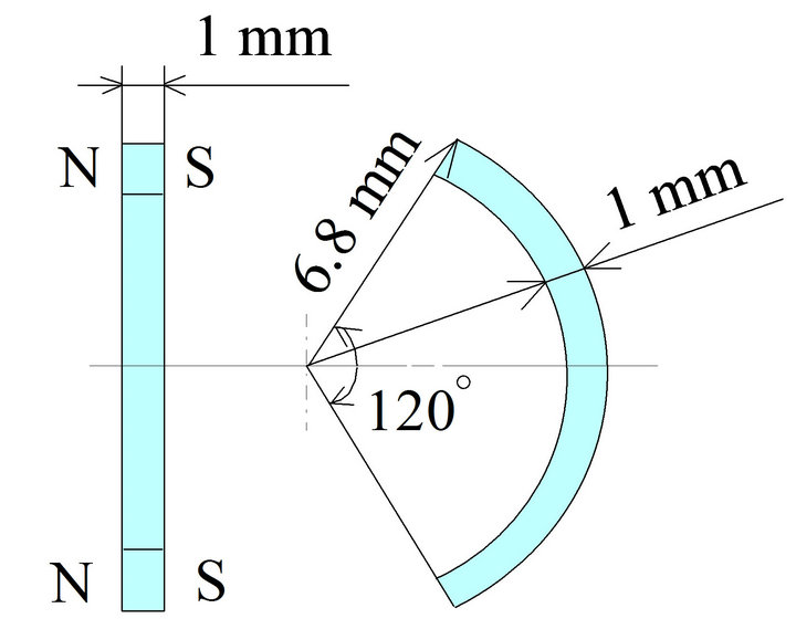 (b)
(b) (c)
(c)
Figure 7. Principle of the electrical DC-AC inverter composed of a reed switch and a curved permanent magnet. (a) Principle of the DC-AC inverter; (b) Curved permanent magnet; (c) Reed switch.
Figure 8 shows the displacement of the mass-spring system and the current generated due to the reed switch and the curved magnet when the position x and z was 0.2 mm and 0.3 mm. The duty factor of the current produced at this time was about 40%.
Figure 9 shows the relationship between the duty factor and the position z when the position z was taken to 0.2 mm.
When the interval during the position z and the origin spreads, the duty factor becomes small.
5. Locomotion Characteristics of the Cableless Magnetic Actuator
Maxell SR626W silver-oxide button batteries or Maxell
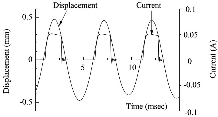
Figure 8. Displacement and waveform of the current produced by the DC-AC inverter.
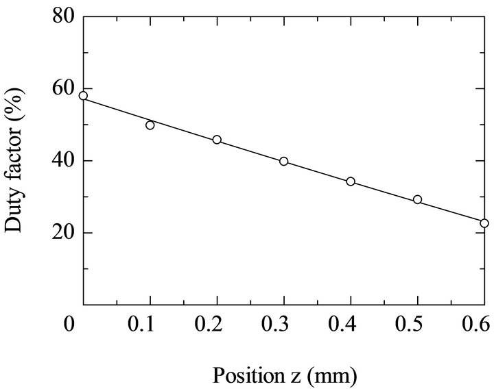
Figure 9. Relationship between the position z and the duty factor.
SR621W silver-oxide button batteries as the power source for the actuator were used. The battery of SR621W is 6.8 mm in diameter and 2.15 mm thick, with a mass of 0.3 g and a capacity of 18 mAh at a nominal output of 1.55 V. In all measurements, the supporting force of the actuator in the pipe was set to 0.12 N.
Figure 10 shows the relationship between the duty factor and the vertical upward speed of the actuator with propulsion modules I when Maxell SR626W button battery pack was used.
Thus, vertical upward speed of the actuator can change by changing the duty factor of the electrical DC-AC inverter.
Figure 11 shows the relationship between the duty factor and self-propellant efficiency of the actuator for eight and ten SR626W batteries. The self-propellant efficiency η is expressed as follows:
 (1)
(1)
where vup is the vertical speed, M is the total mass of the actuator, G is the acceleration due to gravity, V is the input voltage, and I is the input current. The maximum efficiency of the actuator for ten SR626W batteries is 56% when the duty factor was 20%. The efficiency is
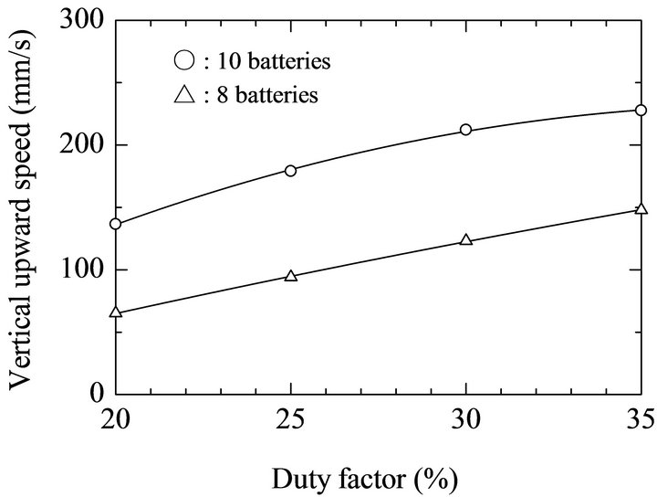
Figure 10. Relationship between duty factor and vertical upward speed.
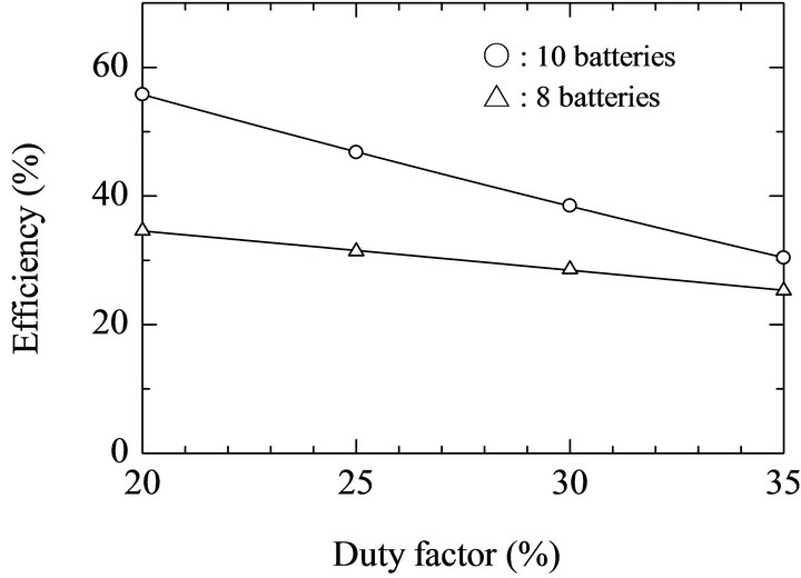
Figure 11. Relationship between duty factor and efficiency.
thought to be high for an electromagnetic actuator of this size.
The solid line in Figure 12 shows the relationship between the number of button batteries and the vertical upward speed of the actuator with propulsion modules I or II. The position x between the reed switch and the curved magnet is 0.2 mm, and the position z is 0.5 mm. The duty factor at this time was 35%. The increase in the static magnetic force brings increase in speed when Maxell SR626W silver-oxide button batteries were used. For the case of ten batteries, the vertical speed was  . It can be seen that the maximum vertical upward speed in the present study slightly increased than that of previous study obtained [18] by changing size of the iron core. In this figure, the broken line shows the result when Maxell SR621W silver-oxide button batteries were used. For the case of ten batteries, the vertical speed was 242 mm/s. This is because the mass of the SR621 battery is lighter than that of SR626 battery. In the case of a lightweight actuator, because frequency of the actuator increases, high speed locomotion is possible. The vertical upward speed was 29 mm/s when SR621W four batteries were used. The actuator of this case is a length of 62 mm and a total mass of 7 g. By the change of the shape of the electromagnet, the moving properties of the actuator were improved in comparison with a previous paper [16,18]. The moving property of this cableless

Figure 12. Relationship between number of batteries and vertical upward speed.
magnetic actuator exhibits good performance compared with other types of actuators that are powered by an electric cable [1-10].
On the other hand, for the case of SR621W ten batteries, the horizontal speed was 327 mm/s. The total range of this actuator was 471 m in for horizontal motion over 24 minutes. The horizontal speed was 298 mm/s when Maxell SR626W button batteries were used. The total range of this time was 679 m in for horizontal motion over 38 minutes.
6. Conclusion
A cableless magnetic actuator powered by an electrical DC-AC inverter capable of locomotion in a thin pipe has been proposed and tested. The difference of the two kinds of batteries on the moving properties was discussed. The actuator was able to move horizontally at 327 mm/s, and vertical upward at 242 mm/s when Maxell SR621W silver-oxide button batteries were used. Thus, the proposed actuator is highly promising for transportation of straight piping systems. Experimental result demonstrates that the speed of the cableless magnetic actuator is able to change by changing the duty factor of the electrical DC-AC inverter. In addition, we demonstrated that the efficiency improved by the changing the duty factor. When using of the magnetic circuit to produce a large magnetic force, the nonlinearities of the spring increase. Accordingly, if the magnetic circuit to produce appropriate force with light weight was loaded, and frequency of the actuator can increase, the moving properties of the magnetic actuator considerably improve.
7. Acknowledgements
The authors would like to thank K. Ishikawa of the Tohoku Gakuin University.
REFERENCES
- H. Saito, K. Sato, K. Kudo and K. Sato, “Fundamental Study of Mover Travel Inside a Small Diameter Pipe,” Transactions of the Japan Society of Mechanical Engineers, Vol. 66, No. 641, 2000, pp. 346-353. doi:10.1299/kikaic.66.346
- J. Fujita, Y. Shiraogawa, S. Yamamoto and T. Kato, “Study of Mobile Mechanism with Elastic Fibers by Using Vibration,” Transactions of the Japan Society of Mechanical Engineers, Vol. 70, No. 698, 2004, pp. 22-26.
- J. Kwon, S. Park, B. Kim and J. Park, “Bio-Material Property Measurement System for Locomotive Mechanism in Gastro-Intestinal Tract,” Proceedings of IEEE International Conference on Robotics and Automation, Barcelona, 18-22 April 2005, pp. 1315-1320.
- D. Reynaerts, J. Peilw and H. Brussel, “Design of a Shape Memory Actuated Gastrointestinal Intervention System,” Proceedings of Actuator 96, 1996.
- S. Guo and Q. Pan, “A Paddling Type of Microrobot in Pipe,” Proceedings of IEEE/RSJ International Conference on Intelligent Robots and Systems, Edmonton, 2-6 August 2005, pp. 2265-2270.
- T. Miyagawa and N. Iwatski, “Moving Characteristics in Bent Pipes of In-Pipe Mobile Robot with Wheel Drive Mechanism Using Planetary Gear Drive,” Journal of the Japan Society for Precision Engineering, Vol. 74, No. 12, 2008, pp. 1346-1350.
- J. Bocko, M. Kelemen, T. Kelemenova and J. Jezny, “Wheeled Locomotion inside Pipe,” Bulletin of Applied Mechanics, Vol. 5, No. 18, 2009, pp. 34-36.
- H. Choi and S. Roh, “In-Pipe Robot with Active Steering Capability for Moving inside of Pipelines,” Bioinspiration and Robotics Walking and Climbing Robots, Vol. 23, 2007, pp. 375-400.
- K. Suzumori, S. Wakimoto and M. Tanaka, “In Pipe Inspection Micro Robot Adaptable to Changes in Pipe Diameter,” Proceedings of IEEE International Conference on Robotics and Automation, Taipei, 14-19 September 2003, pp. 2735-2740.
- I. Brunete, J. Torres, M. Hernando and E. Gambao, “A 2 DoF Servomotor-Based Module for Pipe Inspection Modular Micro-Robots,” Proceedings of International Conference on Intelligent Robots and Systems, Beijing, 9-15 October 2006.
- T. Fukuda, H. Hosoi and H. Ohyama, “A Study on InPipe Inspection Robots,” Transactions of the Japan Society of Mechanical Engineers, Vol. 57, No. 537, 1991, pp. 243-248.
- K. Tsuruta, T. Shibata, N. Mitsumoto, T. Sasaya and M. Kawahara, “Compact and Low Power Consumed Control Circuit for Wireless Micromachine,” Transactions of the Institute of Electric Engineers of Japan, Vol. 122, No. 2, 2002, pp. 67-72.
- A. Chiba, M. Sendoh, K. Ishiyama, K. Arai, H. Kawano1, A. Uchiyama1 and H. Takizawa, “Magnetic Actuator for a Capsule Endoscope Navigation System,” Journal of Magnetics, Vol. 12, No. 2, 2007, pp. 89-92. doi:10.4283/JMAG.2007.12.2.089
- H. Yaguchi, N. Sato, A. Shikoda and K. Ishikawa, “Novel Globular Magnetic Actuator Group Capable of Free Movement in a Complex Pipe,” Journal of Electromagnetic Analysis and Applications, Vol. 3, No. 9, 2011, pp. 387-393. doi:10.4236/jemaa.2011.39061
- H. Yaguchi and T. Izumikawa, “Performance of Cableless Magnetic In-Piping Actuator Capable of High-Speed Movement by Means of Inertial Force,” Advances in Mechanical Engineering, Vol. 2011, 2011, pp. 1-9, Article ID: 485138.
- T. Izumikawa and H. Yaguchi, “Cableless Magnetic Actuator Capable of High-Speed Movement in Pipe by New Type Propulsion Module,” Advanced Materials Research, Vol. 452-453, 2012, pp. 1252-1256.
- H. Yaguchi and T. Izumikawa, “Cableless Magnetic Actuator Capable of Locomotion in a Thin Pipe by Means of a New Motion Principle,” IEEE Transactions on Magnetics, Vol. 47, No. 10, 2011, pp. 4290-4293. doi:10.1109/TMAG.2011.2151272
- T. Izumikawa and H. Yaguchi, “Movement of a Cableless In-Piping Magnetic Actuator with a New Propulsion Module,” IEEE Transactions on Magnetics, Vol. 48, No. 11, 2012, pp. 4196-4199. doi:10.1109/TMAG.2012.2201919