Journal of Electromagnetic Analysis and Applications
Vol.5 No.2(2013), Article ID:28499,5 pages DOI:10.4236/jemaa.2013.52009
Open Waveguide Based on Low Frequency Spoof Surface Plasmon Polaritons
![]()
1Department of Electrical Engineering, Chung Hua University, Hsinchu, Taiwan; 2College of Engineering, Chung Hua University, Hsinchu, Taiwan; 3Department of Communication Engineering, Chung Hua University, Hsinchu, Taiwan; 4Department of Electronic Engineering, Lunghwa University of Science and Technology, Kueishan, Taiwan.
Email: *jjwu@chu.edu.tw
Received November 28th, 2012; revised December 29th, 2012; accepted January 12th, 2013
Keywords: Metamaterials; Surface Plasmon Polaritons; Band Pass Filter; Waveguides
ABSTRACT
A kind of plasmonic open waveguide, which is a periodic subwavelength metallic Domino array, is investigated both theoretically and experimentally in this paper. Based on the guiding mechanism of spoof surface plasmon polaritions (spoof SPPs), the transmission properties of this waveguide are controllable by altering the geometric parameters of the periodic structure. Microwave experimental results verify the high efficiency of wave guiding in such open waveguide, as predicted in theoretic analysis.
1. Introduction
Surface plasmon polaritons (SPPs) are electromagnetic (EM) excitations propagating along the metal-dielectric interface, whose electromagnetic fields can be strongly confined to the near vicinity of the interface [1]. This confinement leads to an enhancement of the electromagnetic field at the interface, resulting in an extraordinary sensitivity of SPPs to surface conditions. Thus, SPPs provide the possibility of concentrating and channeling light with subwavelength structures, which opens up a previously inaccessible length scale for optical research. It is desired naturally to extend highly localized waveguiding and surface-enhanced effects to terahertz (THz) or microwave regimes. At these low frequencies, however, metals behave no longer like a plasma but resemble a perfect electric conductor (PEC), as their plasma frequencies are often in the ultraviolet part of the EM spectrum, and as a result, SPPs are highly delocalized on metal surfaces. To engineer surface plasmon at lower frequency, it was proposed [2-5] that by cutting holes or grooves on a scale much smaller than the wavelength of probing radiation in metal surfaces to increase the penetration of the fields into the metal, the frequency of existing surface plasmons can be tailored at will [6]. The existence of such geometry-controlled SPPs, named spoof SPPs, has recently been verified experimentally in the microwave regime [7]. Such periodic subwavelength structure with highly confined EM field is investigated in the applications of the THz and microwave waveguide, and has been utilized in the high speed circuit to suppress interference [8,9]. The physical mechanism of such metallic subwavelength periodic grooves is presented in detail in [10]. In this paper, we put forward a microwave metallic open waveguide based on the principle of spoof SPPs constructed by periodic subwavelength Domino structure. Such open waveguide has superior advantage and designing flexibility, on one hand it can easily couple with and support high power guided EM wave, on the other hand, by adjusting the period and height of Domino, we can control the transmission bandwidth, which means this structure can be designed as band pass filter.
2. Numerical Analysis
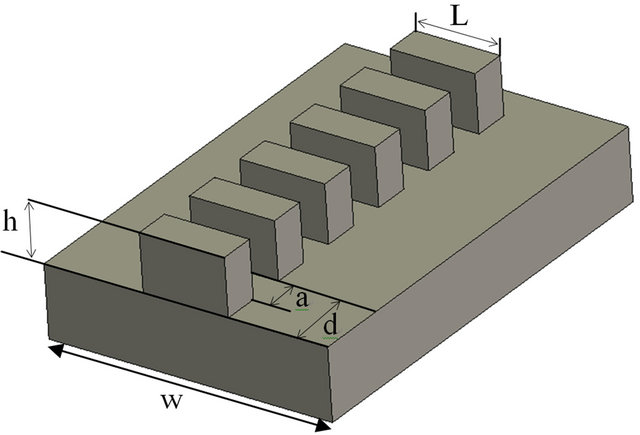
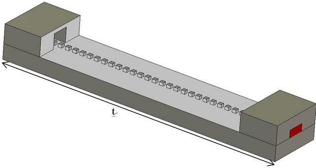
The proposed plasmonic open waveguide is constituted by periodic subwavelength Domino structures, as shown in Figure 1(a), with the height of h, period of d, adjacent interval a and width of L, the metallic base has width w of and length of t. For simplicity, we assume the metal to be perfect electric conductor (PEC) in simulation, which is reasonable approximation in microwave frequency. The plasmonic waveguide is composed by periodic subwavelength Domino structure, the every single space between two adjacent Domino blocks works as a resonator with separate resonant mode. As these resonators line up periodically in series, the resonant mode for every space couples to each other through the mechanism of Block wave, and form a transmission band with guided field near the tight-binding limit. Finite element method is employed in the plasmonic open waveguide simulation of transmission properties, which can provide both the dispersion line and the S parameters, and facilitates the optimization process of the waveguide designing. Figure 1(b) displays the fundamental dispersion line of the plasmonic open waveguide describing the relation between normalized propagation constant β and working frequency, here β is restrict within the first Brillouin zone, i.e., . The geometric parameters are d = 10 mm, a = 0.5d, L = 5 mm, and h equals to 4.0 mm and 6.0 mm respectively for two cases. Our numerical analysis mainly focuses on the fundamental mode of the plasmonic open waveguide, as the EM field is greatly confined near the surface and can be easily excited in X band in experiment. The guided mode is on the right side of the light line represented by dashed red line. When h = 4.0 mm, the cutoff frequency is 9.72 GHz, the asymptotic frequency is 11.505 GHz, and the working frequency band is 1.785 GHz. When h = 6.0 mm, the cutoff frequency is 7.136 GHz, the asymptotic frequency is 8.98 GHz, and the working frequency band is 1.85 GHz. From Figure 1(b), as the height of the Domino structure h increases, the asymptotic frequency decreases, the transmission bandwidth increases and the confinement of the modal field distribution improves. Magnetic field distributions in a unit cell are shown in Figure 1(c) at asymptotic frequency
 , which is 11.505 GHz for the case of h = 4.0 mm, and is 8.98 GHz for the case of h = 6.0 mm. At the asymptotic frequency the structure has the greatest confining capability, and the confining capability improves as the height of the Domino structure increases. The electric field distributions at the asymptotic frequency for the two cases are presented in Figure 1(d).
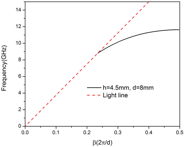
In experiment, the waveguide adaptor we used is in the X band of 8.2 GHz - 12.4 GHz. From the above analysis, when the height of Domino structure h increases, the asymptotic frequency fs decreases and the working frequency band widens. On the other hand, from Ref [9,11], the asymptotic frequency fs increases as the period d becomes smaller. For the case h = 0.4 mm and d = 10 mm as in Figure 1(b), the asymptotic frequency is 11.505 GHz, and the working frequency band is 1.785 GHz. As a result, to enlarge the working frequency band, and to increase the modal field confinement simultaneously, we can increase the height of Domino structure h and decrease the period d. When h = 4.5 mm and d = 8 mm, the asymptotic frequency is 11.6352 GHz, the cutoff frequency is 8.814 GHz and the working frequency band is 2.82 GHz, as shown in Figure 2(a). When h = 5.5 mm and d = 4.8 mm, the asymptotic frequency is 11.233 GHz, the cutoff frequency is 7.312 GHz and the working frequency band is 3.92 GHz, as shown in Figure 2(b). Con-
 (a)
(a)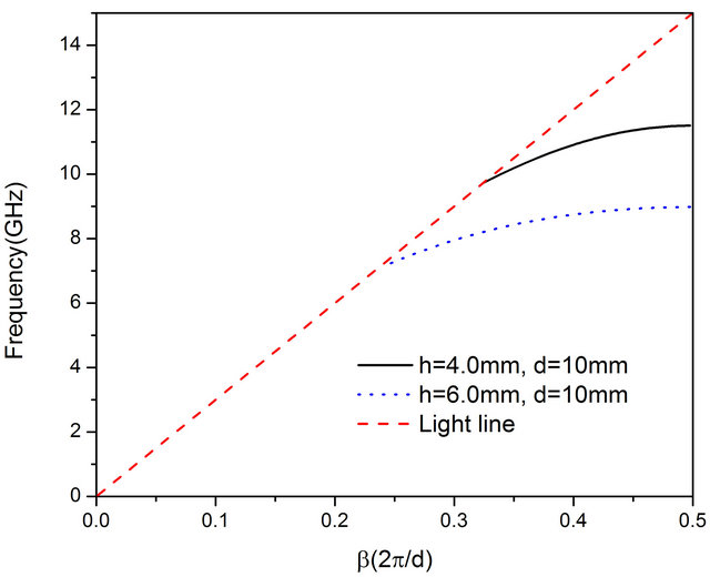 (b)
(b)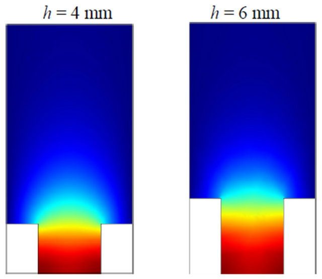 (c)
(c)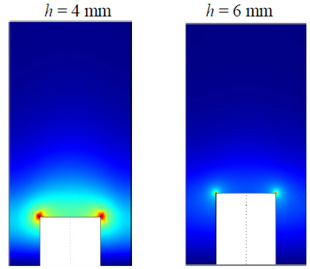 (d)
(d)
Figure 1. (a) Open waveguide based on periodic subwavelength Domino structure supporting spoof SPPs, the width is L, the period is d, the adjacent spacing is a, the height is h and the waveguide lateral width is w; (b) Dispersion line of the plasmonic waveguide for the case d = 10 mm, a = 5 mm, L = 5 mm, the solid black line represents the case h = 4.0 mm, the dotted blue line represents the case h = 6.0 mm; (c) Magnetic field distribution of spoof SPPs at the asymptotic frequency for the two cases; (d) Electric field distribution of spoof SPPs at the asymptotic frequency for the two cases.
 (a)
(a)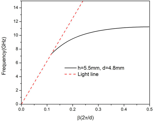 (b)
(b)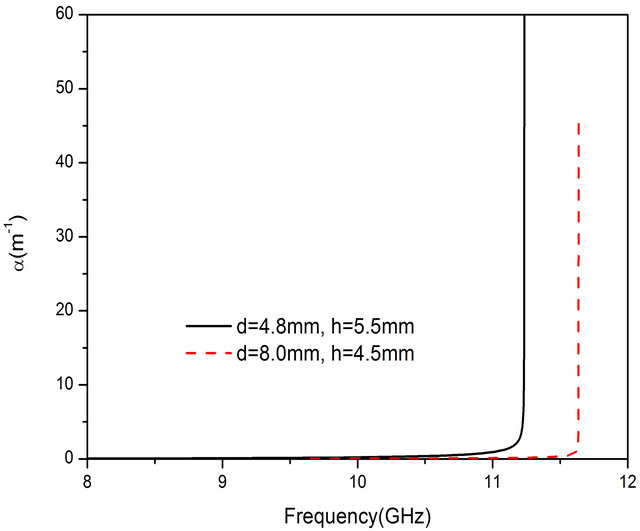 (c)
(c)
Figure 2. (a) Dispersion line of the periodic Domino structure of the case of lattice constant d = 8 mm and height h = 4.5 mm; (b) Dispersion line of the periodic Domino structure of the case of lattice constant d = 4.8 mm and height h = 5.5 mm respectively; (c) Attenuation constants for the cases of Figures 2(a) and (b).
sequently, we can obtain a band pass filter by designing these parameters of the Domino structure. The transmission of the above structure is lossless as the metal is assumed to be PEC, but it is lossy for practical metal due to finite conductance. Utilizing the perturbation method [12- 14], we can calculate the loss of such waveguide made by Aluminum (Al) with finite conductance. The tangential electric field will vanish on the PEC surface, while for the conductor with finite conductivity, there will exist a slight tangential electric field , and a tangential magnetic field
 , they have the relation of
 here
here 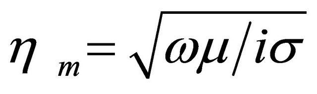 is the characteristic impedance,
  is the unit vector normal to the metallic surface and σ is the conductance of metal. The dissipated power in the metal can be calculated as
 (1)
(1)
The integral area is the whole metallic surface for a Domino lattice unit. We get the tangential magnetic field under the assumption of PEC. By the power conservation principle, the decrease of the total power Pf of the spoof SPPs must be equal to the power dissipated, and the attenuation constant a of the spoof SPPs can be calculated as
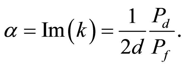 (2)
(2)
Here Pf represents the total time-average power, d is the lattice constant of the plasmonic waveguide and k is the complex propagation constant. Figure 2(c) shows the attenuation constant of this plasmonic open waveguide for the case d = 8.0 mm, h = 4.5 mm and d = 4.8 mm, h = 5.5 mm respectively. The asymptotic frequencies fs are 11.6352 GHz and 11.233 GHz for these two cases. It can be seen that the attenuation constant a is ultra-small at lower frequencies, and it greatly increases as approaching the asymptotic frequency. For example, for the case h = 4.5 mm, when f ≤ 11 GHz, a is smaller than 0.128 m−1, when f ≈ fs, a ≈ 45.19 m−1, and for the case h = 5.5 mm, when f = 11.233 GHz, a ≈ 59.787 m−1. This is because the modal field is highly restricted near the metal surface near the asymptotic frequency to generate much larger loss. As a result, we can adjust the plasmonic open waveguide to work at the frequency a little lower than the asymptotic frequency fs, which has the advantages of both low loss and high field confinement.
3. Experimental Results
To experimentally verify the plasmonic waveguide above, we design and fabricate a metallic structure as shown in Figure 3(a). At each end of the waveguide, there is a transition region of length 50 mm Figure 3(b), where the height of the Domino structure is increased gradually.
As a result, the field distribution from the rectangular waveguide is gradually transformed into the spoof SPP
 (a)
(a)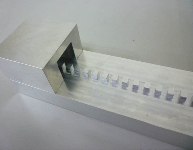 (b)
(b)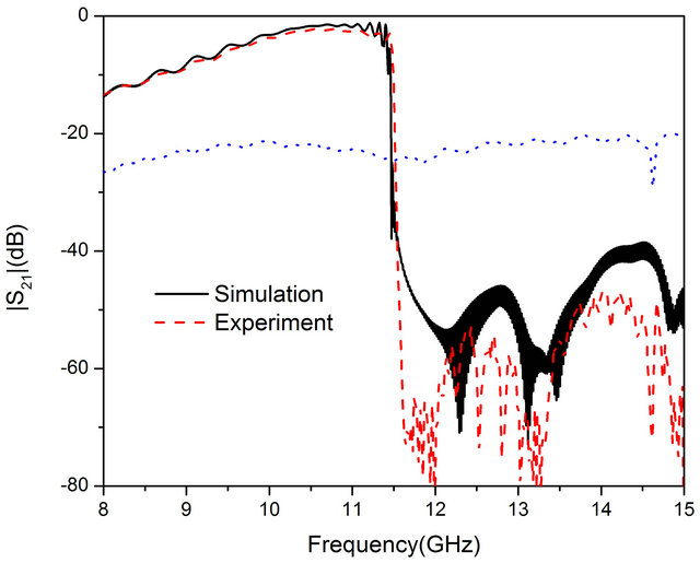 (c)
(c)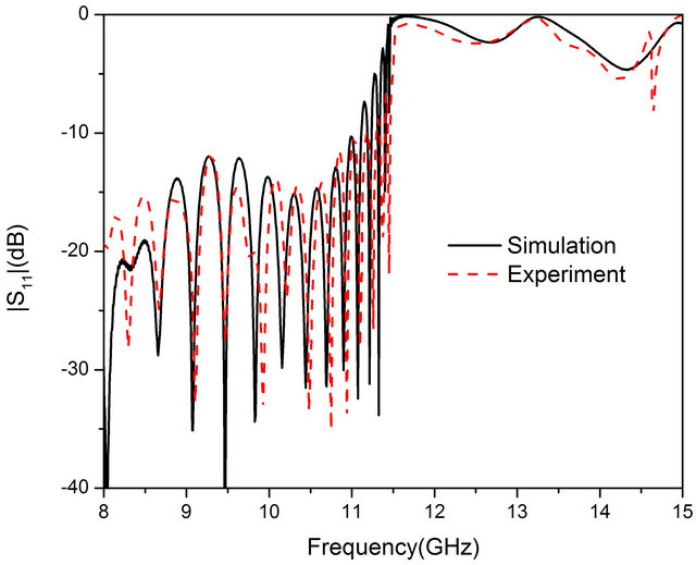 (d)
(d)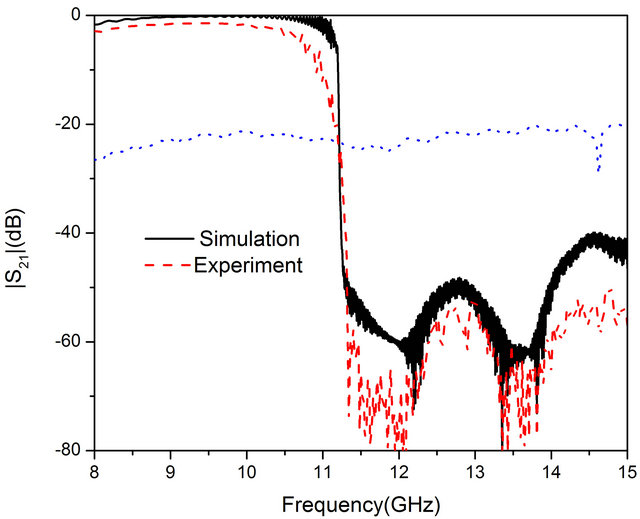 (e)
(e)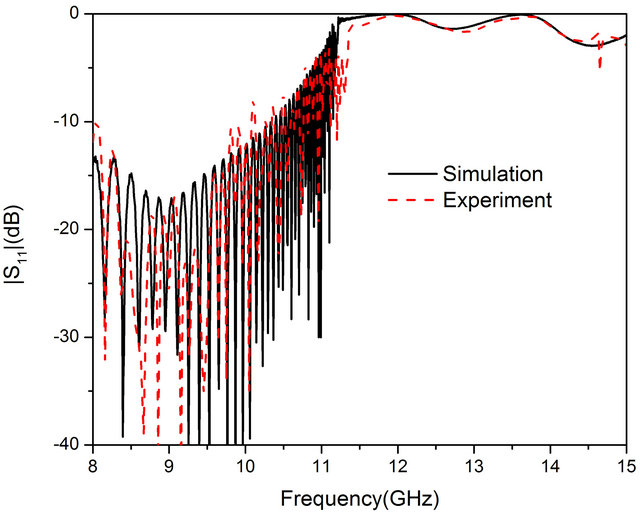 (f)
(f)
Figure 3. (a) The plasmonic open waveguide composed by subwavelength periodic Domino structure; (b) The experimental structure of the plasmonic open waveguide; (c) S21 for the case h = 4.0 mm, d = 10 mm, a = 0.5d m and L = 5 mm; (d) S11 for the case h = 4.0 mm, d = 10 mm, a = 0.5d m and L = 5 mm. The blue line represents the transmission without the subwavelength periodic Domino structure; (e) S21 for the case h = 5.5 mm, d = 4.8 mm; (f) S11 for the case h = 5.5 mm, d = 4.8 mm. The blue line represents the transmission without the subwavelength periodic Domino structure.
field distribution along the transition region, reducing the reflection in the junction between the plasmonic waveguide and the rectangular waveguide adapter. First, consider the case of h = 4 mm, d = 10 mm, a = 0.5 d, L = 5 mm, w = 75 mm, and t = 375 mm with dispersion line shown in solid black line in Figure 1(b). The S parameters of this plasmonic waveguide measured from Vector Network Analyzer (VNA) are displayed in dashed red line Figure 3(c). The experimental value of S21 increases from −13.4 dB at 8 GHz to −2.49 dB at 11.24 GHz, and it falls below −12 dB close to the asymptotic frequency 11.505 GHz, as indicated dash red line. The simulation and experimental results agree well with each other, the slight magnitude difference is due to the loss in experimental metal which is assumed to be PEC in simulation. The measurement of S21 for metallic plane without the Domino structure is also shown in dotted blue line, which proves that the transmission property is induced by the spoof SPP mechanism of the Domino structure. For the case of h = 4.8 mm, d = 5.5 mm with dispersion line shown in solid black line in Figure 2(b). The S parameters of this plasmonic waveguide are displayed in dashed red line Figures 3(e) and (f), the S21 increases from −2.9 dB at 8 GHz to −1.478 dB at 9.645 GHz, then decrease to −9.94 dB at 10.98 GHz, and falls below −24.9 dB above the asymptotic frequency 11.233 GHz. From the previous analysis, the plasmonic waveguide with these geometric parameters has high modal field confinement, as a result, the EM field from the input can be effectively guided to the output by such Domino structure. The slight difference between the experimental and simulation is caused by the limit of fabrication precision.
4. Conclusion
In conclusion, we have studied in numerical and experiment the plasmonic open waveguide constructed by periodic subwavelength Domino structure, which supports spoof SPPs with high modal field confinement. Such waveguide has metallic open structure, whose geometric parameters can be adjusted to control the working frequency bandwidth. We utilized waveguide adaptor in our experiment, so that the S parameters of the Domino structure can be obtained to analyze the transmission properties. This kind of the waveguide structure can be applied in high power microwave transmission system.
5. Acknowledgements
The financial supports by the National Science Council of ROC under Grant Nos. NSC 100-2112-M-216-002, NSC 100-2221-E-216-015 and the National Natural Science Foundation of China under Grant No. 60971062 are gratefully acknowledged.
REFERENCES
- H. Raether, “Surface Plasmons,” Springer-Verlag, Berlin, 1988.
- J. B. Pendry, L. Martin-Moreno and F. J. Garcia-Vidal, “Mimicking Surface Plasmons with Structured Surfaces,” Science, Vol. 305, No. 5685, 2004, pp. 847-848. doi:10.1126/science.1098999
- F. J. Garcia-Vidal, L. Martin-Moreno and J. B. Pendry, “Surfaces with Holes in Them: New Plasmonic Metamaterials,” Journal of Optics A: Pure and Applied Optics, Vol. 7, No. 2, 2005, pp. S97-S101. doi:10.1088/1464-4258/7/2/013
- T. Jiang, L. F. Shen, X. Zhang and L. Ran, “High-Order Modes of Spoof Surface Plasmon Polaritons on Periodically Corrugated Metal Surface,” Progress in Electromagnetics Research M, Vol. 8, 2009, pp. 91-102. doi:10.2528/PIERM09062901
- F. J. Garcia de Abajo and J. J. Saenz, “Electromagnetic Surface Modes in Structured Perfect-Conductor Surfaces,” Physical Review Letters, Vol. 95, 2005, Article ID: 233901.
- J. J. Wu, T. J. Yang and L. F. Shen, “Subwavelength Microwave Guiding by a Periodically Corrugated Metal Wire,” Journal of Electromagnetic Waves and Applications, Vol. 23, No. 1, 2009, pp. 11-19. doi:10.1163/156939309787604616
- P. Hibbins, B. R. Evans and J. R. Sambles, “Experimental Verification of Designer Surface Plasmons,” Science, Vol. 308, No. 5722, 2005, pp. 670-672. doi:10.1126/science.1109043
- J. J. Wu, “Subwavelength Microwave Guiding by Periodically Corrugated Strip Line,” Progress in Electromagnetics Research, Vol. 104, 2010, pp. 113-123. doi:10.2528/PIER10021202
- J. J. Wu, H. E. Lin, T. J. Yang, H. J. Chang and and I. J. Hsieh, “Low-Frequency Furface Plasmon Polaritons Guided on a Corrugated Metal Striplines with Subwavelength Periodical Inward Slits,” Plasmonics, Vol. 6, No. 1, 2011, pp. 59-85. doi:10.1007/s11468-010-9169-0
- F. J. García de Abajo, “Light Scattering by Particle and Hole Arrays,” Review of Modern Physics, Vol. 79, No. 4, 2007, pp. 1267-1290. doi:10.1103/RevModPhys.79.1267
- L. S. Shen, X. D. Chen and T. J. Yang, “Terahertz Surface Plasmon Polaritons on Periodically Corrugated Metal Surfaces,” Optics Express, Vol. 16, No. 5, 2008, pp. 3327-3333. doi:10.1364/OE.16.003326
- X. F. Zhang, L. F. Shen, J.-J. Wu and T.-J. Yang, “Terahertz Surface Plasmon Polaritons on a Periodically Structed Metal Film with High Confinement and Low Loss,” Journal of Electromagnetic Waves and Applications, Vol. 23, No. 17-18, 2009, pp. 2451-2460.
- J. A. Kong, “Electromagnetic Wave Theory,” EMW Publishing, Cambridge, 2005.
- R. E. Collin, “Field Theory of Guided Waves,” McGrawHill Book Co., New York, 1960.
NOTES
*Corresponding author.