Journal of Electromagnetic Analysis and Applications
Vol.4 No.8(2012), Article ID:21533,7 pages DOI:10.4236/jemaa.2012.48045
Enhancement of Characteristics of Antenna Arrays Employing S-Shaped Resonators
![]()
Innov’COM, Higher School of Communications of Tunis, University of Carthage, Tunis, Tunisia.
Email: *b_aouadi@yahoo.fr
Received June 20th, 2012; revised July 18th, 2012; accepted July 28th, 2012
Keywords: G-Shaped Monopole Antenna; MIMO Systems; S-Shaped Resonators; Mutual Coupling; Antenna Correlation
ABSTRACT
This paper illustrates a simple kind of tri-band printed G-shaped monopole antenna for Multiple-Input-Multiple-Output (MIMO) systems. The proposed antenna is used to achieve three operating frequencies, 2.45 GHz, 5.2 GHz and 8.2 GHz for wireless communications. To improve the isolation between the two radiating elements, we use left-handed materials composed of only S-shaped resonators to get negative refractive index at the three operating frequencies. When one layer of S-shaped resonators is employed, the antenna correlation, the diversity gain and the bandwidth are also enhanced. The simulated results are presented and evaluated with and without left-handed materials.
1. Introduction
Over the past few years, there has been an increasing worldwide research interest in Multiple-Input-MultipleOutput (MIMO) systems, as they have been shown to have the potential for improved capacity, spectral efficiency and reliability as compared to Single-Input-SingleOutput (SISO) communications using single antennas [1,2]. MIMO technology is a breakthrough in the field of modern wireless communications, and is poised to play a significant role in the implementation of next generation’s wireless products and networks. However, correlation of the signals at the different antenna elements can considerably decrease the capacity of a MIMO system [3]. In addition, with a small separation, printed antenna arrays suffer from relatively high level of mutual coupling between individual elements due to surface waves [4]. Otherwise, the mutual coupling refers to the electromagnetic interactions between the elements of an antenna array. Some of the energy transmitted by a transmit antenna element is transferred to the other elements. Correspondingly, a portion of the energy in the incident field of a receive antenna element is transferred to the nearby elements. As a result, the feed current on each transmit antenna in an antenna array does not solely consist of the current when they are transmitting in isolation, but also of the current induced by the other antenna elements in proximity. The same argument follows for the induced current on the received elements of the array [5]. Many studies have been performed to improve the isolation characteristic of a MIMO antenna using a shorting strip [6], a new ground structure with slits to act as a bandstop filter [7], a corrugated ground plane [8], a 180˚ hybrid couplers [9], an Electromagnetic Band Gap (EBG) structures [10] and metamaterials [11,12]. In fact, metamaterials have the property to significantly reduce the mutual coupling between each antenna in MIMO systems. Negative permittivity materials can be realized using thin wires [13], and negative permeability can be achieved using Split-Ring Resonators (SRRs) [14]. In [11,12], metamaterials structures have been used to achieve a negative permeability at the operating frequency. Furthermore, in [11], they have been employed to reduce the mutual coupling between two high profile monopoles whereas in [12], they have been used to improve the isolation between two closely separated low profile printed monopoles. In this work, we use S-shaped resonators to get a negative refractive index at 2.45 GHz, 5.2 GHz and 8.2 GHz. One layer of S-shaped resonators is inserted between the two structures to fructify the performances of the proposed MIMO systems. On the other hand, design of multi-band antennas with low-profile, lightweight and low cost for wireless communications like the WiFi and the WiMAX has gained increasing demands. A novel and simple printed dual-band with two different sizes T-shaped antenna which generates two separate resonant is proposed in [15]. Likewise, another kind of dual-band printed G-shaped monopole antenna is presented in [16]. In [16], the antenna consists of a G-shaped monopole and a microstrip feedline, which provide two resonant paths of different lengths to achieve the 2.4 GHz and 5.2 GHz dual-band operation far WLAN applications. Moreover, it is noted that the microstrip line needs a ground plane printed on the back side of substrate. In this study, we have used a G-shaped monopole antenna for our proposed MIMO systems but we have added a gap between this ground plane and the microstrip line to achieve the three operating frequencies.
This paper is organized as follows: Section 2 discusses the antenna structure with different values of the gap. The dimensions of the proposed S-shaped resonators and the determination of the refractive index are illustrated in Section 3. The results of simulations for different characteristics of antenna arrays with and without S-shaped resonators are studied in Section 4. Section 5 presents the conclusion.
2. Antenna Geometry
Figure 1 shows the design of the antenna which is fed by a 50 Ω microstrip line and built on a FR-4 substrate with 48 × 61.2 mm2 surface area, 0.8 mm thickness with relative permittivity of 4.4 and loss tangent of 0.002. The antenna element doesn’t need conductor-backed ground plane [16]. The strip width of both the G-shaped antenna and the microstrip feedline is set at 1.53 mm. There are two grounds with dimensions of (23.235 –g) × 30 mm2 lying symmetrically on each side of the microstrip line and printed on the back side of substrate.
As mentioned in [16] and without employing the gap, if we want to fix the antenna resonance in the 2.4 GHz band, we need to adjust the length L1 = l1 + l2 + l3 + l4.
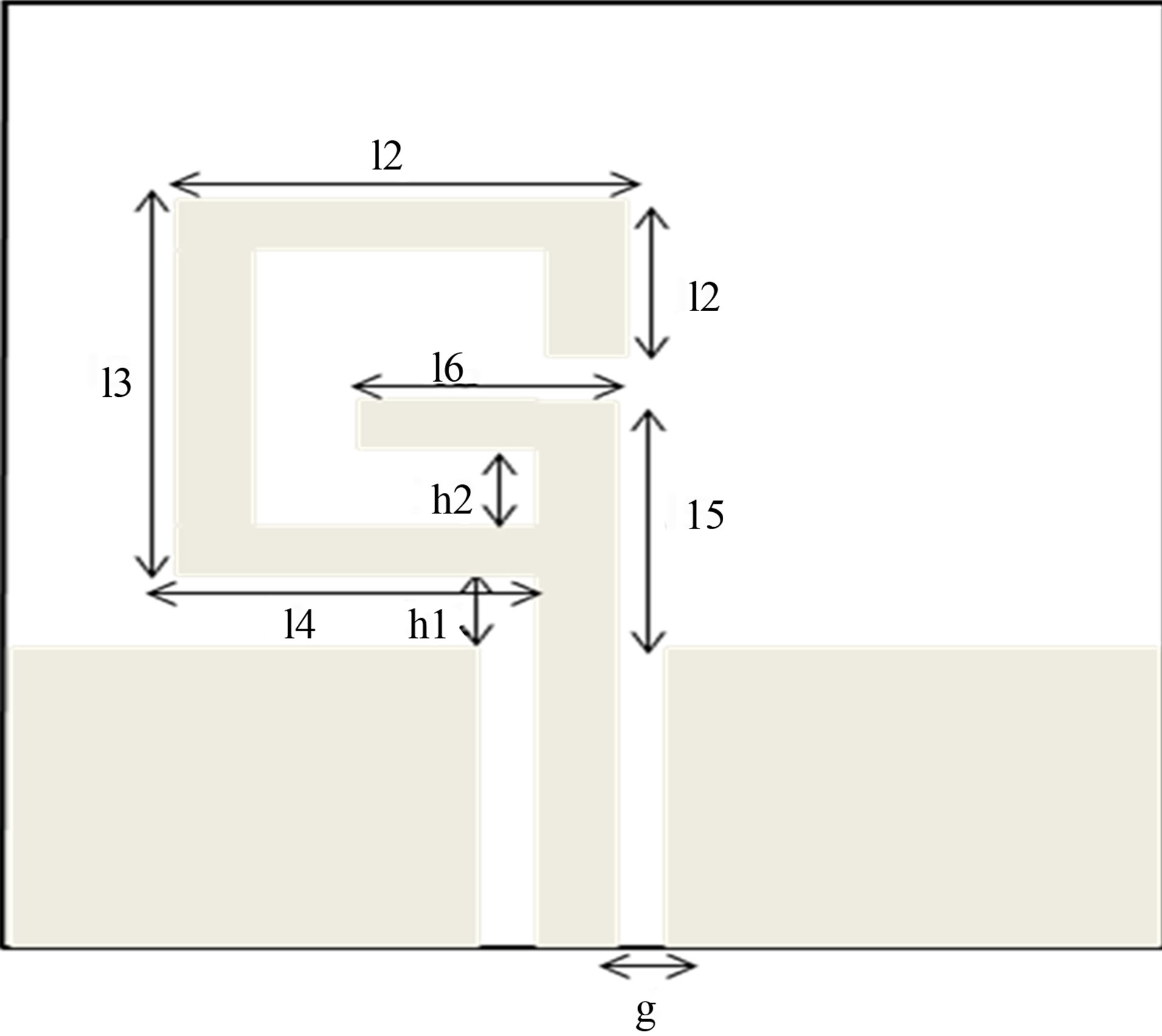
Figure 1. Geometry of the proposed antenna.
However, tuning the length L2 = l5 + l6, can fix another antenna resonance in the 5.2 GHz band. Likewise, to increase the impedance matching bandwidth, it’s necessary to arrange the dimensions (l1, l2, l3, l4, h1) and (l5, l6, h1, h2) to improve the 2.4 GHz and 5.2 GHz band, respectively. Ansoft High-frequency structure simulator V13.0 (HFSS) [17] was used, after adding the gap, to optimize the necessary parameters to achieve the three resonance frequencies at 2.45 GHz, 5.2 GHz and 8.2 GHz to satisfy requirements of wireless applications. A series of typical dimensions are presented in Table 1.
On the other hand, we want, now, to study the impact of employing the gap between the mictrostip line and each ground plane which was printed on the back side of substrate. This study is elucidated in Figure 2.
It’s obvious that the use of the gap affect the resonance frequency. Thus, to obtain the three operating frequencies 2.45 GHz, 5.2 GHz and 8.2 GHz, we must use a gap with dimension of 0.5 mm. In this case, the G-shaped antenna resonate at 2.45 GHz, 5.2 GHz and 8.2 GHz with a return loss of –19.08 dB, –17.45 dB and –17.12 respectively.
3. S-Shaped Resonators Configuration and Retrieval of the Index of Refraction
Metamaterials are a class of composite materials artificially constructed to exhibit exceptional properties not readily found in nature. In particular, there has been high level interest in studying materials which can be characterized by simultaneously negative permittivity and permeability over a certain frequency band. This type of
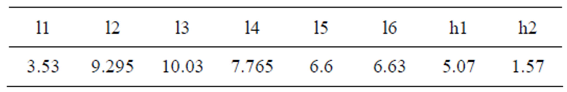
Table 1. G-Shaped antenna dimensions (mm).
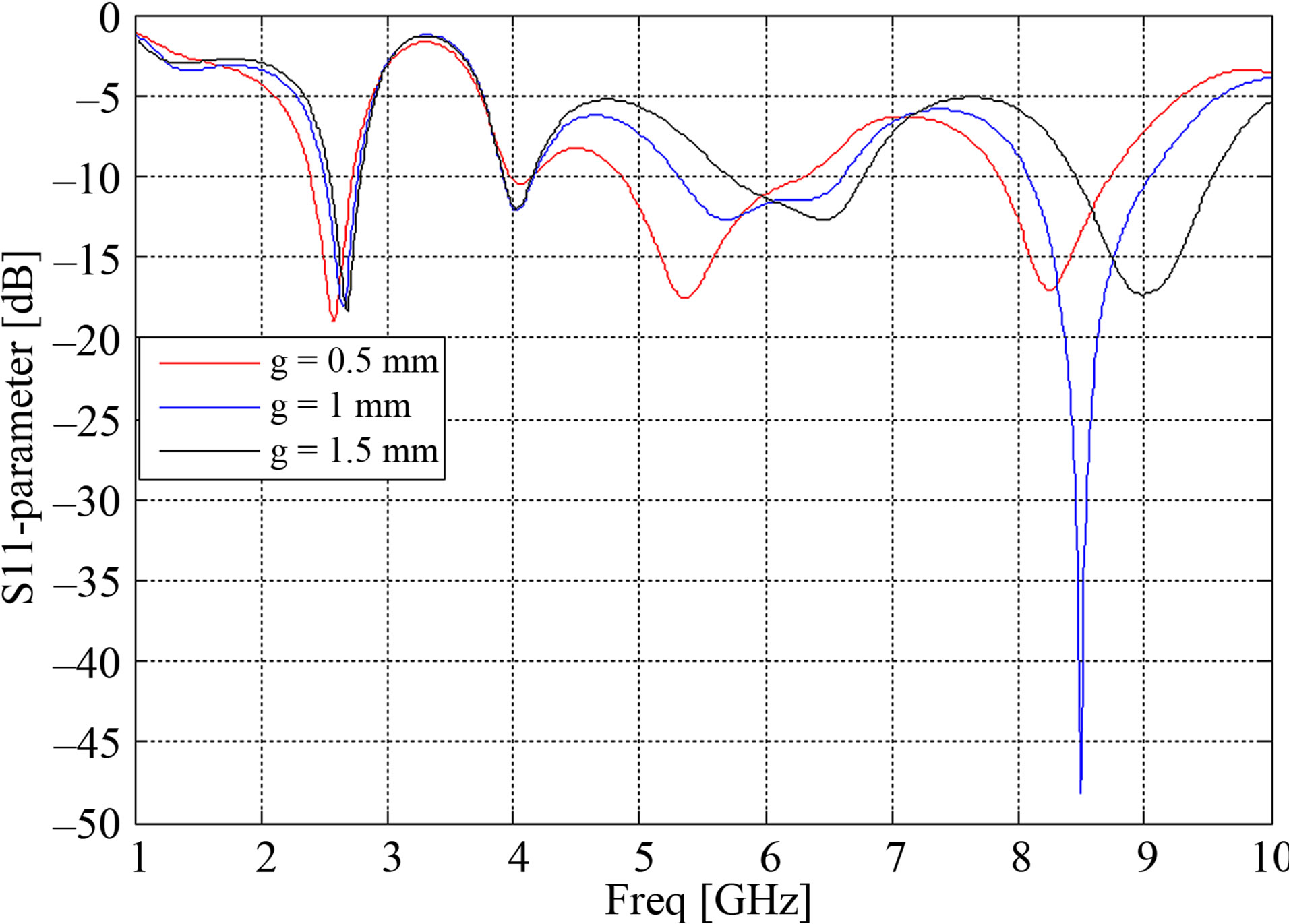
Figure 2. The effect on operating frequency due to the use of the gap.
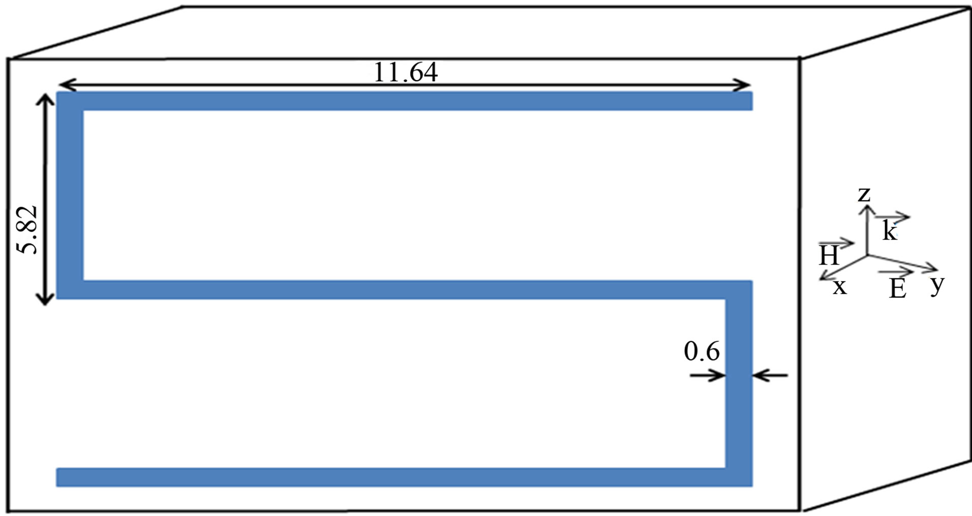
medium was originally studied by Victor Veselago in 1968, who termed such media Left Handed (LH) due to the LH triad formed by the electric field vector, the magnetic field vector, and the phase propagation vector [18]. The realization of most of the Left-Handed Materials (LHM) in many experimental works relies on SRR and rod geometries [19,20]. However, Prosvirnin [21] proposed a new kind of LH composed of only S-shaped resonators to get a negative refractive index. In this paper, we suggest two forms of S-shaped resonators, as shown in Figure 3, to provide negative effective indexes around the three resonance frequencies. Indeed, the resonance frequency is determined by the capacitance and inductance of each structure [22]. The S-shaped resonator is printed on a Rogers RO3003 substrate with 12.24 × 12.24 mm2 surface area, 0.8 mm thickness with relative permittivity of 3 and loss tangent of 0.0013. Then, the S-shaped resonator is excited by an electromagnetic wave with propagation vector (k) along the z-axis, electric field vector (E) along the y-axis and magnetic field vector (H) along the x-axis, as shown in Figure 3.
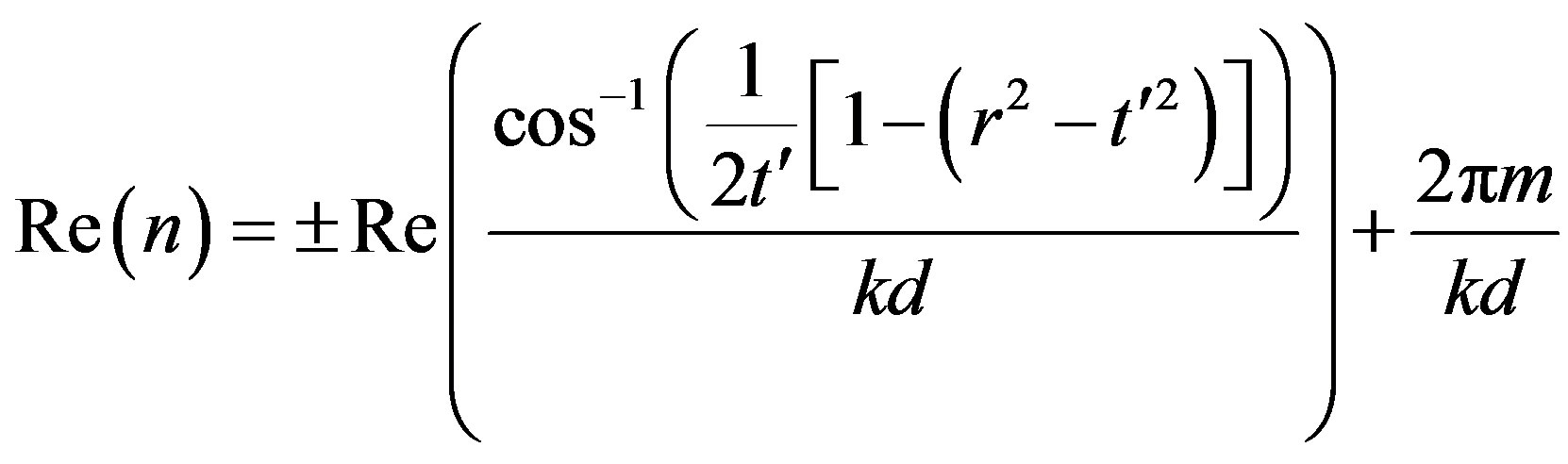
Moreover, the effective index can be determined from the simulated S-parameters [23,24] of a wave normally incident on a slab of the metamaterial. Likewise, we can retrieve the real part and the imaginary part of the refractive index using the Equations (1) and (2).
 (a)
(a)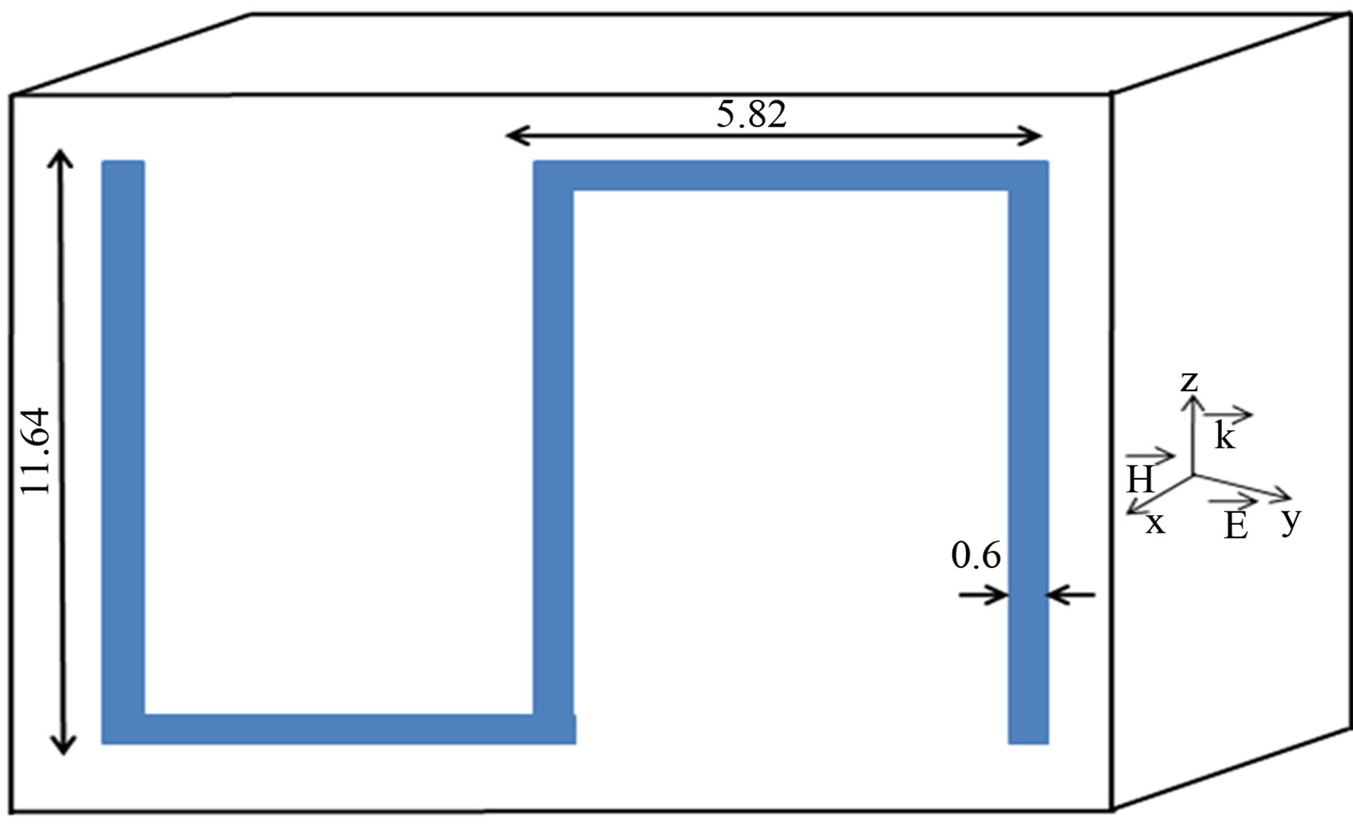 (b)
(b)
Figure 3. Design of the two forms of the proposed S-shaped resonator. (a) First form; (b) Second form.
 (1)
(1)
 (2)
(2)
where  is the normalized transmission coefficient (
 = exp(ikd)t), r is the reflection coefficient, k = ω/c is the wavenumber of the incident wave, d is the length of material and m is an integer. For the first form, the real part of the refractive index is –1.961, –0.014 and –1.571 whereas it becomes –0.014, –0.023 and –1.187 for the three operating frequencies 2.45 GHz, 5.2 GHz and 8.2 GHz respectively.
4. Results of Simulations and Discussions
4.1. Improvement of Mutual Coupling
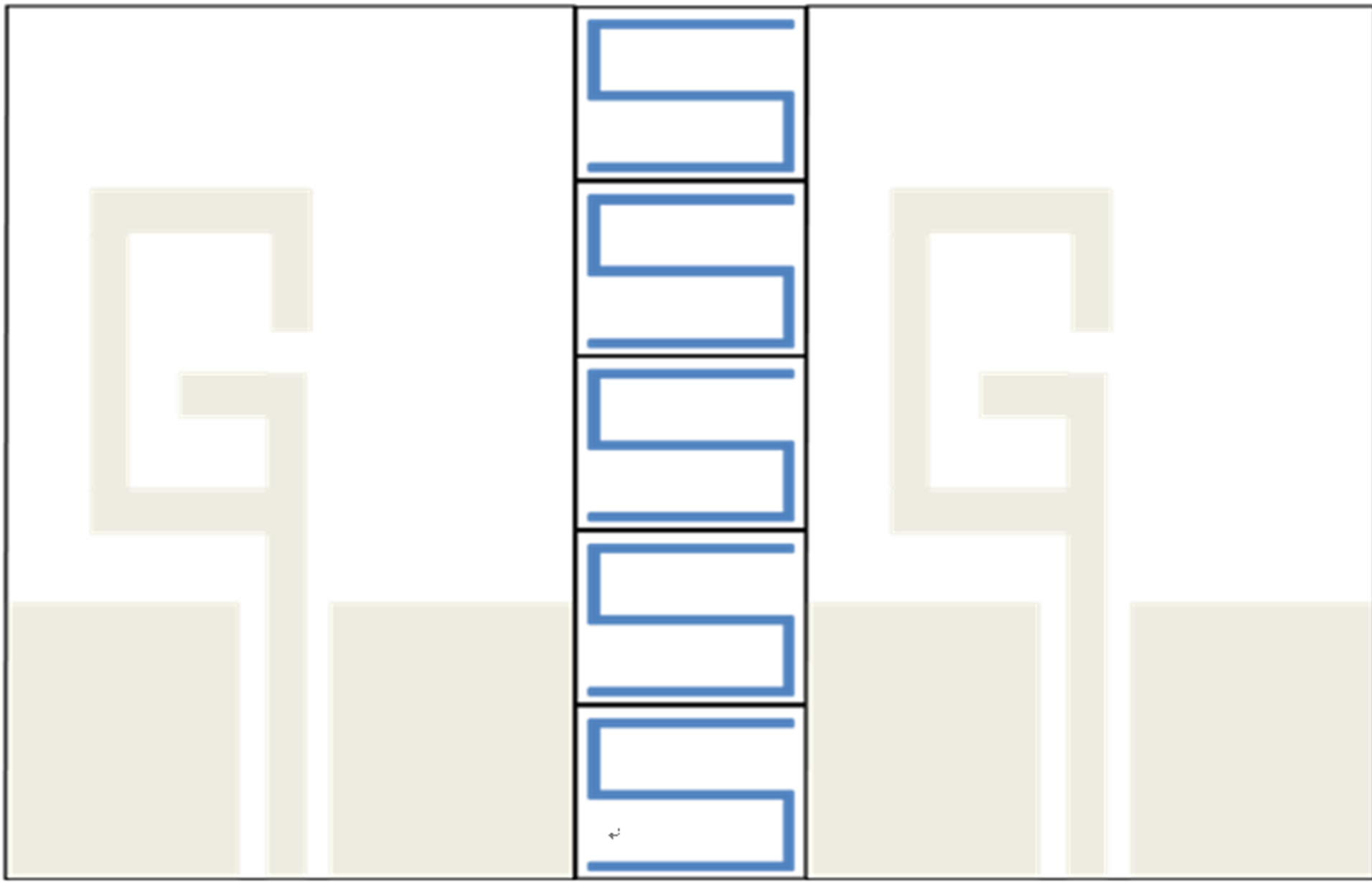
In this section, we first study the different configurations of array antenna using S-shaped resonators as shown in Figure 4. Then, the second part is devoted to describe the isolation between each G-shaped monopole antenna as shown in Figure 5. One layer of S-shaped resonators was used in between a two-element planar antenna array to study its effect on antenna mutual coupling and surface wave. The distance between the antenna and the layer of S-shaped resonators is 12.24 mm (λ/10, λ/5 and λ/3 at 2.45 GHz, 5.2 GHz and 8.2 GHz respectively, where λ is the free space wavelength). Otherwise, for the case number 1, the layer of S-shaped resonators consists of 5 units of the first form of LHM whereas, for the second case, it was composed by 5 units of the second form of LHM. Besides, for the final case, we have used both forms but one by one.
The electrical isolation between the antennas should be less than –20 dB to maintain the performance of the MIMO system. Indeed, the mutual coupling, without LHM, measured in terms of S12, is –25 dB, –29 dB and –34 dB at 2.45 GHz, 5.2 GHz and 8.2 respectively. To further ameliorate this characteristic, we have suggested using one of the cases mentioned above. Likewise, as shown in Figure 5, it’s obvious that when we use one layer S-shaped resonators for each case, we have achieved excellent isolation properties (much less than –20 dB). For the first case, the simulated isolation is –35 dB, –26.66 dB, and –28.14 dB respectively compared to –20.42 dB, –38.65 dB and –42.14 dB at 2.45 GHz, 5.2 GHz and 8.2 respectively. For the third case which can be regarded as the optimal one, the isolation becomes –35 dB, –34 dB and –37 dB at 2.45 GHz, 5.2 GHz and 8.2 respectively. For other performance criteria, we will be interested only in the third case.
4.2. Enhancement of Bandwidth
Figure 6 shows the measured return loss characteristics of the designed MIMO systems with and without S-shaped resonators. The 10 dB bandwidth without metamaterials is approximately 350 MHz, 1.52 GHz and 620 MHz whereas it was 380 MHz, 1.53 GHz and 900 MHz, when we use S-shaped resonators, at 2.45 GHz, 5.2 GHz and 8.2 respectively. Thus, we note a significant increase in bandwidth thanks to LHM.
 (a)
(a)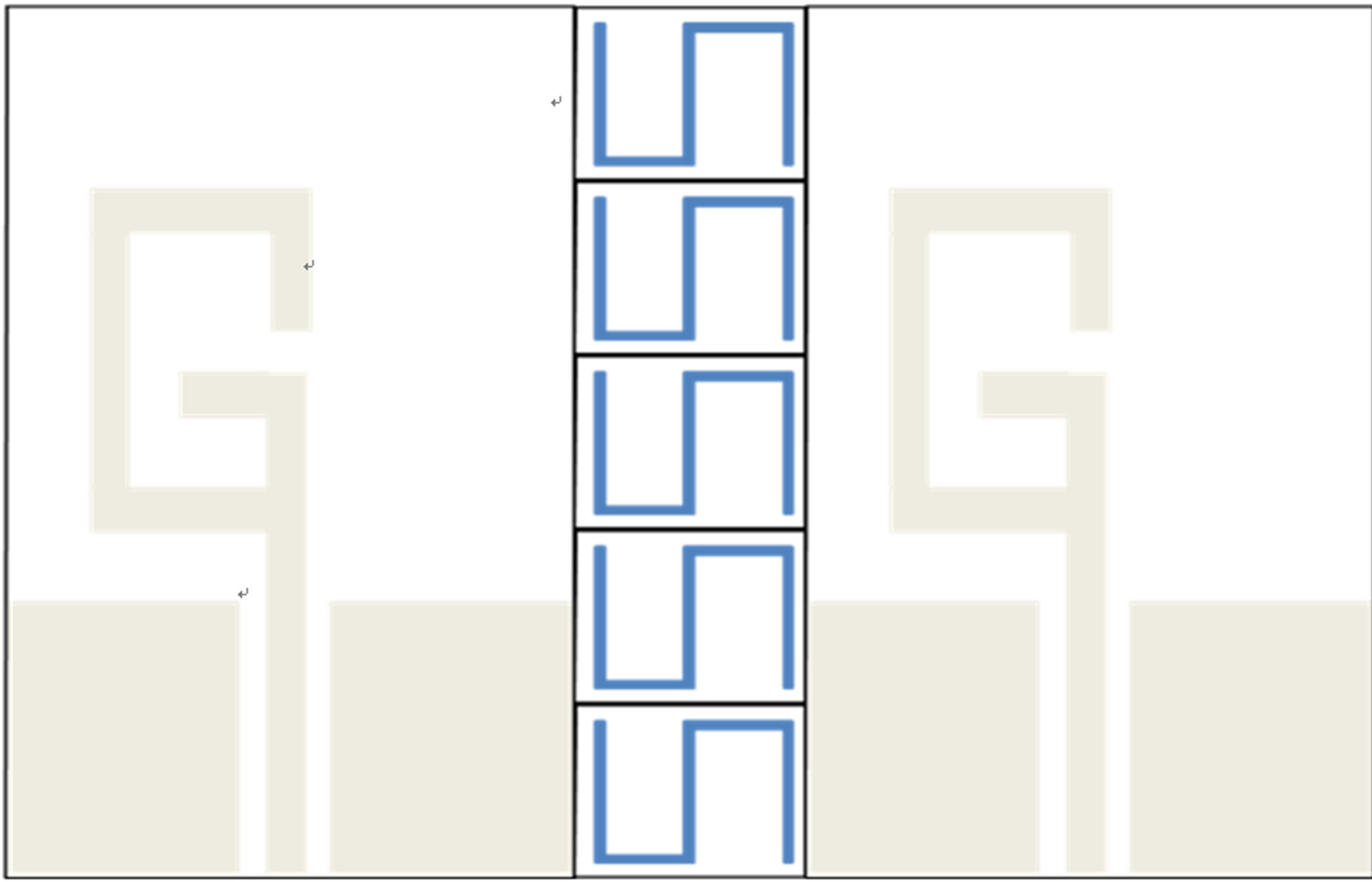 (b)
(b)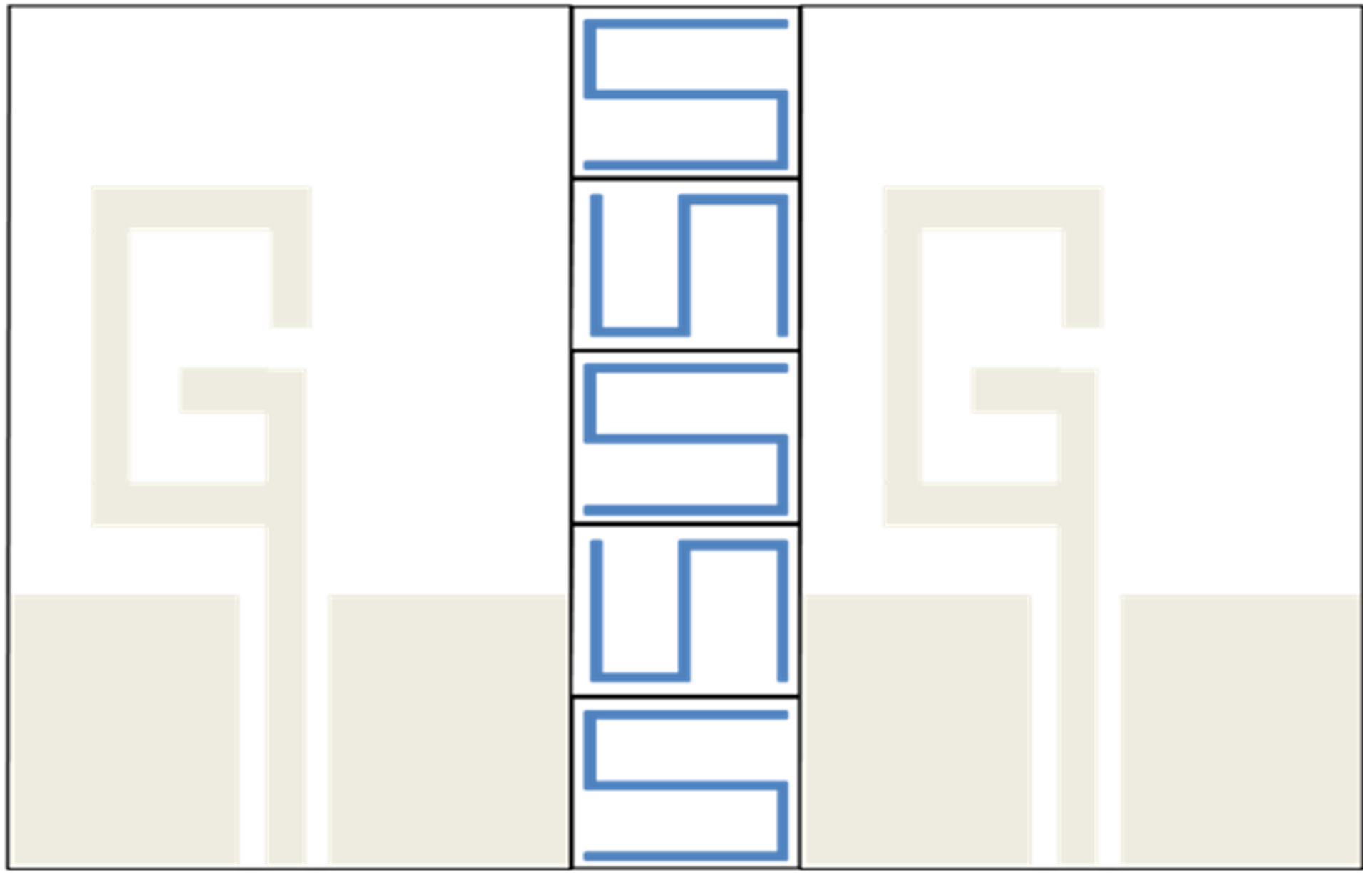 (c)
(c)
Figure 4. Different configurations of array antenna using S-shaped resonators. (a) Case 1; (b) Case 2; (c) Case 3.
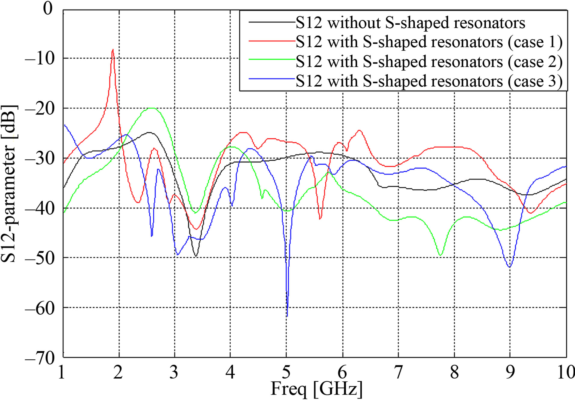
Figure 5. Mutual coupling with and without S-shaped resonators.
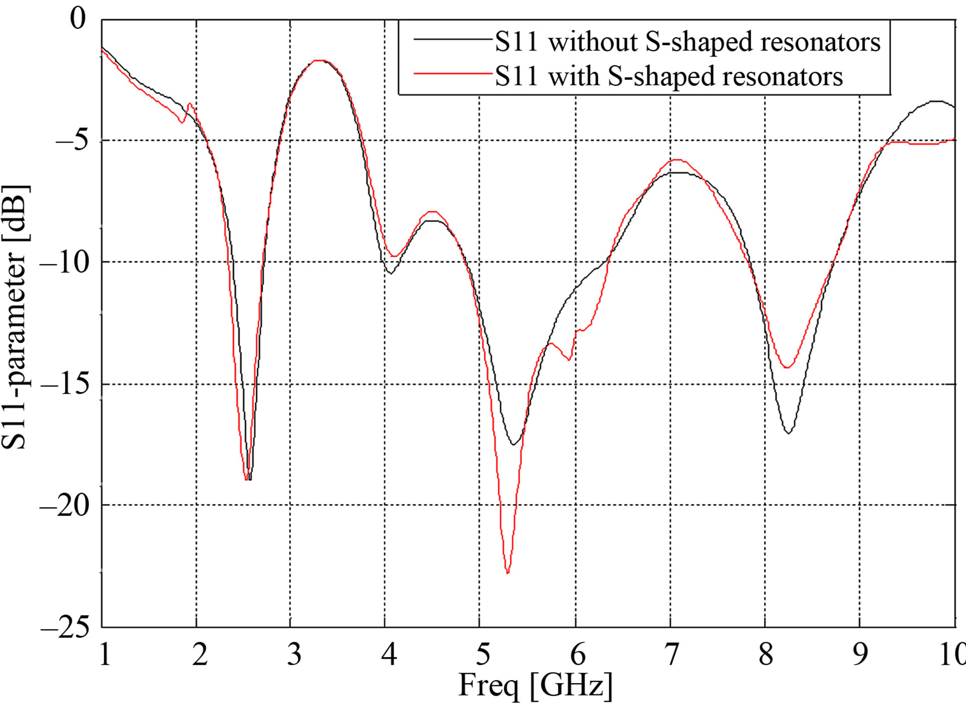
Figure 6. Simulated return loss with and without S-shaped resonators.
4.3. Correlation and Diversity Gain
In the design process of a MIMO antenna, the envelope correlation and diversity gain must receive special consideration. In fact, there exists an approximate relationship between diversity gain (Gapp) and correlation (ρ) that can be written mathematically [23] as in Equation (3).
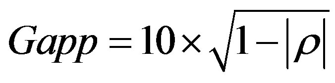 (3)
(3)
Likewise, in the MIMO system, the minimum value of correlation is significant in determining antenna diversity performance [24]. The envelope correlation can be calculated from the scattering parameters of the antennas using the elegant expression in [25] under the assumption of lossless antennas and a uniform field distribution.
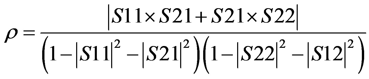 (4)
(4)
As shown in Figures 7 and 8, the values of correlation and diversity gain are clearly fructified when we use the layer of S-shaped resonators. On the one hand, for the first parameter, it’s equal to 0.073, 0.184 and 0.177 compared respectively to 0.061, 0.082, and 0.098, after employing metamaterials, at 2.45 GHz, 5.2 GHz and 8.2 respectively. On the other hand, for the second characteristic of MIMO systems, it’s equal to 1.753 dB, 1.072 dB and 2.677 dB
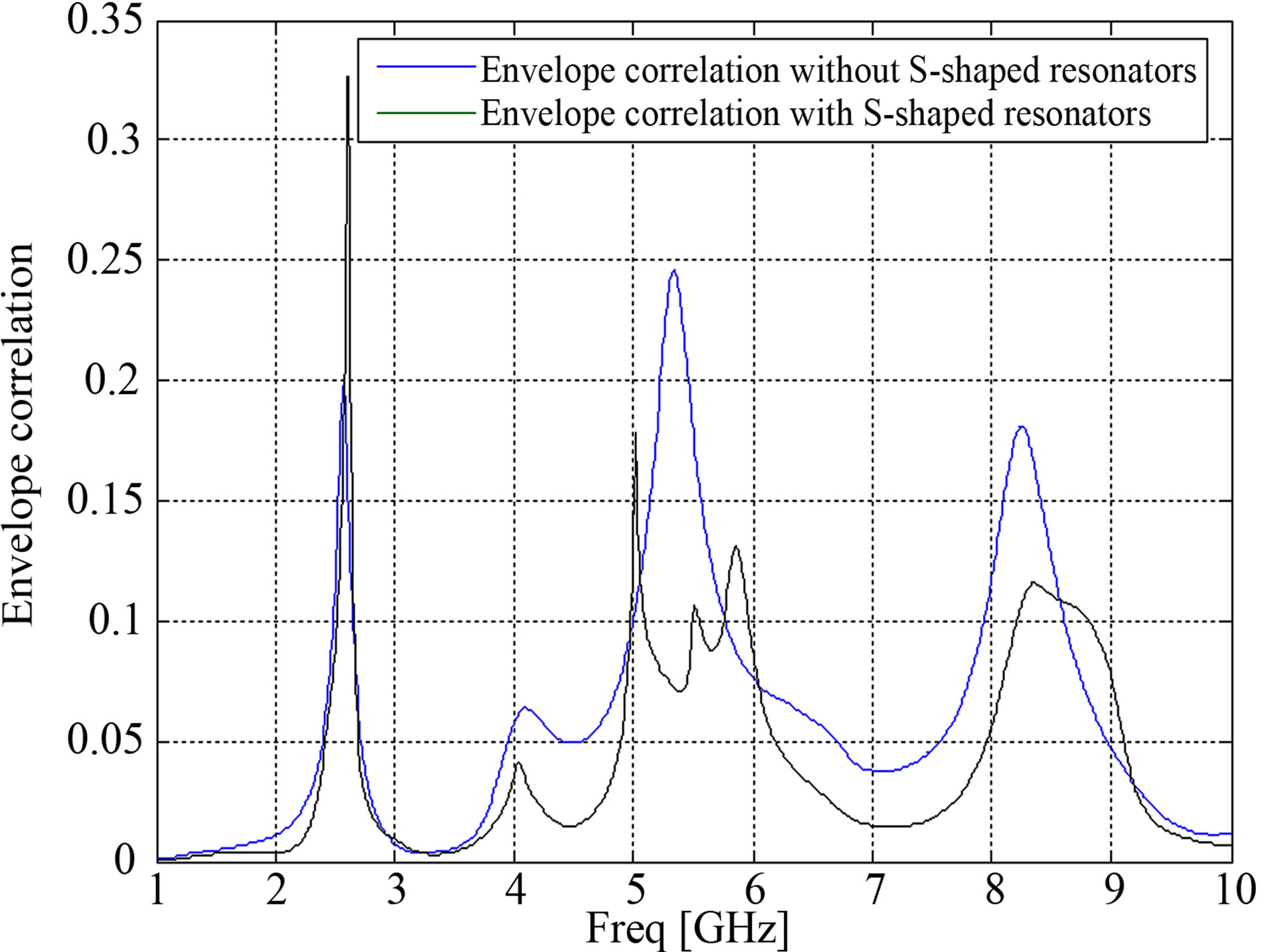
Figure 7. Simulated correlation with and without S-shaped resonators.
whereas it becomes 3.127 dB and 2.956 dB and 2.82 dB at 2.45 GHz, 5.2 GHz and 8.2 respectively thanks to using S-shaped resonators. Therefore, we can confirm that we have achieved the minimum value of correlation and also we have increased the diversity gain that reflect higher antenna diversity at the three operating frequencies.
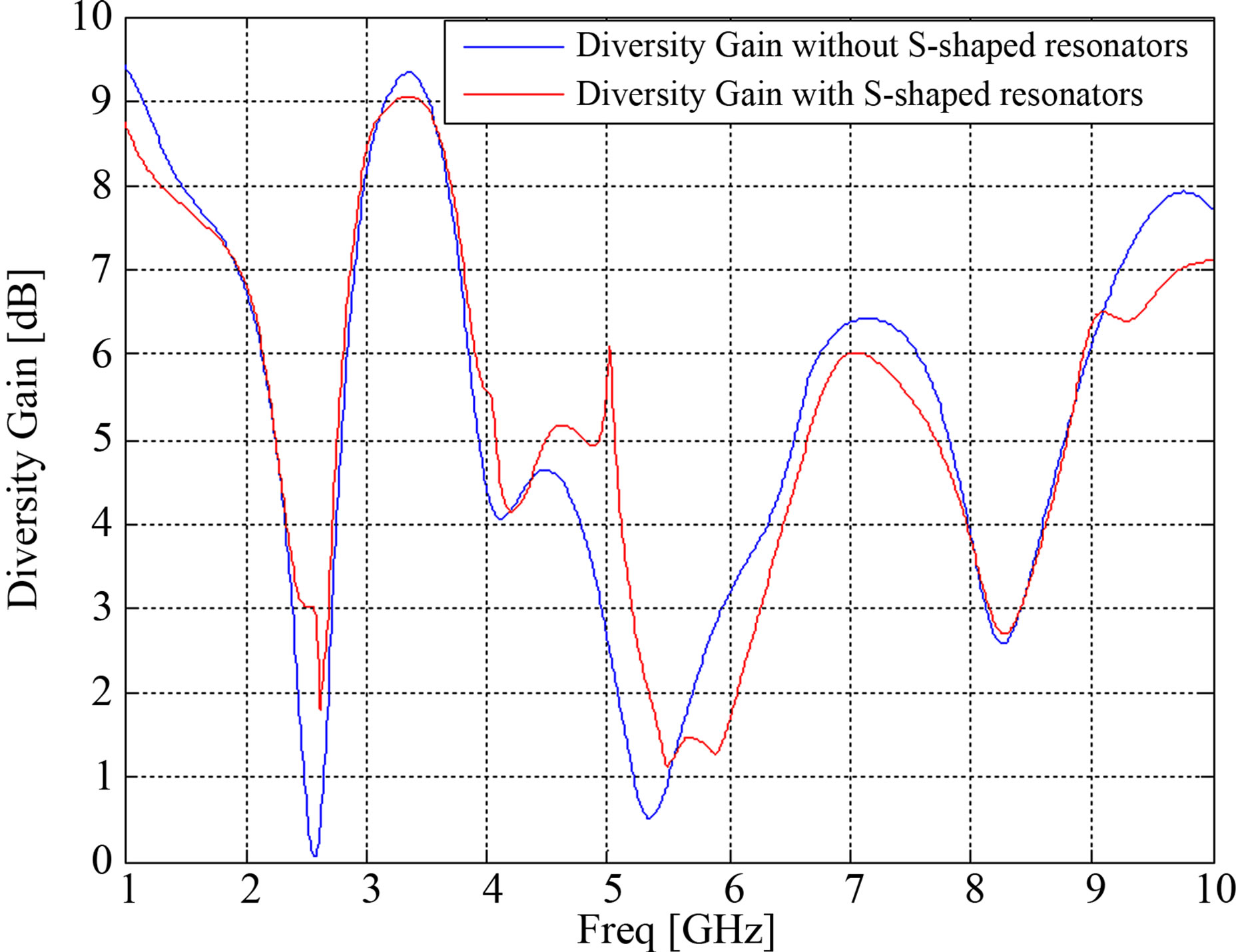
Figure 8. Simulated diversity gain with and without S-shaped resonators.
 (a)
(a)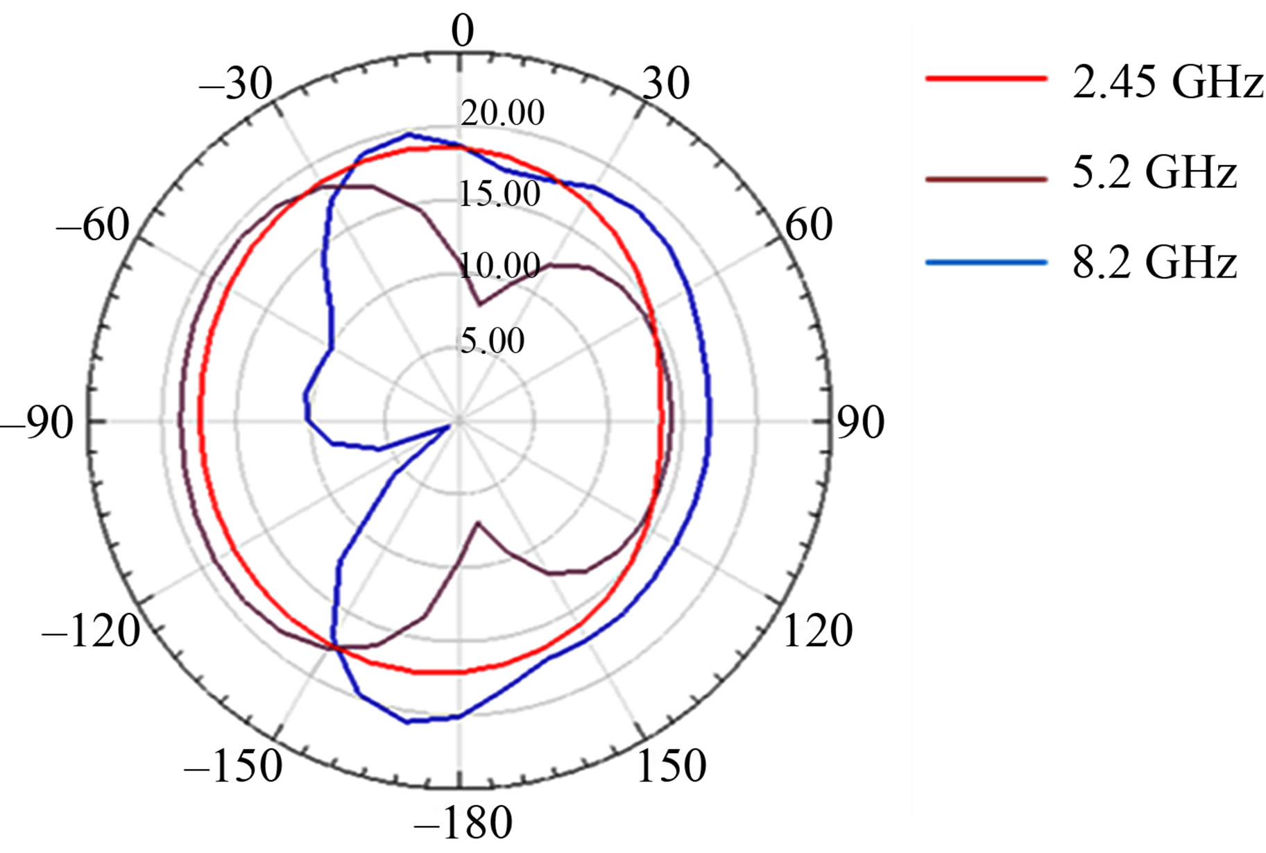 (b)
(b)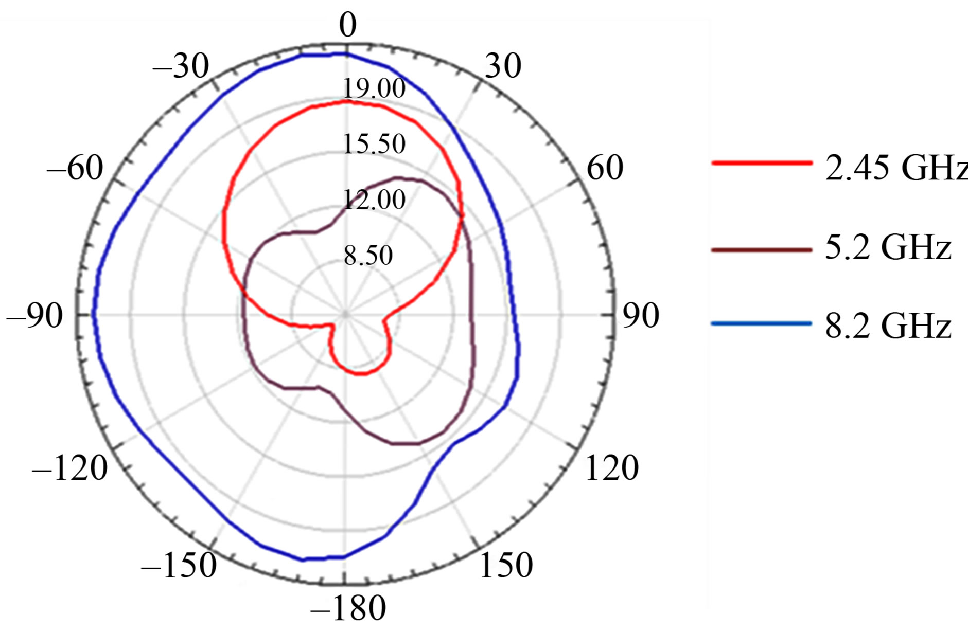 (c)
(c)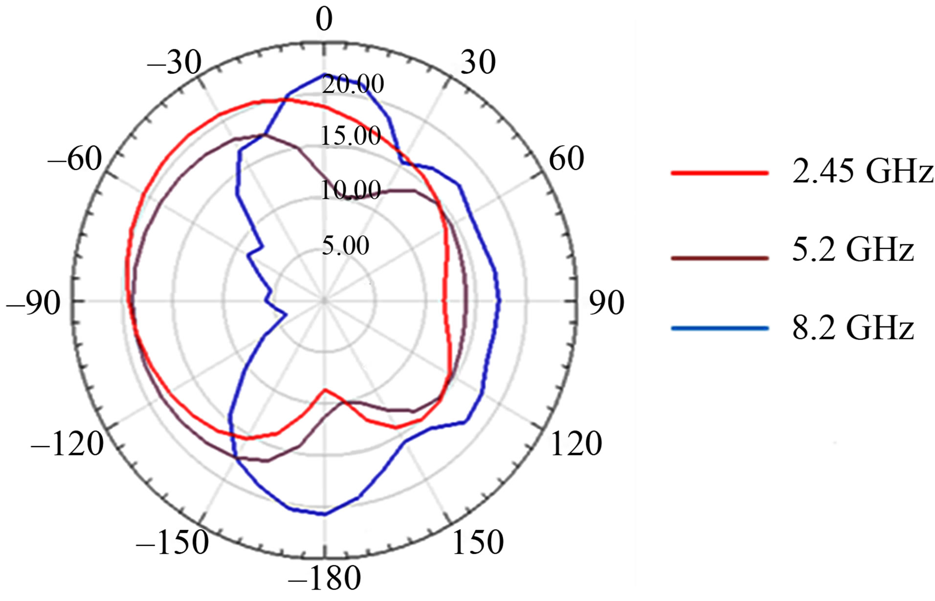 (d)
(d)
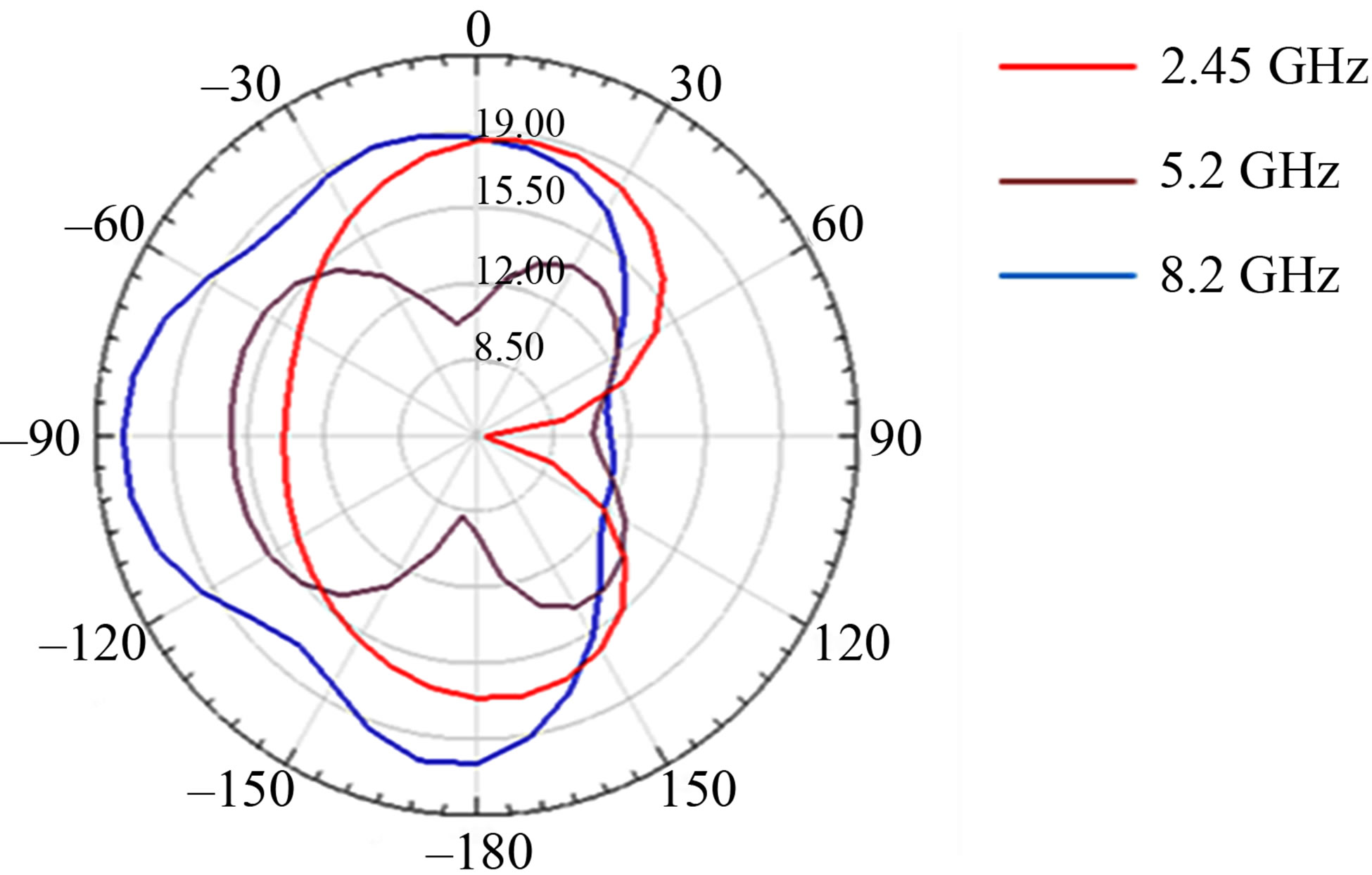
Figure 9. Farfield radiation patterns. (a) E-plane without LHM; (b) H-plane without LHM; (c) E-plane with LHM; (d) H-plane with LHM.
4.4. Simulated Radiation Patterns
Figure 9 indicates the simulated radiation patterns of the MIMO systems with and without S-shaped resonators. Certainly, it is being considered good to have an omnidirectional pattern of the antennas provided they are being employed in the wireless communications. The radiation patterns is nearly omni-directional in H-plane and E-plane when we use Left-Handed Materials instead of the other case without S-shaped resonators.
5. Conclusion
This work has presented a study of G-shaped antenna arrays for MIMO radio communications with and without using one layer of S-shaped resonators between the two radiating elements at three operating frequencies, 2.45 GHz, 5.2 GHz and 8.2 GHz. We have evaluated the MIMO antenna’s characteristics of mutual coupling, correlation coefficient, diversity gain, bandwidth and radiation pattern, and analyzed the antenna’s novel design, which gives the antenna optimum functionality. In fact, we have achieved very significant low mutual coupling, minimum value of correlation coefficient and we have increased the diversity gain. These indicate that the proposed G-shaped antenna with S-shaped resonators is suitable for MIMO systems and wireless communications. Future research will focus on the impact of mutual coupling on the wideband capacity of MIMO systems.
REFERENCES
- I. E. Telatar, “Capacity of Multi-Antenna Gaussian Channels,” European Transactions on Telecommunications, Vol. 10, No. 6, 1999, pp. 585-595.
- G. Foschini and M. Gans, “On Limits of Wireless Communications in a Fading Environment When Using Multiple Antennas,” Wireless Personal Communications, Vol. 6, No. 3, 1998, pp. 311-335. doi:10.1023/A:1008889222784
- D. S. Shiu, G. J. Foschini, M. J. Gan and J. M. Kahn, “Fading Correlation and Its Effect on the Capacity of Multielement Antenna Systems,” IEEE Transactions on Communications, Vol. 48, No. 3, pp. 502-513. doi:10.1109/26.837052
- F. Yang and Y. Rahmat-Samii, “Microstrip Antennas Integrated with Electromagnetic Band-Gap (EBG) Structures: A Low Mutual Coupling Design for Array Applications,” IEEE Transactions Microwave Theory Techniques, Vol. 51, No. 10, 2003, pp. 2936-2946.
- S. Ow, “Impact of Mutual Coupling on Compact MIMO Systems,” M.S. Thesis, Lund Institute of Technology, Lund, 2005.
- K. L. Wong, C. H. Hua, B. Chen and S. Yang, “ThreeAntenna MIMO System for WLAN Operation in a PDA Phone,” Microwave and Optical Technology Letters, Vol. 48, No. 7, 2006, pp. 1238-1242. doi:10.1002/mop.21665
- C. Y. Chiu, C. H. Cheng, R. D. Murch and C. R. Rowell, “Reduction of Mutual Coupling between Closely-Packed Antenna Elements,” IEEE Transactions on Antennas and Propagation, Vol. 55, No. 6, 2007, pp. 1732-1738. doi:10.1109/TAP.2007.898618
- M. Karaboikis, C. Soras, G. Tsachtsiris and V. Makios, “Compact Dual-Printed Inverted-F Antenna Diversity Systems for Portable Wireless Devices,” IEEE Antennas and Wireless Propagation Letters, Vol. 3, No. 1, 2004, pp. 9-14. doi:10.1109/LAWP.2004.825106
- S. Dossche, S. Blanch and J. Romeu, “Three Different Ways to Decorrelate Two Closely Spaced Monopoles for MIMO Applications,” IEEE/ACES International Conference on Wireless Communications and Applied Computational Electromagnetics, Honolulu, 3-7 April 2005, pp. 849-852. doi:10.1109/WCACEM.2005.1469717
- L. Li, B. Li, H. X. Liu and C. H. Liang, “Locally Resonant Cavity Cell Model for Electromagnetic Band Gap Structures,” IEEE Transactions on Antennas Propagation, Vol. 54, No. 1, 2006, pp. 90-100. doi:10.1109/TAP.2005.861532
- M. M. Bait-Suwailam, M. S. Boybay and O. M. Ramahi, “Electromagnetic Coupling Reduction in High-Profile Monopole Antennas Using Single-Negative Magnetic Materials for MIMO Applications,” IEEE Transactions on Antennas and Propagation, Vol. 58, No. 9, 2010, pp. 2894-2902. doi:10.1109/TAP.2010.2052560
- H. R. Khaleel, H. M. Al-Rizzo, D. G. Rucker, Y. A. Rahmatallah and S. Mohan, “Mutual Coupling Reduction of Dual-Band Printed Monopoles Using MNG Metamaterial,” IEEE International Symposium on Antennas and Propagation, Spokane, 3-8 July 2011, pp. 2219-2222.
- J. B. Pendry, “Low-Frequency Plasmons in Thin-Wire Structures,” Journal of Physics: Condensed Matter, Vol. 10, No. 22, 1998, pp. 4785-4809. doi:10.1088/0953-8984/10/22/007
- J. B. Pendry, A. J. Holden, D. J. Robbins and W. J. Stewart, “Magnetism from Conductors and Enhanced Nonlinear Phenomena,” IEEE Transactions on Microwave Theory and Techniques, Vol. 47, No. 11, 1999, pp. 2075- 2083. doi:10.1109/22.798002
- Y. L. Kuo and K. L. Wong, “Printed Double-T Monopole Antenna for 2.4/5.2 GHz Dual-Band WLAN Operations,” IEEE Transactions on Antennas and Propagation, Vol. 51, No. 9, 2003, pp. 2084-2087.
- C. Y. Pan, C. H. Huang and T. S. Homg, “A Novel Printed G-Shaped Monopole Antenna for Dual-Band WLAN Applications,” IEEE International Symposium on Antennas and Propagation, Monterey, 20-25 June 2004, pp. 3099-3102.
- Ansoft HFSS. http://www.ansoft.com
- V. G. Veselago, “The Electrodynamics of Substances with Simultaneously Negative Values of ε and μ,” Soviet Physics Uspekhi, Vol. 10, No. 14, 1968, pp. 509-514.
- R. A. Shelby, et al., “Experimental Verification of a Negative Index of Refraction,” Science, Vol. 292, No. 5514, 2001, pp. 77-79. doi:10.1126/science.1058847
- A. Houck, et al., “Experimental Observations of a LeftHanded Material That Obeys Snell’s Law,” Physical Review Letters, Vol. 90, No. 13, 2003, pp. 7401-7404. doi:10.1103/PhysRevLett.90.137401
- S. L. Prosvirnin and S. Zouhdi, “Multi-Layered Arrays of Conducting Strips: Switchable Photonic Bandgap Structures,” International Journal of Electronics and Communications, Vol. 55, No. 4, 2001, pp. 260-265. doi:10.1078/1434-8411-00039
- R. Marqués, F. Martín and M. Sorolla, “Metamaterials with Negative Parameters: Theory, Design and Microwave Applications,” Wiley Interscience, New York, 2008, pp. 43-118.
- Rosengren and P.-S. Kildal, “Radiation Efficiency, Correlation, Diversity Gain and Capacity of a Six Monopole Antenna Array for a MIMO System: Theory, Simulation and Measurement in Reverberation Chamber,” IEEE Microwave, Optics and Antennas, Vol. 152, No. 1, 2005, pp. 7-16.
- T. S. P. See, A. M. L. Swee and Z. N. Chen, “Correlation Analysis of UWB MIMO Antenna System Congurations,” Proceedings of the 2008 IEEE International Conference on Ultra-Wideband, Prague, 22-25 June 2008, pp. 85-88.
- S. Blanch, J. Romeu and I. Corbella, “Exact Representation of Antenna System Diversity Performance from Input Parameter Description,” Electronics Letters, Vol. 39. No. 9, 2003, pp. 705-707.
NOTES
*Corresponding author.