Journal of Electromagnetic Analysis and Applications
Vol. 2 No. 6 (2010) , Article ID: 2146 , 5 pages DOI:10.4236/jemaa.2010.26045
A Novel Over-Current Protection Technique Applied to Peak-Current Type DC-DC Converter
![]()
1College of Information Engineering of Yangzhou University, Yangzhou, China; 2Aero-Power Sic-Tech Center, Nanjing University of Aeronautics and astronautics, Nanjing, China.
Email: yfang@yzu.edu.cn, yzxieyong@126.com, hbweitf@126.com, xingyan@nuaa.edu.cn
Received August 26th, 2009; revised December 20th, 2009; accepted March 7th, 2010.
Keywords: DC-DC Converter, Peak-Current Control, Constant Peak-Current Limiting
ABSTRACT
The change of the over-current protection point of the power switches, caused by slope compensation, is analyzed in detail. It is discovered that the peak current protecting value increases as the duty cycle decreases. As a result, the safety operation of the switches is damaged greatly. A novel solution to improve over-current protection with constant peak current limitation is proposed by inducing synchronous slope compensation into the current limit function instead of the original constant voltage. The design principle and method of the protection circuit based on a UC3846 PWM controller for the interleaved dual-forward converter is presented. Experimental results are given to verify the analysis.
1. Introduction
The control method for high-frequency DC-DC converters can generally be put into two categories: voltagecontrolled converters and current-controlled converters. Current-type control can also be further divided into peak current and average current control [1]. Peak-current regulation is widely applied because it has the following advantages [2]: perfect linear control and fast dynamic response, the cancellation of the second-order pole and the attainment of the first-order system, and the simplification of over-load and short-circuit protection due to pulse-by-pulse current limiting. In addition, the current share is easy to implement if controlled by current mode. However, slope compensation is needed to achieve a state system when duty cycle D > 0.5 [3]. At the same time, the introduction of slope compensation will cause a limited amount of current through the switches to lessen as the duty cycle decreases, so the rated voltage of switches cannot be employed sufficiently.
This paper will be focused on the above question and give an improvement on accomplishing the constant current-limiting value. The proposed method is to combine the slope compensation signal with the current-limiting circuit in order to achieve constant peak current limiting value in the wide range of the duty cycle.
2. Peak Current Control
2.1 The Analysis of the Stability and Slope Compensation
It is well-known that PWM is achieved by comparing the sensed inductor current with the output of the voltage regulator, as illustrated in Figure 1. The relationship between system stability and duty cycle is demonstrated in Figure 2.
Figure 2(a) and Figure 2(b) correspond to a duty cycle of less than 0.5 and more than 0.5 respectively. From Figure 2, we can derive expression (1). Assuming that  is initial disturbance quantity, the expression (2) is obtained.
 (1)
(1)
Assuming that  is the initial disturbance quantity, expression (2) is obtained.
 (2)
(2)
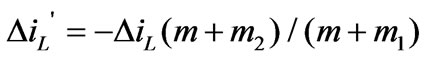
It can be seen that  gets smaller when D < 0.5 (
 ) and the system is stable after a switching period, while
  gets larger when D > 0.5(
 ) and the system unstable after a switching period.
In order to make the system stay stable, the slope com-
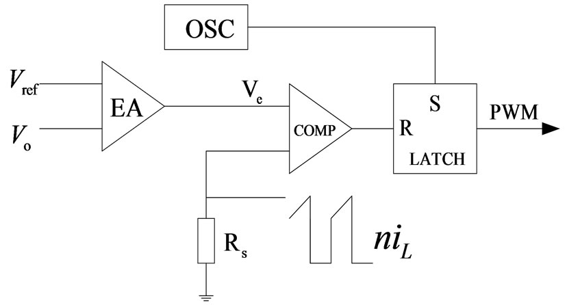
Figure 1. Schematic diagram of peak current control
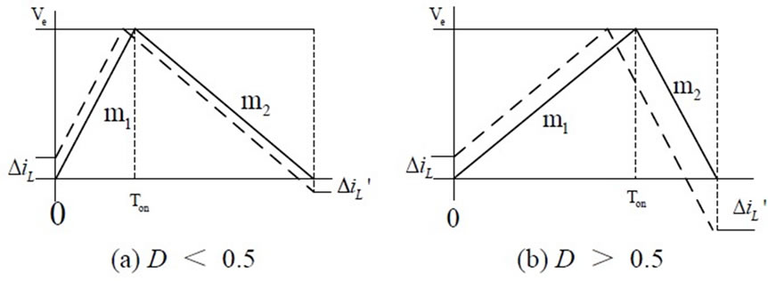
Figure 2. Responses of iL to disturbance on different D
pensation should be employed [4,5]. As usual, there are two methods that can be used to implement the slope compensation: in the first the sum of Ve/RS and slope -m is compared with the current through the inductor, as illustrated in Figure 3(a); in the second the sum of the current of the inductor and slope m is compared with Ve/RS as in Figure 3(b).
Taking Figure 3(a) as example, the response to the current disturbance can be shown in expression (3) after compensation.
 (3)
(3)
It can be concluded that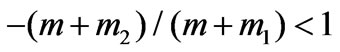 , i.e., the condition of
![]() > −0.5 should be met, because
> −0.5 should be met, because 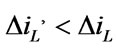 in a stable system.
2.2 Peak Current Protection Issue Caused by Slope Compensation
Based on the above analysis, the slope compensation can make the system controlled by peak current easier to stabilize even though D is greater than 0.5. However, slope compensation causes the maximum current limiting value to vary when the duty cycle changes. This is bad for those systems in which the given voltage and current need to change, such as a plating power supply. Because the duty cycle needs to change in these systems, the switch will bear a heavy burden of current stress. Hence, in order to guarantee switch safety we must choose a highly rated switch, which raises the design cost.
Taking the example of Figure 3(b), the compensation function can be expressed as Equation (4) during the time interval of ton:
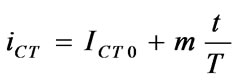 (
( )(4)
)(4)
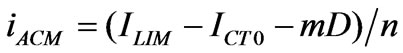
where, iCT is instant compensation value, ICT0 is the minimum of the slope compensation value, and m is the slope rate of the compensation function.
As usual, the maximum value of the sampled current, i.e., over-current-protect point is set as a constant ILIM. Hence, what we limit is the sampled current value after slope compensation, and the actual peak current limiting value should be calculated by expression (5).
 (5)
(5)
where, n is the turn ratio of the current transformer. As can be seen from expression (5), the current limiting value is higher when D is smaller, while the current limiting value is lower when D is larger. It is clear that peak current limiting value differs when D differs, and the current through the inductor can get very high when D is near to zero. Based on this analysis, we know that there is a conflict between safe use and full use of a switch after utilizing slope compensation. The following section will propose a solution to this conflict.
3. Proposed Constant Peak Current Limiting
3.1 Operation Principle
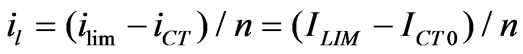
In order to make the limited current value through a switch not to change with duty cycle D, we propose that the current with the same slope as the compensating current should be added to the original current limiting value. Hence, the increment caused by slope compensation should be cancelled out, so the constant peak current limiting value through the inductor can be obtained. The concrete technique is to import the slope compensation waveform in Figure 4 to the maximum current limiting pin of PWM control chip. Thus we can obtain the current limiting value, as seen in Equation (6).
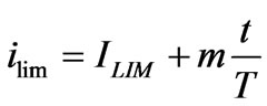 (6)
(6)
Substituting (6) for ILIM in (5), we get (7). Seen from Figure 4 and Expression (7),  is independent of D and only dependent on the initial value of slope compensation and current limiting value, as a result of the fact that constant peak current limiting value has been achieved.

Figure 3. Principle of slope compensation
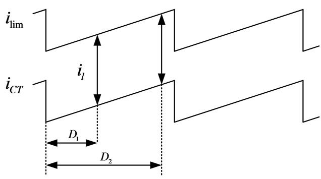
Figure 4. Principle of constant peak current limiting
 (7)
(7)
3.2 Implementation Circuit
Figure 5 shows the schematic circuits of slope compensation accompanying constant peak current limiting. This scheme has been successfully applied to twochokes-interleaving forward converter with UC3846 [6,7]. The slope compensation signal is attained from CT pin of UC3846, which generates saw-tooth waveforms. As seen in Figure 5, the constant peak current limiting signal is also obtained from CT. RP and RT depend upon R3, R4, R5 and RS in the slope compensation circuit. In order to cancel out the effect on current limiting caused by slope compensation, the increments of the two inputs in the comparator should be equal. Considering the threetimes-gain current operator in UC3846, expression (8) is given to determine the resistors Rp and RT.
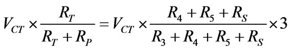 (8)
(8)
4. Experimental Results and Analysis
A dual-forward converter prototype, shown in Figure 6, is built to verify the proposed method [6,7]. The output of the prototype can be regulated from 0 V and 0 A to 6 V and 150 A. The current through the switches or inductor is sensed by a current transformer and the resistor Rs in Figure 5 to achieve peak-current control. The highfrequency power transformer is designed as N1 : N2 = 42 : 1 and the turn ratio of the current transformer for sensing is 1 : 100. Figures 7(a)-(d) show the waveforms of sampled current after slope compensation and voltage waveforms from the current limiting pin corresponding to different values for D.
In Figure 7, CS+ is a waveform after adding slope compensation (corresponding to CS+ in Figure 5). Ilim is the waveform of the current limiting pin (corresponding to Ilim in Figure 5 and in Figure 4). D is the duty-cycle waveform of UC3846. As can be seen from Figure 7, the instant current limiting value rises with the switches conducting time increases, and the slope of its waveforms is the same as that of the slope-compensation current. Hence it can be concluded that the increments added to the two inputs in the comparator of UC3846 are counteracted and constant peak current limiting is accomplished.
Due to the fact that the current ripples through the filter inductor and the magnetic current of power transformer are very small in the application circuit, the average current through thee switches during the on time interval can be considered to approximately equal to their peak current IPK. So we get:
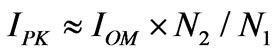 (9)
(9)
where, IOM is the output current limiting value (measured value) at different duty cycles, and IPK is the peak current value (calculated value); these are listed in Table 1.
Figure 8 shows the current limiting values using conventional methods (the current limiting pin being connected to constant voltage) and using the proposed constant-peak-current-limiting method correspondingly. In Figure 8, curve I represents the limiting value in the conventional method, while curve II represents the proposed method in this paper. As is seen from Table 1 and Figure 8, the current limiting value almost stays constant although the duty cycle is different.
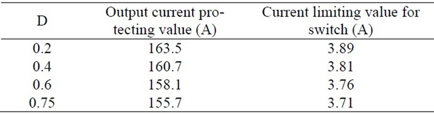
Table1. Peak current limiting value vs. duty cycle
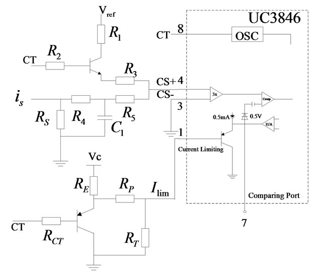
Figure 5. Schematic diagram of slope compensation & constant peak current limiting

Figure 6. Dual-forward converter
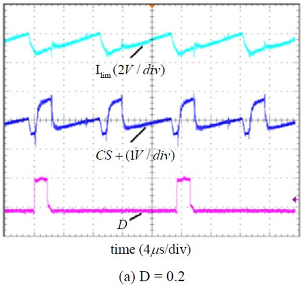

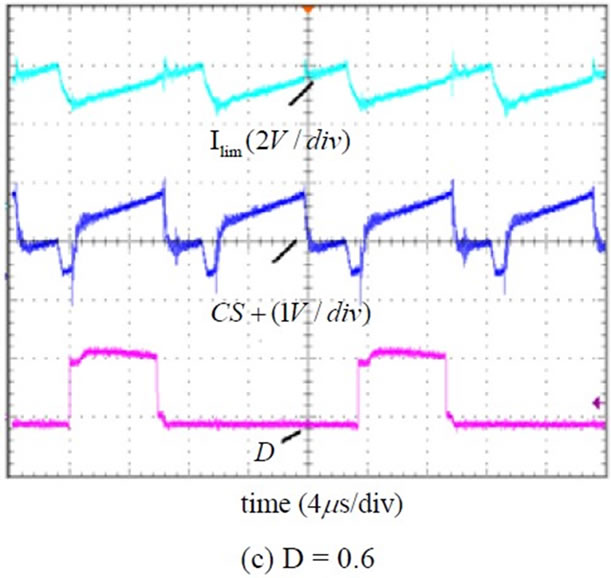

Figure 7. Waveforms of inductor and current limiting pin at different D
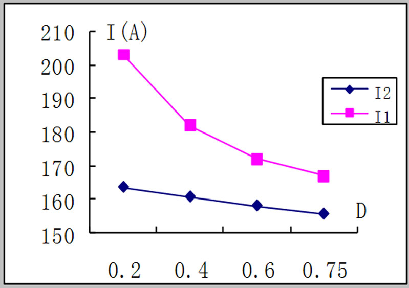
Figure 8. Peak current protecting points (I1-conventional method, I2-proposed method)
However, it seems that the proposed method does not achieve complete constant peak current limiting values; this is because the concerned resistors do not match well and they cannot proportionally change with each other when operation. This can be improved by optimizing RT. Additionally, it is the main reason that the inner PNP transistor’s affection of UC3846 is not considered in light of the expression (8). The PN junction voltage drop influence much more when the duty cycle is small. With regard to this factor, we are braving the storm.
5. Conclusions
The proposed method in this paper implements constantpeak-current-limiting value. The implementing circuits are very simple and easy to accomplish, the additional cost is almost zero, and furthermore the full use of the rated switch can save cost. Next step how to make the current-limiting value complete constant is the aim.
6. Acknowledgments
The research was supported by the University Natural Science Research Plan of Jiangsu Province, P.R. China (05KJD470200).
REFERENCES
- X. Yang and Z. A. Wang, “A Novel Quasi-Constant Hysteretic PWM Current Mode Control Approach,” Transactions of China Electrotechnical Society, Vol. 18, No. 3, 2003, pp. 24-28.
- X. Yan, “Research on Parallel Operation of Current Regulated Inverters,” pH.D Dissertation, Nanjing University of Aeronautics and Astronautics, Nanjing, 1999.
- T. J. Liang and K. C. Tseng, “Analysis of Integrated BoostFlyback Step-Up Converter,” IEE Proceedings on Electronical Power Application, Vol. 152, No. 2, 2005, pp. 217-225.
- G.-M Chen, J.-L Cao and X.-C. Wang, “Design and Implementation of Ramp-Wave Generator in Peak Current Controlled BOOST DC-DC Converter,” Journal of Shanghai University, Natural Science Edition, Vol. 8, 2004, pp. 357-361.
- M. K. Kazimierczuk, “Transfer Function of Current Modulator in PWM Converters with Current-Mode Control,” IEEE Transactions on Circuits and Systems, Vol. 47, No. 9, 2000, pp. 1407-1412.
- F. Han, D. H. Xu and M. Matsui, “A Novel ZVT Circuit for Interleaving Two-Transistor forward Converter,” Proceeding of IEEE APEC, 2000, pp. 754-759.
- J. Li and Y. Xing “Research on Variable Low Voltage High Current DC-DC Converter,” The Eighth International Conference on Electrical Machines and System, 2005, pp. 118-129.