Journal of Electromagnetic Analysis and Applications
Vol. 1 No. 3 (2009) , Article ID: 723 , 7 pages DOI:10.4236/jemaa.2009.13022
Rotating Capacitor and a Transient Electric Network
1The Pennsylvania State University, York, PA 17403; 2Nenette Sarafian, Hershey Medical Center.
Emall: 1has2@psu.edu, 2nsarafian@hmc.psu.edu
Received May 16th, 2009; revised July 10th, 2009; accepted July 16th, 2009.
Keywords: RC-Series Transient Electric Network, Rotating Parallel-Plate Capacitor, Mathematica
ABSTRACT
This paper presents a rotating parallel-plate capacitor; one of the plates is assumed to turn about the common vertical axis through the centers of the square plates. Viewing the problem from a purely geometrical point of view, we evaluate the overlapping area of the plates as a function of the rotated angle. We then envision the rotation as being a mechanical continuous process. We consider two different rotation mechanisms: a uniform rotation with a constant angular velocity and, a rotation with a constant angular acceleration—we then evaluate the overlapping area as a continuous function of time. From the electrostatic point of view, the time-dependent overlapping area of the plates implies a time-dependent capacitor. Such a variable, a time-dependent capacitor has never been reported in literature. We insert this capacitor into a series with a resistor, forming a RC circuit. We analyze the characteristics of charging and discharging scenarios on two different parallel tracks. On the first track we drive the circuit with a DC power supply. We study the implications of the rotation modes. We compare the response of each case to the corresponding traditional constant capacitor of an equivalent RC circuit; the quantified results are intuitively just. On the second track, we drive the circuit with an AC source. Similar to the analysis of the first track, we generate the relevant electrical characteristics. In the latter case, we also analyze the sensitivity of the response of the circuit with respect to the frequency of the source. The analyses of the circuits encounter nontrivial differential equations. We utilize Mathematica [1] to solve these equations.
1. Introduction and Motivation
It is a far-fetched concept to think about a conventional transient electrical circuit and incorporate its signal characteristics into a discrete and abstract geometry problem. The authors have even taken the initiative one step further relating these two basic concepts to kinematics. This article shows how these three discrete concepts are brought together and molded into one coherent and unique research project. A thorough literature search of the standard undergraduate and graduate physics texts and reference books reveals the lack of any similar analysis [2]. In the course of quantifying the signal analysis we encounter challenging nontrivial differential equations. In our experience in analyzing comparable technical problems it is proven that Mathematica is the most convenient and efficient tool of choice. Utilizing its coherent and simultaneously applicable symbolic, numeric and graphic features assists the authors to focus on the physics issues of interest. Mathematica’s tools also suppress the challenges of developing basic computer programs from the ground-up.
The flow chart of this article including the Introduction contains three additional sections. In Section I, as a pure geometry problem we apply Mathematica to evaluate the overlapping area of the two rotated squares about their common vertical axis. We then incorporate the rotational kinematics and view the rotation as a mechanical process and consider two different scenarios: 1) a symmetric, uniform rotation; and 2) an asymmetric, accelerated rotation. In Section 3, we view the overlapping squares as being two parallel metallic plates that are separated by a gap forming a parallel-plate capacitor. Following the traditional textbook approach [2], we assume the gap is much smaller than the dimensions of the square. This suppresses the fringe effects. Since the area of the overlapping plates evaluates the capacitance of the capacitor, the rotating plates make the capacitor variable. Technical literatures, particularly Mathematica-based reference books such as [3] contain a wealth of references within themselves, yet lack our novel view. It is the ultimate objective of this project to analyze the electric signal characteristic response of the electrical network to the kinematics of the rotating plates. Specifically, in this article, we address the modifications of the characteristic signal responses of the electrical circuits composed of a resistor connected in a series with our designed, timedependent capacitor. In particular, we analyze the characteristics of the RC circuits driven with DC as well as AC sources. The third and conclusion section, in conjunction with our recent analysis, descriptively outlines the results of more generalized cases.
2. Analysis
2.1 Geometry
Figure 1 shows two identical overlapping squares. The bottom square designated with non-prime vertices is fastened to the xy coordinate system. The top square, designated with prime vertices is rotated counter clockwise about the common vertical axis through the common origin O by an angle θ. The squares have the side length of L and the rotation angle θ is the angle between the semi diagonals  and
and 
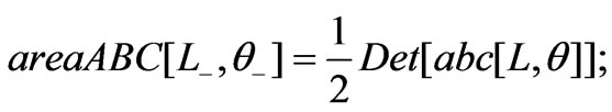
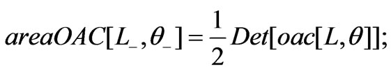
To evaluate the overlapping area of these two squares we evaluate the area of trapezoid oabco; the overlapping area then equals four times the latter. The intersecting points of the rotated sides of the top square with the sides of the bottom one are labeled a, b, and c. Utilizing the coordinates of these points, the area of the trapezoid is the sum of the areas of two triangles abc, and oac.
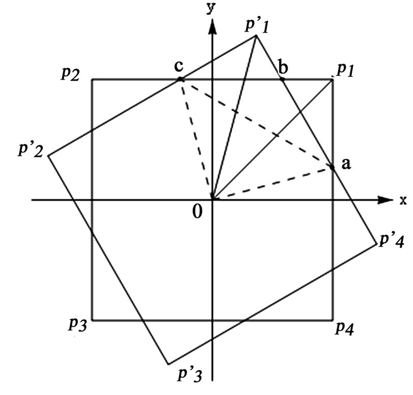
Figure 1. Display of two rotated squares. The bottom square is fastened to the xy coordinate system, the top square is rotated counter clockwise by θ radian
To evaluate the coordinates of a, b, and c we write the equations for the slanted lines,  and
and  and intersect them with the sides of the bottom square. Intersection of the former with the
  and
and  gives the coordinates of a and b, respectively. Similarly, the intersection of the latter with
  yields the coordinates of c. Theses are:
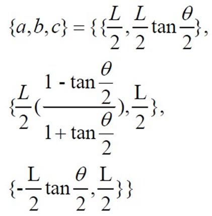 (1)
(1)
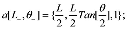
To evaluate the areas of the needed triangles, we convert the above coordinates into Mathematica code. The inserted 1's in the third position of the coordinates of the origin and the intersecting points are for further calculations.
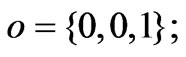
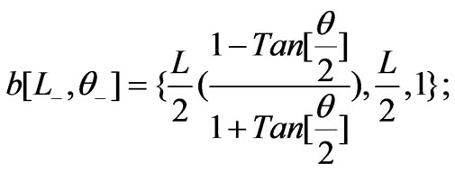
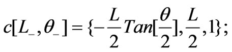
We define two auxiliary lists,

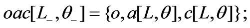
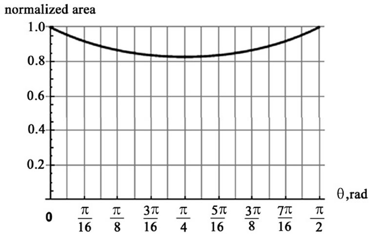
Figure 2. The normalized values of the overlapping area of the squares as a function of the rotation angle q
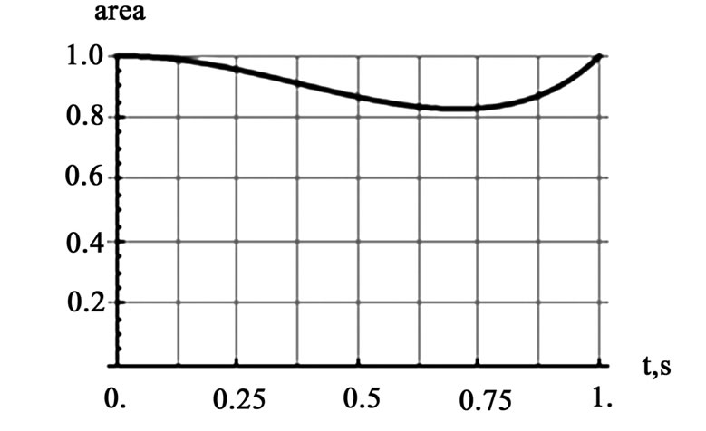
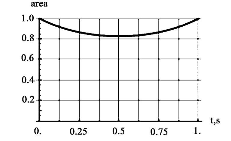
Figure 3. The graphs are the normalized values of the overlapping areas for: a) a uniform rotation with w=p/2rad/s, (the left graph) and b) a uniform angular acceleration with a=p rad/s2 (the right graph)
The needed areas are,
 therefore,

We divide the value of the overlapping area by the area of the square, L2, and plot its normalized values as a function of the rotation angle q. Figure 2 shows the normalized area begins and ends at the same values. The value of the area after a p/4 radian turn drops to about 83% of the maximum value. The plot as one anticipates is symmetric about p/4. The Mathematica codes followPlot[4 areaOABCO[L, q]/L2,{ p,0, p/2},Ticks®{Range
[0, p/2, p/16],Automatic},PlotRange®{0,1},AxesLabel
{"q ,rad","normalizedarea"},GridLines®{Range[0, p/2p/32],Automatic}];
2.2 Modes of Mechanical Rotations
In this section we extend the analysis of Subsection 2.1. Here, instead of viewing the rotation as being a discrete and purely geometrical concept, we view it as a kinematic process. We set the rotation angle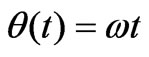 ; that is, we introduce the continuous time parameter t. For
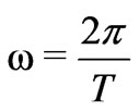
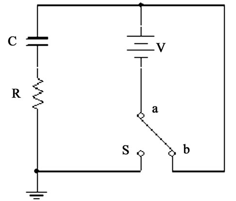
Figure 4. The schematics of a DC driven RC circuit. Throwing the DPDT switch onto  charges the capacitor, while throwing the switch onto
  discharges the charged capacitor
with the period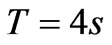 , we explore the uniform rotation. For an asymmetrical case, we consider a rotation with a constant angular acceleration. According, for the latter, to rotate the square by 90° in one second we set
 ,with
,with . The corresponding normalized overlapping areas are displayed in Figure 3.
The Mathematica codes followsUniformRotation = Plot [4 areaOABCO [L,q]/L2/.q®
p/2t,{t,0,1},Ticks®{Range[0,1,1/8],Automatic}PlotRange®{0,1},AxesLbel®{"t,s","area"},GridLines ®
{Range[0,1,1/16], Automatic}];
AcceleratedRotation=Plot [4areaOABCO[L,q]/L2/.q
® p/2t2,{t,0,1},Ticks®{Range[0,1,1/8],Automatic}PlotRange®{0,1},AxesLabel® {"t,s","area"}, GridLines
® {Range[0,1,1/16], Automatic}];
Show [GraphicsArray[{UniformRotation, AcceleratedRotation}]];
3. Electrical Networks
Now we consider a RC series circuit. One such circuit driven by a DC power supply is shown in Figure 4. The circuit is composed of two loops. Throwing the DPDT (Double-Pole Double-Throw) switch to  position charges the capacitor, while setting the switch to a
  discharges the charged capacitor.
As we pointed out in the Introduction, in this section we view the overlapping squares as being two parallel metallic plates that are separated by a gap forming a parallel-plate capacitor. Since the capacitance of a parallel-plate capacitor is in proportion to the overlapping area of the plates, the continuous rotation of the plates makes the capacitor time-dependent. It is the objective of this section to analyze the characteristics of the electric response of one such time-dependent capacitor in the charging and discharging processes.
3.1 Characteristics of Charging and Discharging a DC Driven RC Circuit with Time-Dpendent Uniformly Rotating Plates
For the charging process we apply Kirchhoff circuit law [2], this gives
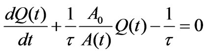 (2)
(2)
For the sake of convenience, we assume V C0=1, where C0 is the capacitance of the parallel-plate with the plates completely overlapped, Q(t) and A(t) are the capacitor's charge and the overlapping area at time t, respectively; A0 is the area of one of the squares; and  is the time-constant of the circuit. For a constant, time independent capacitor,
  , and Equation (2) yields the standard solution
 . In this equation the maximum charge is normalized to unity.
For the rotating plates, however, Equation (2) does not have an analytic solution. We apply Mathematica NDSolve along with an appropriate initial condition and solve the equation numerically—this yields Q(t). Graphically, we compare its characteristics vs. the characteristics of an equivalent RC circuit, this is shown Figure 5. The Mathematica code follows
solQUniformRotation=With[{t=1./6}, NDSolve[{Evaluate[(Q'[t]+1/t L2/(4 areaOABCO[L,q]/.q®p/2 t) Q[t] -1/t)]==0,Q[0]==0},Q[t],{t,0,1}]];
s34=Plot[{1- /.t®1./6,Q [t]/.solQUniformRotation},{t,0,1},PlotStyle®{GrayLevel[0],GrayLevel [0.5]}, AxesLabel®{"t,sec","Q"}, PlotLabel->"Charging",PlotRange®{Automatic,{0,1.02}}, GridLines® {Range [0,1, 1/8],Automatic}];
Similarly, we analyze the characteristics of the discharging process. Equation (2) for the corresponding discharging process is,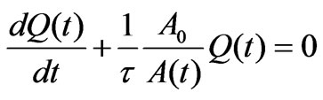 . This equation for a constant, time independent capacitor,
  , yields
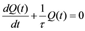 , and gives
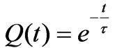 . For the rotating capacitor, however, its solution is
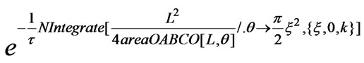
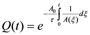 . To solve the latter we apply Mathematica NIntegrate. This yields the needed values. The results are displayed in Figure 5. The Mathematica code followstable C0Discharge=Table [{t,N[
 /.t®1./6]}, {t,0,1, 1/16}]; listC0Discharge=ListPlot [tableC0D ischarge, PlotStyle®{PointSize[0.02], GrayLevel [0]}, GridLines-> {Range [0,1,1/8], Automatic}, Ticks ®{R ange [0,1,1/8], Automatic}];
tableCtUniformDischarge=Table[{k,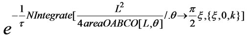 /.t®1./6},{k,0,1,1/16}];
listCtUniformDischarge=ListPlot[tableCtUniformDischarge,PlotStyle®{PointSize[0.02],GrayLevel[0.5]}];
s12=Show[{listC0Discharge,listCtUniformDischarge}A-xesLbel®{"t,sec","Q"},PlotRange®{Automatic,{0.1.02}},Plot Label->"Dis charging"];
Show[GraphicsArray[{s34,s12,UniformRotation}],ImageSize®600];
It is interesting to note that the charging and discharging signals respond differently to the time-varying ca pacitors; the impact of the time-dependent capacitor is more pronounced for the former. Moreover, for the value of the chosen time-constant of the circuit, t=1/6 s, although the time-independent capacitor reaches its plateau within one second, the variable capacitor requires a longer time span.
3.2 Characteristics of Charging and Discharging DC Driven RC Circuit with Time-Dependent Accelerated Rotating Plates
One may comfortably also apply the analysis of Subsection 3.1 to generate the characteristic curves associated with the uniformly accelerated rotating plates. The Mathematica codes may easily be modified to yield the needed information. The codes along with the associated graphic outputs are:
solQAcceleratedRotation=With [{t=1./6},NDSolve [{Evaluate [(Q'[t]+1/tL2/(4areaOABCO [L,q]/.q®p/2 t2) Q [t]-1/t)]==0,Q[0]==0},Q[t],{t,0,1}]];
s56=Plot[{1- /.t®1./6,Q[t]/.solQAcceleratedRotation},{t,0,1},PlotStyle®{Hue[0.7],{Dashing[{0.02}], GrayLevel[0.5]}},AxesLabel®{"t,sec","Q"},PlotLabel->
"Charging",PlotRange®{Automatic,{0,1.02}},GridLines
®{Range[0,1,1/8],Autmatic},Ticks®{Range[0,1,1/8],A utomatic}];
tableCtAcceleratedDischarge=Table[{k,
 /.t®1./6},{k,0,1,1/16}];

Figure 5. Display of charging (the left graph) and discharging (the right graph) signals of uniformly rotating plates. In each graph the black and the gray curves/dots are the signals of the time-independent and time dependent capacitors, respectively. For a comprehensive understanding these graphs are to be incorporated with the left graph of Figure 3
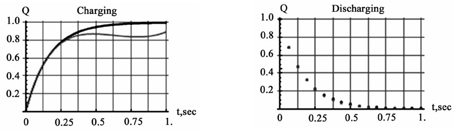
Figure 6. Display of charging (the left graph) and discharging (the right graph) signals of uniformly accelerated plates. The color codes are the same as Figure 5. For a comprehensive understanding these graphs are to be incorporated with the right graph of Figure 3
listCtAcceleratedDischarge=ListPlot[tableCtAcceleratedDischarge,PlotStyle®{PointSize[0.02],GrayLevel [0.5]},GridLines®{Range[0,1,1/8],Automatic},Ticks ®{Range [0,1,1/8],Automatic}];
s78=Show[{listC0Discharge,listCtAcceleratedDischarge},AxesLabel®{"t,sec","Q"},PlotRange®{Automatic,{0.,1.02}},PlotLabel->"Discharging"];
Show[GraphicsArray[{s56,s78,AcceleratedRotation}]];
To form an opinion about the characteristics of the charging signal for the variable capacitor, one needs to view it together with the far right graph of Figure 3. The rotating plates in this case are accelerated, meaning that for identical time intervals, the overlapping area at the beginning is greater than the overlapping area at the end of the interval. The effects of the asymmetrical rotation are most clearly visible at the tail of the signal. Similar to the uniform rotation (see the lift graph of Figure 5) the impact of the non-uniform rotation for the discharge signal is negligible.
3.3 Characteristics of Charging and Discharging an AC Driven RC Circuit with Time Dependent Capacitor
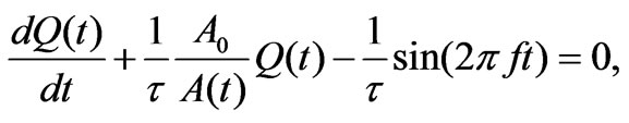
In this section we analyze the charging and the discharging characteristics of an RC series circuit driven with an AC source. Schematically speaking, this implies in Figure 4 we replace the DC power supply with an AC source. For this circuit, Kirchhoff's law yields
 (3)
(3)
In this equation f is the frequency of the signal and the voltage amplitude is set to one volt.
Equation (3) is a non-trivial differential equation. To solve this equation, we apply NDSolve along with the corresponding initial condition. The response of the circuit is compared to the equivalent circuit with a constant capacitor. The Mathematica code followssolQac=NDSolve[{Evaluate[(Qac'[t]+1/t L2/L2 Qac[t] -1/t Sin[2p f t])/.{t®1./6,f®0.6}]==0,Qac[0]==0},Qac[t], {t,0,1}];
plotQac=Plot[Qac[t]/.solQac,{t,0,1},PlotStyle®GrayLevel[0],AxesLabel®{"t,sec","Q"},PlotLabel®AC Driver, DisplayFunction®Identity];
solQactUniform Rotation=NDSolve [{Evaluate [(Qact' [t]+1/tL2/(4area OABCO [L,q]/.q®p/2t) Qact[t]-1/t Sin- [2pft])/.{t®1./6,f®0.6}]==0,Qact[0]==0},Qact[t], {t,0,1}];
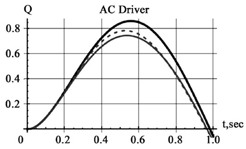
Figure 7. Display of the charge on the capacitor vs. time. The solid black curve is the signal of the time-independent capacitor. The solid and dashed gray curves are the signals of the time-dependent capacitors for uniform and accelerated rotations, respectively
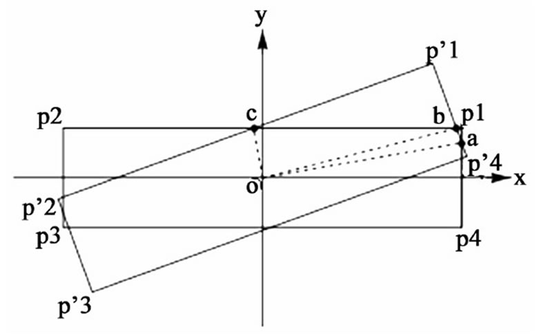
Figure 8. Display of two rotated rectangles. The bottom rectangle is fastened to the xy coordinate system; the top rectangle is rotated counter clockwise by q radian
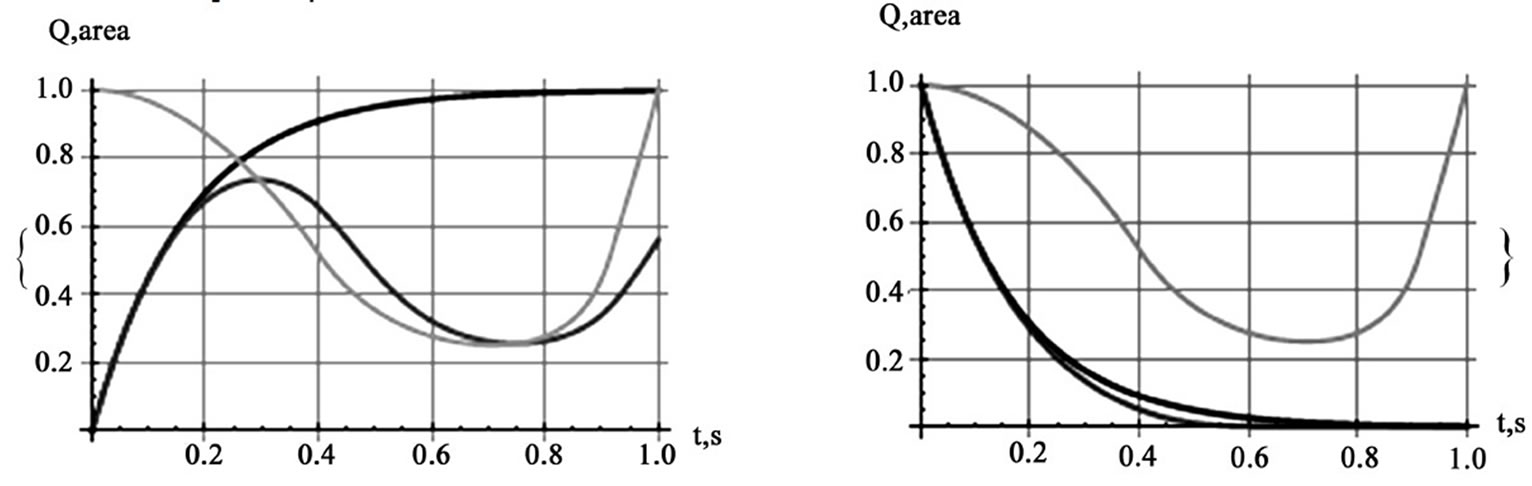
Figure 9. Display of charging (the left graph) and discharging (the right graph) signals of uniformly accelerated plates. In both graphs the light gray curves are the overlapping area; the black curves are the time-independent capacitor’s signals, while the medium gray curves are the corresponding time-dependent signals
plotQactUniformRotation=Plot[Qact[t]/.solQact UniformRotion,{t,0,1},PlotStyle®GrayLevel[0.5],AxesLabel
® {"t,sec","Q"}, PlotLabel®AC Driver];solQact Accelerated Rotation=NDSolve [{Evaluate [(Qact'[t]+1/t L2/(4 areaOABCO[L,q]/.q®p/2 t2) Qact[t]-1/t Sin[2p f t])/. {t® 1./6,f®0.6}]==0,Qact[0]==0},Qact[t],{t,0,1}];
plotQactAcceleraedRotion=Plot[Qact[t]/.olQactAcceleratedRotation,{t,0,1},PloStyle®{Dashing[{0.02}],GrayLevel[0.5]},AxesLabel®{"t,sec","Q"},PlotLabel®AC Driver];Show[plotQac,plotQactUniformRotation,plotQactAcceleratedRotation,ImageSize®300];
Utilizing the Mathematica code, one may analyze the frequency sensitivity response of the circuit. As the result of one such analysis, we observe that the differences between the time-independent vs. the time-dependent signals are more pronounced with a frequency domain of less than 1 Hz.
4. Conclusions
Since the inception of the first version of this project, “the square plates” the authors have extended the scope of their investigation. The idea of rotating the plates of a parallel-plate squared capacitor is sound; however, as we addressed in the aforementioned text the area of the overlapping plates at its best is reduced to only 83% of the maximum area. The square geometry puts a limit to the overlapping area of the rotated plates, limiting the impact of the corresponding time-dependent capacitor on the characteristic signals. To enhance the impact, a potential remedy is to replace the square plates with less symmetric flat objects, e.g. a rectilinear or a curvilinear shape such as a rectangle or an ellipse, respectively. For the rectangular plates, for instance, by adjusting the length and the width of the rectangle one is able to reduce the value of the overlapping area at will. This, in turn, more effectively impacts the capacitance of the time-dependent capacitor. The unevenness of the symmetry of the rectangle about its perpendicular axis through the center of the rectangle results a host of mathematical challenges. The evaluation of the overlapping area of the rotated rectangles, contrary to the square plate case, is composed of three different configurations; one such configuration is shown in Figure 8. The
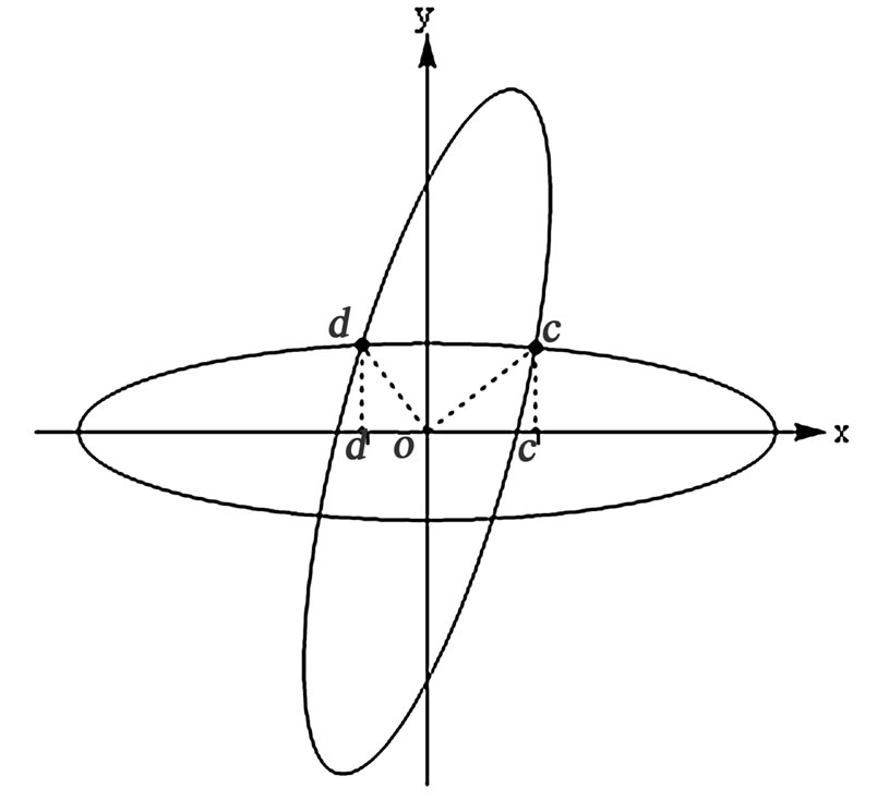
Figure 10. Display of two rotated ellipses. The bottom ellipse is fastened to the xy coordinate system; the top ellipse is rotated counter clockwise by q radian
other two configurations are shown in [4]. The characteristics of the associated charging and discharging signals for uniformly accelerated plates with dimensions L/W = 8/2 are shown in Figure 9. The changes in the characteristic signals in comparison to the counterparts, Figure 6, are drastic. Mathematical analysis and the detailed solution of the differential equations describing the intricacies of the rectangular plates are discussed in length in [4].
The authors also have extended their investigations to consider curvilinear plates, such as a pair of elliptical plates. Figure 10 is borrowed from [5]. Mathematical and detailed calculations resulting in the value of the overlapping area of the plates are discussed in [5]. Reference [5] also includes the characteristic charging and discharging signals as well. Given the comparable dimensions of the rectangles in [4] vs. the dimensions of the ellipses in [5] we reasoned the similarity of their output signals. To avoid the repetition of showing their similar transient electric signals we omit displaying the latter. An interested reader is encouraged to review reference [5].
As indicated in the Introduction, the authors have proposed a unique research project that has brought together three different subject areas: Geometry, Mechanics, and Electrical Network. Mathematica, with its flexible and easy to use intricacies, is chosen as the ideal tool to analyze the project and address the “what-if” scenarios. As pointed out in the text, some of the derived results are intuitively just. And for the hard to predict cases, we applied Mathematica to analyze the problem. As an openended question and research oriented project, one may attempt to modify the presented analysis along with the accompanied codes to investigate the response of parallel RC circuits. It would also be complimentary to our theoretical analysis to manufacture a rotating capacitor to supplement the experimental data.
REFERENCES
- S. Wolfram, “The mathematica book,” 5th Ed., Cambridge University Publication, 2003.
- D. Halliday, R. Resnick, and J. Walker, “Fundamentals of physics extended,” 8th Ed, John Wiley and Sons, 2007; J. D. Jackson, “Classical Electrodynamics”, 3rd Ed, John Wiley and Sons, 1998.
- M. Trott, “The mathematica guidebook for graphics,” Springer, 2004.
- H. Sarafian, “Rotating rectangular parallel-plate capacitor and a transient electric circuit”, International Mathematica Symposium, IMS, 2008.
- H. Sarafian, “Rotating elliptical parallel-plate capacitor and a transient electric circuit”, International Conference on Computational Science and its Application, ICCSA’08, pp. 291–296, Springer 2008.