Int'l J. of Communications, Network and System Sciences
Vol.6 No.1(2013), Article ID:27445,11 pages DOI:10.4236/ijcns.2013.61002
Hybrid Real-Time and Preset Processing for Indoor Radio Geo-Location in Dense Multipath Environments
Division of Physics, Electrical and Computer Engineering, Yokohama National University, Yokohama, Japan
Email: *kabir@kohnolab.dnj.ynu.ac.jp
Received October 22, 2012; revised November 24, 2012; accepted December 7, 2012
Keywords: UWB Signaling; Node Localization; Target Tracking; Fingerprinting; TOA; NLOS
ABSTRACT
The existence of various geo-location applications and their accuracy requirements enhance the necessities for suitable processing techniques to solve the indoor geo-location problems. Since, Impulse Radio Ultra-Wideband (IR-UWB) signals have very short duration pulses; they can provide very accurate ranging and geo-location capability in short range indoor radio propagation environments. Our research puts emphasis on indoor geo-location using UWB signaling considering both of non line-of-sight (NLOS) and LOS radio propagation environments. In this paper, we introduce and investigate a noble approach which makes a hybrid combination of Channel Impulse Response (CIR)-based fingerprinting (FP) method with polygonal arrangement of reference nodes (or tags) and an iterative-TOA based real-time geo-location method using UWB signaling for wireless ad hoc networks. The proposed hybrid approach assures significant improvement in positioning accuracy compared to TOA only, FP only and conventional iterative-TOA geolocation methods by mitigating NLOS errors effectively in the indoor environment. Besides, this hybrid approach minimizes the calculation complexity of the FP method while maintaining improved geo-location accuracy in the dense multipath propagation environment.
1. Introduction
The appropriate and highly precise geo-location in indoor wireless networks could provide more interesting location based services in many domains. Fingerprinting type of pre-calculation based geo-location is one of the most popular approaches for precise geo-location, since it is more applicable to complex indoor environments than other approaches. However, the high time resolution characteristic of UWB signal makes time of arrival (TOA) or time difference of arrival (TDOA) based real time approach a good choice for indoor geo-location using UWB signals.
In our research, we introduce and investigate a noble geo-location approach which makes a hybrid combination of Channel Impulse Response (CIR)-based FP method with polygonal arrangement (which will be discussed in a later Chapter) of reference nodes and an iterative-TOA based real-time method using UWB signaling in the both of non line-of-sight (NLOS) and LOS radio propagation environments. This hybrid approach minimizes the calculation complexity of the FP method while maintaining improved geo-location accuracy. Moreover, we employ a deterministic wave propagation model based on Ray Tracing technique to predict realistic indoor radio coverage and CIRs. This hybrid solution for geo-location can be implemented in wireless ad hoc networks such as PAN, BAN, and RFID as well as for localization of wireless sensor nodes.
This paper is the continuation of our previously published paper [1]. In the previous paper, we only concentrate on the successful implementations of our proposed hybrid method in an indoor radio propagation environment such as a typical office room. Besides, we limited our discussion on the positioning performances of FP and proposed hybrid localization considering various NLOS incidences experienced by access points (AP)s. Moreover, the detailed mathematical analysis of computational complexity of the proposed hybrid method was beyond the scope of that paper.
In this paper we deeply analyze the performance of FP and hybrid algorithms for the cases with LOS as well as the worst cases of NLOS situations. Besides, the definition of NLOS rate used in this paper is different from that of previous paper. Therefore, more detail analysis for NLOS cases has been made in the present paper. We also provide the detailed mathematical analysis of computational complexity of the proposed hybrid method. Therefore it is possible to evaluate the tradeoff between calculation complexity and geo-location accuracy of the proposed method. By analyzing this trade-off quantitatively, the optimum size of polygon for reference tags arrangement can be determined for minimizing calculation complexity of the proposed method.
The remaining of the paper is organized as follows: Chapter 2 provides the brief reviews of related works. Chapter 3 illustrates the preparations for our proposal for hybrid positioning algorithm. The details of our proposal for hybrid algorithm are provided in Chapter 4. Chapter 5 analyses the model’s performance using computer simulations. Finally, a brief conclusion is made in Chapter 6.
2. Related Works
Multi-path radio wave propagation encumbers accurate calculation of the distance between the transmitter and the receiver in the indoor geo-location approaches. Many authors and research groups have proposed techniques to compensate for the inaccuracies due to multipath and other radio channel impairments.
The Wi-Fi based CRICKET Location-Support System [2] is well-known in indoor geo-location; however it depends on deployed infrastructure like RF and ultra sonic beacons. The RADAR [3] system proposed signal strength based fingerprinting (FP) approach for indoor localization and tracking. Although the system requires extensive measurements and calibration, the achieved localization performance is not satisfactory. Moreover, their model does not fully capture the multipath phenomenon as it only considers LOS path.
It is well-known that the presence of non line-of-sight (NLOS) path in the multipath propagation environment causes positive bias for ranging estimation, which leads to severe performance degradation of traditional trilateration based geolocation techniques. S.G. Razul et al. [4] proposes a Bayesian method to mitigate the NLOS errors in location estimation of a single moving sensor. W. Ke et al. [5] and C.-D. Wann [6] introduce geo-location algorithms for the mixed LOS and NLOS environments, which utilizes extended Kalman filter (EKF) to reduce the NLOS errors. Moreover, particle filter based TDOA positioning is introduced for NLOS scenarios by Boccadoro et al. [7]. S. Dayekh et al. [8] innovates a CIRbased positioning technique within a cooperative memory-assisted approach that exploits both the temporal and spatial diversities of the collected fingerprints. Whereas, G. Ding et al. [9] proposes a cooperative localization algorithm to mitigate NLOS errors, which combines TOA/AOA measurements of all identified LOS base station (BS)-mobile station (MS) links.
Besides above approaches, to achieve higher accuracy in signal source geo-location, many conventional iterative methods like Gauss-Newton, Steepest Descent, Levenberg-Marquardt are proposed in conjunction with TOA or TDOA method for mitigating NLOS errors. Among them, to maintain the higher accuracy and low complexity, the Levenberg-Marquardt is the most suitable to estimate a mobile location among the iterative methods, reported in C. Mensing and S. Plass [10]. Moreover, these iterative methods require initial positioning guesses. If the guesses are not accurate, the convergence problem may occur. Alternately, a non-iterative geo-location method can provide good initial positions for an iterative geo-location method. In D. Akbarov et al. [11], a hybrid combination of pattern matching (PM) and TDOA geolocation methods is proposed for CDMA network. While, their method has low accuracy in the indoor environment where GPS signal is not satisfactory.
However, our research puts emphasis on indoor geolocation using UWB signaling considering both of LOS and NLOS conditions for wireless ad hoc networks such as PAN, BAN, and RFID as well as wireless sensor nodes localization. Our hybrid geo-location approach combines Channel Impulse Response (CIR)-based FP method with polygonal arrangement of training nodes and an iterative-TOA based real-time methods. Moreover, this approach minimizes the calculation complexity of the FP method while maintaining improved geo-location accuracy.
3. Preparations for Our Proposal for Hybrid Positioning Algorithm
Before introducing our hybrid positioning algorithm the following two sections are the necessary preparations for our proposal. Section 3.1 discusses and proposes a deterministic channel model constructed by using Ray Tracing technique for indoor radio wave propagation. Then, our proposal for the CIR-based FP geo-location approach with polygonal arrangement of reference nodes (or tags) for an indoor propagation environment is explained in Section 3.2.
3.1. Deterministic Channel Model for Indoor Radio Wave Propagation
We consider a typical well-furnished office room that provides an efficient means of simulating a short range indoor UWB channel. Due to reflection, transmission, refraction, and diffraction by obstacles signal propagation suffers from severe multipath effects in an indoor environment [12]. In order to predict the accurate indoor radio coverage and channel impulse response we consider a deterministic (site-specific) propagation modeling technique, called Ray Tracing (RT). The RT technique utilizes the knowledge of the locations and electromagnetic properties of indoor objects, is used to predict path loss, time invariant impulse response, and the RMS delay spread [12,13].
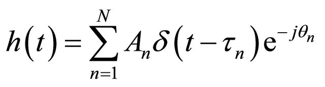
A general model of band-limited complex channel impulse response (CIR) is expressed as [14]:
 (1)
(1)
where, An is the path attenuation, τn is the time delay of the nth path, δ is the Dirac delta function, θn is the phase of the nth path. For the implementation of this model, it is necessary to identify the amplitudes, time delay and phases of the N number of components of the response.
We employed the RT technique to identify the components of the above mentioned channel model. RT technique follows the ray launching approach (based on geometrical optics), which involves a number of rays launched uniformly in space around the transmitter antenna (Figure 1). Each ray is traced until it reaches the receiver or its amplitude falls below a specified limit. In our model, the specular reflections and transmissions are considered while diffraction and scattering are neglected, so that every wave component traverses one of more free space propagation paths between the transmitter and the receiver.
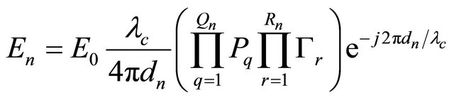
The complex electric field incident at the receiver due to the nth impinging ray can be represented as:
 (2)
(2)
where:
E0: transmitted electric field;
λc: wave length correspond to center frequency;
dn: propagation path length of nth ray;
Rn: number of reflections of nth ray;
Qn: number of penetrations of nth ray;
Γr: coefficient of rth reflection of nth ray;
Pq: coefficient of qth penetration of nth ray.
In Equation (2), the term  is the free space pathloss, the exponential term
  represents phase offsets due to pathlength dn, assuming omni-directional antennas where the azimuthal-plane antenna gains have been ignored for simplicity.
3.2. Proposed CIR Based FP Positioning Approach for Indoor Environment
The contents of this section are the preparations for the hybrid algorithm described in Chapter 4.
The CIR-based FP positioning, is also known as pattern matching technique, is especially suited for positioning under dense multipath conditions [15]. This technique consists of two phases:
1) In the training phase, location signatures (finger-
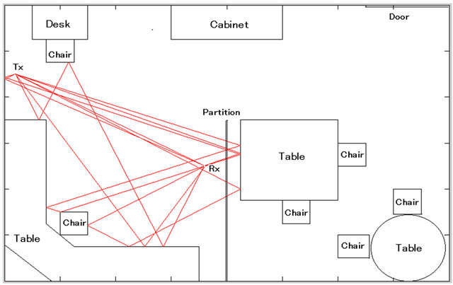
Figure 1. Ray tracing for indoor propagation modeling.
prints) based on the received signal’s CIRs’ are measured by several access points (APs) for various reference locations of nodes in a region to construct a fingerprinting database.
2) In the positioning phase, the run time estimation of node’s location is performed by correlating the CIRs’ of received signal with the fingerprints stored in the database.
Generally, the FP technique requires exhaustive calculations for fingerprinting pattern matching as well as creating a database for storing the location fingerprints (signatures). Therefore, the computational complexity in the FP technique depends greatly on the size of the fingerprinting database employed in pattern matching. As the fingerprints of the reference nodes constitute a database, the larger the number of reference nodes the larger the size of the fingerprinting database needed to cover the whole area, but employing a smaller number of reference nodes reduces the computational complexity, although it will not provide a good accuracy in positioning. In order to combat this positioning constraint we introduce a new idea to optimize the number of reference nodes to cover the whole area as well as to generate a fingerprinting database of optimum size.
In our new idea, we arrange the reference nodes in the room to form polygon shapes (as shown in Figures 2 and 3) instead of deploying them in a scattered way. The number of reference nodes required to cover the whole area depends on the size and quantity of such polygons. Similarly, the size of fingerprinting database also depends on the size of the polygons. Therefore, the optimum polygon size will reduce the computational complexity in fingerprinting pattern matching to a reasonable level while maintaining a certain degree of positioning accuracy in the FP method, so the main idea of arranging reference nodes (or tags) to form polygons is to reduce unnecessary deployment of reference nodes which increase the size of the fingerprinting database. Moreover, by varying the size of such polygons we can vary the size of the fingerprinting database as well as the complexity
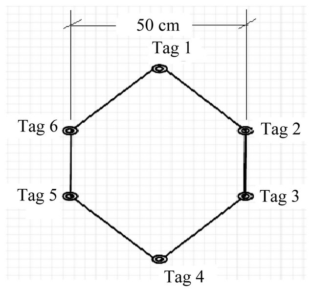
Figure 2. Size of polygon.
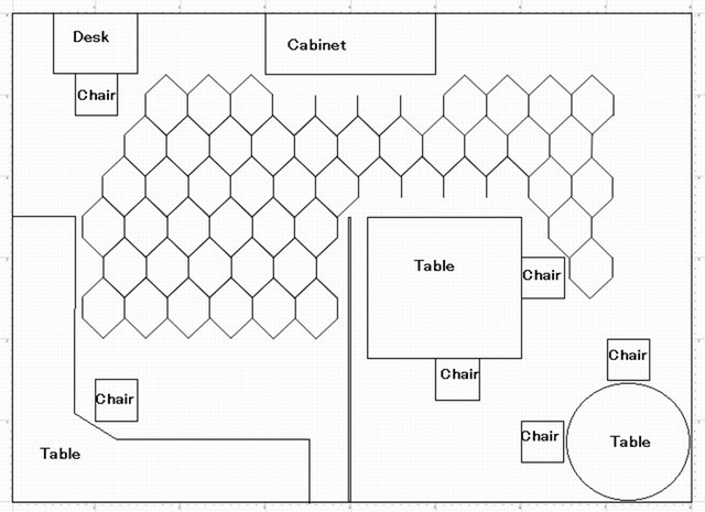
Figure 3. Arrangements of reference nodes in the room forming polygonal shapes.
of the FP method calculations.
In the training phase of the FP method, signatures (fingerprints) h(l,t) are estimated and recorded for various reference locations , where
  is the region of interest. Location of a node (or, tag) in 2D horizontal plane is defined as l(x,y) in Cartesian coordinates.
In the positioning phase, an estimate  of the true instantaneous position
 , is obtained by using the corresponding instantaneous estimated CIR,
 . This estimated CIR is corrupted by channel noise.
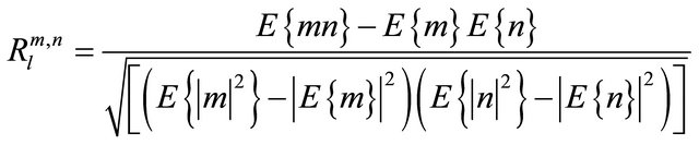
For,  and
and , the channel spatial correlation
  is defined as:
 (3)
(3)
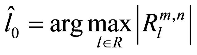
where E{.} denotes the expectation operator. The position of the node is estimated by maximizing the correlation coefficient , i.e.,
 (4)
(4)
Due to imperfect channel estimation at the receiver the ideal correlation cannot be attained. Hence, a correlation threshold Rth is used such that, . The values of
  crosses Rth are defined as
 , where k is the number of values of
  crosses Rth Then the values of
  are indexed with their corresponding location coordinates in descending order. Finally, the node location is calculated by taking a weighted average of the coordinates of the first three locations in the index, assuming these three locations are very close to the node location.
4. Proposed Hybrid Geo-Location Algorithm Combining TOA and FP Approaches
Our proposal for hybrid localization is a combination of the CIR-based FP positioning and iterative-TOA positioning methods. It is obvious that an iterative positioning algorithm needs an initial guess which will influence the iterative process. A good approximation of the initial value also reduces the calculation complexity as well as increases the positioning accuracies. In the proposed hybrid geo-location, the source location estimated in the FP method is considered as the accurate initial values for an iterative-TOA method. The Levenberg-Marquardt [16,17] based iterative algorithm (will be described in the later part of this chapter) is used to mitigate non line-of-sight (NLOS) error in the iterative process of the hybrid positioning.
Let N access points (AP)s and a target deployed in the 2-dimensional space. An access point is a node whose position is known as priori, while a target is a node whose location is to be determined.
Consider  and
and  be row vectors whose elements are the coordinates of the i-th anchor ai =
  with
with  and the target
 , respectively. The Euclidean distance between the i-th anchor and target, denoted by di, is given by
 , where
  is the Frobenius norm.
Let denote  as a measurement sample of di by TOA estimation and given by,
 (5)
(5)
where, ri represents a random variable with Gaussian distribution and models small variation of the error due to thermal noise. Equation (5) can be rewritten in vector form as,
 (6)
(6)
where,  and
and  . We assume that a bound for the norm of noise,
 (7)
(7)
is explicitly known and that the linear system of equations associated with the error-free right-hand side,
 (8)
(8)
where,  is the vector of unknowns and
  is the data matrix. When
  and the columns of
  are linearly independent, we can estimate the target
  by solving the following least squares problem
 (9)
(9)
where,  denotes the square of Euclidean norm of residual and the matrix A is assumed to have many singular values of different orders of magnitude close to the origin. In general, the ratio between the largest and smallest singular values is very large and therefore the solution of (9) is very sensitive to perturbations in the vector b. Minimization of problems with the matrices of this kind commonly referred as discrete ill-posed problems. In this case, the regularization technique of changing ill-posed problem to an approximate problem is preferred. The regularized least squares problem has the quadratic form
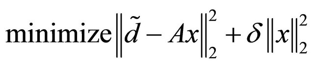 (10)
(10)
for some . Using
 ![]() is to prevent
is to prevent  from getting large when
 is ill-posed. So by choosing appropriate
![]() , we can control the size of the solution vector
, we can control the size of the solution vector ![]() as well as the size of the norm of residuals.
as well as the size of the norm of residuals.
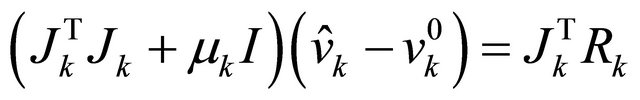
To find the approximate solution we apply the Levenberg-Marquardt (LM) [16,17] based iterative method which solves a 2-norm regularized linear least squares subproblem at each iteration. The search direction ![]() of LM method must satisfies
of LM method must satisfies
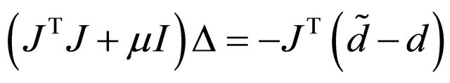 (11)
(11)
Therefore target location can be estimated by using the updating equation as,
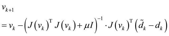 (12)
(12)
In Equation (12), J is the Jacobian and  is the damping factor; the value of
  affects both direction and step-size of iterations. When
  , LM approaches Steepest Decent (SD) method. When
  , LM method is reduced to Gauss-Newton (GN). The initial value of
  should be chosen according to the size of the elements in
 , such that [18]
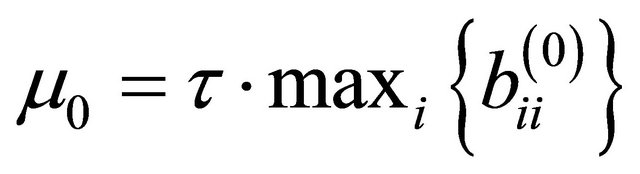 (13)
(13)
Here, τ is defined by the user (by a rule of thumb, but a small value should be chosen). Throughout iteration the size of  can be updated and is controlled by the cost function.
Computational Analysis of the Hybrid Positioning Method
The computational complexity of the hybrid positioning method can be described as the number of arithmetic operations required in LM algorithm to find the optimum solution for the ranging problem.
The computations of LM iterative algorithm is considered as expensive due to as it requires to estimate first and second order information like gradients, Jacobians and Hessians. For the convergence of the algorithm, the iteration K is highly dependent of on the initial point v0. However, as the ranging output of the fingerprinting method is provided as the initial point v0, the number of iteration is expected to be low for the convergence.
In this analysis we provide a detailed description of arithmetic operations in term of additions and subtractions (both as ADDs), multiplications (MULs), divisions (DIVs), and square roots (SQRTs).
The square root is an important arithmetic operation as it is required in ℓ2 norms to compute distances between target and anchors. Moreover, ℓ2 norms is required in computing error function  and the Jacobian estimate. It is notable that the complexity of computing the arithmetic operations counted in the simulation is not the same in terms of the processing resources (hardware and software) they take. We perform the analysis for a single iteration of the LM algorithm, and we assume that the convergence will occur after K iterations. Hence, the total cost for each operation is multiplied by K to get the overall cost for convergence. We assume there are M anchors which have broadcast their position to the target.
There are three major arithmetic operations in LM algorithm and these are ℓ2 or Euclidean norm, the error vector Rk and an estimate of Jk.
The ℓ2 norm or the Euclidian distance is computed as
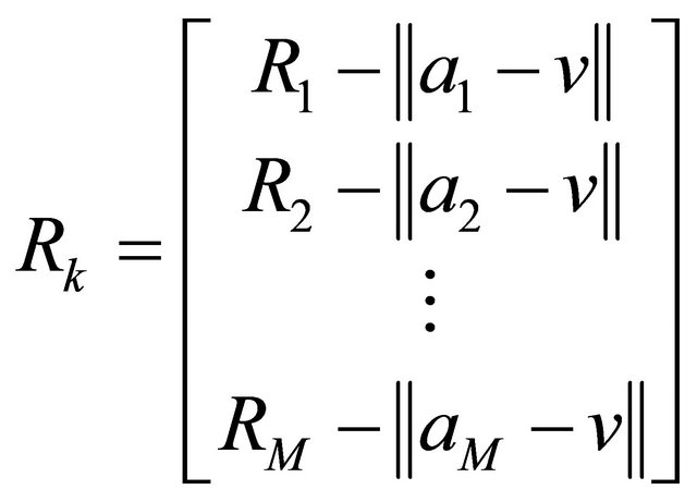
 Here the arithmetic operations are three ADDS, two MULs and one SQRT. The ℓ2 norm is also necessary to calculate Rk and to estimate Jacobian Jk as follows:
 (14)
(14)
 (15)
(15)
For Rk computations, it require M ADDs and M ℓ2- norms. Accounting for the norms, the error function requires 4 ADDs, 2 MULs, and 1 SQRT. So it needs 7 m floating point operations (flops) to compute Rk. Similarly in each iteration, the computations for the Levenberg-Marquardt (LM) has the updating part of m × n Jacobian matrix Jk and the equation
 (16)
(16)
The computational complexity of the Jacobian and other operations are shown as in the Table 1.
Hence, the total number of flops, including common terms to measure the complexity of the LM algorithm becomes,
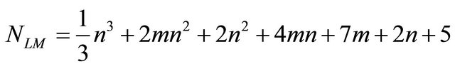 (17)
(17)
The above expression is the computational complexity of hybrid method in each iteration for a sample data.
5. Numerical Analysis by Simulations
The performances of FP geo-location method with various fingerprinting polygons (discussed in the previous Chapter) are evaluated in this chapter. Moreover, a comparison of the proposed hybrid method with TOA only, FP only and a conventional iterative method is shown in the later part of the chapter.
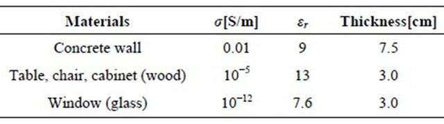
Tables 2 and 3 show the parameter values for evaluating model’s performances and the properties of materials we employed in the RT technique, respectively.
To get the accurate results in the ray launching type RT technique, many rays have to be launched and only a fraction of these reach the receiver. The accuracy of this technique also depends on the radius of the reception sphere. If it is too small, rays will pass by. If it is too large, paths might be duplicated. We set the radius of the reception sphere at 1.5 cm. Moreover, we consider the reflection of rays up to the third order, since the received
Table 1. Computational complexity.
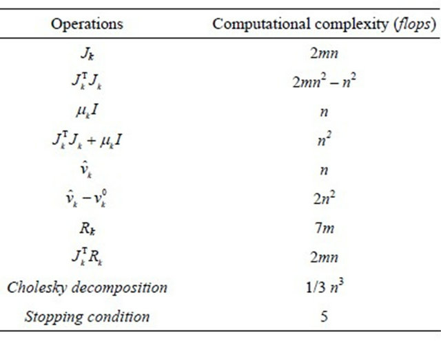
Table 2. Parameter values for evaluating model’s performance.

Table 3. Properties of the materials employed in RT technique.
signal strength beyond third order ray reflection becomes very low and is neglected. CIRs collected by the RT technique are convoluted with a UWB signal with bandwidth of 2 GHz. To consider a sufficient amount of multipath effects in the CIR pattern for NLOS incidences we allow a wider observation window, i.e., 65 ns, since the probability that the direct path is further apart from the strongest path is higher in the NLOS than in LOS. Therefore, it could accommodate maximum of 20 paths in the CIR patterns of NLOS cases.
As we consider an indoor office room of size 10 m × 8 m for our simulations, we think four APs are enough to cover radio mapping of this limited area and adequate for CIR-based FP geo-location. It is obvious that increasing the number of AP would increase the possibility of LOS incidences and thus improve the accuracy in TOA-based geo-location. However, increasing the number of APs will also increase the size of the fingerprinting database and thus increase the computational complexity of geolocation in the FP method.
5.1. Effect of Different Sizes of Polygon in FP Geo-Location
To evaluate the performance of the FP method for geolocation of the same test nodes which are used in an iterative TOA geo-location, we place the reference nodes (or tags) in such a manner to form polygon shapes (as mentioned in Section 2.2). We employ three different sizes of polygon, 20 cm, 30 cm, 40 cm, 50 cm, 60 cm, 70 cm and 80 cm and evaluate the positioning accuracy by varying signal’s sampling rate (i.e., 30 GHz, 50 GHz and 80 GHz) for each case.
Figure 4 shows the performance of FP method for three different NLOS rates (when, polygon size: 50 cm).
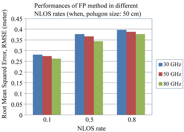
Figure 4. Performance of FP method in different NLOS rates (when, polygon size: 50 cm).
Here, the cases with received signal’s higher sampling rate provide slightly better positioning accuracies. Because, the higher sampling rate of the received signal reduces the time quantization error in the time delay estimation. Therefore, positioning accuracy increases with higher time resolutions. We also compare the geo-location performances of FP method for different NLOS rates. NLOS rate is defined as the ratio of the number of nodes experiencing NLOS and the total number of nodes considered for localization. For instance, a NLOS rate of 0.5 means the half of the total number of test nodes are experiencing NLOS.
Moreover, the positioning accuracies also degrade if we increase NLOS rates. In NLOS situations, unlike LOS conditions the position estimation mostly depends on the multipath components of the received signal. Therefore, the estimated position would be very far away from the real position of the test node in NLOS conditions. As the estimated position is shifted from its real position, it is more likely to match the CIR pattern of estimated location with that of a far location point rather than matching CIR pattern of the point near to its real position. The number of such instances increases if we increase the NLOS rates, hence positioning accuracy degrades. Figures 5-7 show the CDF of distance error in the FP method for LOS cases and as well as two different cases of NLOS respectively. With a NLOS rate of 0.2, the case with polygon size of 20 cm has 40% probability to achieve accuracy of less than 10 cm; whereas with a NLOS rate of 0.8, to achieve the same level of accuracy the case with polygon size of 20 cm has the probability of 25%. Similarly, for a NLOS rate of 0.2, the case with polygon size of 40 cm has 60% probability to achieve accuracy of less than 20 cm; whereas with a NLOS rate of 0.8, to achieve the same level of accuracy the case with polygon size of 40 cm has the probability of 20%. Therefore, if the NLOS rate is increased consid-

Figure 5. CDF of localization error for FP method for LOS cases.
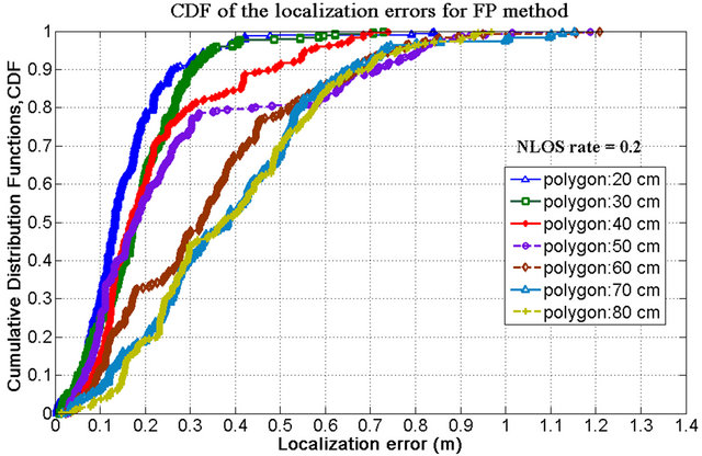
Figure 6. CDF of localization error for FP method for NLOS rate of 0.2.
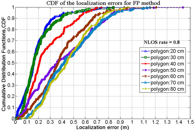
Figure 7. CDF of localization error for FP method for NLOS rate of 0.8.
ering the same polygon size, the probability to achieve less localization error would be decreased. The performance of FP method for cases with various polygon sizes in different NLOS rates are also summarized in Figure 8. Besides, Figure 9 shows that the cases with higher sampling rates have the better geo-location accuracies.
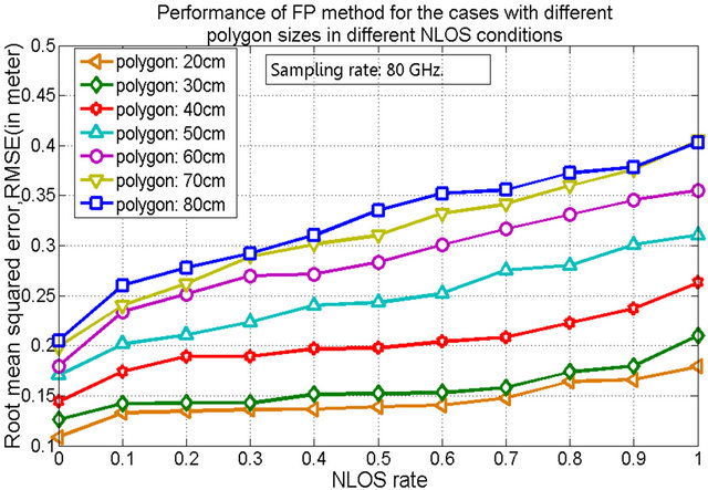
Figure 8. Performance of FP method for cases with various polygon sizes in different NLOS rates, when sampling rate: 80 GHz.
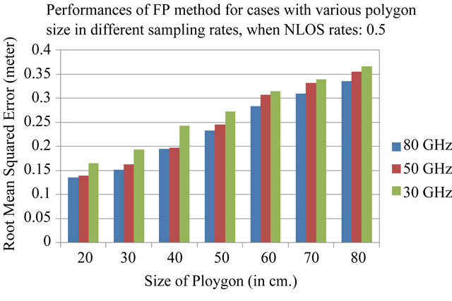
Figure 9. Performance of FP method for cases with various polygon sizes in different sampling rates, when NLOS rate: 0.5.
5.2. Performance of Hybrid Geo-Location Method with Different NLOS Rates
As mentioned earlier, we have used Levenberg Marquardt based iterative algorithm to minimize the cost function in order to estimate the node position. This optimization algorithm reduces the NLOS error in geolocation effectively. Therefore, as shown in Figure 10, the geo-location accuracy of proposed hybrid method increases for cases with various polygon sizes in different NLOS rates. The figure depicts that the smaller polygon size in FP geo-location provides better location accuracies in the hybrid method; whereas, higher the rates of NLOS, lower the geo-location accuracies due to increased number of NLOS nodes. Moreover, Figure 11 shows that the cases with higher sampling rates have the better geo-location accuracies. Because, the higher sampling rate of the received signal reduces the time quantization error in the time delay estimation. Hence, geolocation accuracy increases with higher time resolutions.
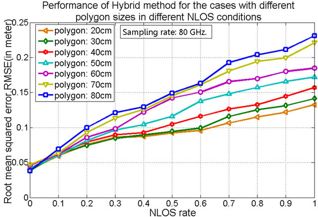
Figure 10. Geo-location accuracies in hybrid method for various cases with polygon sizes in different NLOS conditions, [sampling rate: 80 GHz].

Figure 11. Performance of hybrid method for cases with various polygon sizes in different sampling rates, when NLOS rate: 0.5.
5.3. Comparison of Proposed Hybrid Method with Other Geo-Location Methods
In the proposed hybrid method, there is possibility to get mutual benefits from the TOA only and FP only methods. If any case in FP method does not have better geo-location accuracy than the TOA only method, so the hybrid method can choose its initial value from the geo-location result of TOA only method for iterations.
In comparison with other geo-location methods, the proposed hybrid method has better geo-location accuracies, as shown in Figure 12, by mitigating NLOS error than TOA only, FP only and a conventional iterative method under different NLOS rates in the dense multipath radio propagation where the office room contents huge furniture. In a conventional iterative TOA method, we also applied the Levenberg-Marquardt iteration algorithm; however, initial values are random guesses unlike considering the geo-location results of the FP method. In this figure, FP method has much better geo-location accuracies than TOA only and conventional iterative
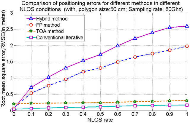
Figure 12. Comparison on geo-location accuracies for TOA only, FP only, conventional iterative TOA and hybrid methods in NLOS conditions.
method for different NLOS rates. Because, FP method has gathered the pre-knowledge of NLOS propagations while generating CIR pattern database for various reference locations in the training phase. However, TOA only method does have any pre-knowledge of NLOS propagations in ranging procedures. Similarly, the proposed method also renders better geo-location accuracies than the Gauss-Newton based iterative-TOA geo-location method, reported in [19].
5.4. Tradeoff between Geo-Location Accuracies and Computational Complexities in Proposed Hybrid Method
The results demonstrated in Figures 13-15 are the tradeoff between computational complexity in floating point operations (flops) and geo-location accuracies in RMSE for the proposed hybrid method in LOS cases and the cases with NLOS rates of 0.2 and 0.8 respectively. Here, the computational complexity measures the total number of arithmetic operations (in flops) required for convergence in the iteration process for 300 input data samples. In these figures, the larger number of flops in the horizontal axis resembles the higher amount of arithmetic operations required for computations.
For LOS cases, in Figure 13, if we choose our desire accuracy between 4.0 cm to 4.2 cm, the cases of polygon size: 30 cm and 40 cm with different sampling rates have the geo-location accuracy within this range. Besides, the case with polygon size: 30 cm with Sampling rate: 30 GHz has the lesser computational complexity, hence be chosen as an optimum case for hybrid geo-location with LOS cases.
For NLOS rate of 0.2, as shown in Figure 14, the four cases with polygon size: 20 cm and polygon size: 30 cm have the geo-location accuracy between 7 cm to 8 cm. Among them, the case of polygon size: 30 cm with Sampling rate: 50 GHz has the lesser computational complexity. Hence, the case of polygon size: 30 cm with Sampling rate: 50 GHz can be chosen as an optimum case for hybrid geo-location when NLOS rate is 0.2.
In the similar way, in Figure 15, if we choose our desire accuracy between 15 cm to 20 cm in NLOS rate of 0.8, the cases of polygon size: 20 cm with Sampling rate: 30 GHz and of polygon size: 20 cm with Sampling rate: 50 GHz are the two cases of those have the geo-location accuracy within this range. Besides, the case with polygon size: 20 cm with Sampling rate: 30 GHz has the lesser computational complexity, hence be chosen as an optimum case for hybrid geo-location when NLOS rate is 0.8.
6. Conclusion
We proposed a hybrid approach for geo-location of mobile or wireless sensor nodes using UWB signaling
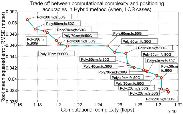
Figure 13. Tradeoff between computational complexities and geo-location accuracies in Hybrid method, for LOS cases (where, Poly: Polygon; fs: Sampling rate).
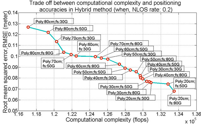
Figure 14. Tradeoff between computational complexities and geo-location accuracies in Hybrid method, when NLOS rate: 0.2 (where, Poly: Polygon; fs: Sampling rate).
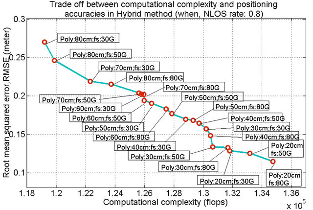
Figure 15. Tradeoff between computational complexities and geo-location accuracies in Hybrid method, when NLOS rate: 0.8 (where, Poly: Polygon; fs: Sampling rate).
which combines the CIR-based FP geo-location with polygonal arrangement of training nodes and iterativeTOA real time geo-location methods. The proposed hybrid method follows a Levenberg-Marquardt based iterative algorithm, which effectively reduces NLOS errors. Our simulation results show that the proposed hybrid method yields better performances and is more robust in NLOS error mitigation than TOA only, FP only and a conventional iterative method in the dense multipath indoor radio propagation environment. The optimum size of polygon is predicted while evaluating the trade-off between accuracies in the proposed hybrid method and the complexities in geo-location calculations. However, in the most realistic cases of indoor environment, furniture could be moved and radio propagation environment could be changed in times. Therefore, it requires more investigation on how fingerprints database could be updated to deal with the dynamic nature of the indoor propagation environment to provide more accurate geolocation.
REFERENCES
- M. H. Kabir and R. Kohno, “A Hybrid TOA Fingerprinting Based Localization of Mobile Nodes Using UWB Signaling for Non Line-of-Sight Conditions,” Sensors, Vol. 12, No. 8, 2012, pp. 11187-11204. doi:10.3390/s120811187
- N. B. Priyantha, A. Chakraborty and H. Balakrishnan, “The Cricket Location-Support System,” Proceedings of MobiCom 2000, Boston, 6-10 August 2000, pp. 32-43.
- P. Bahl and V. N. Padmanabhan, “RADAR: An In-Building RF-Based User Location and Tracking System,” Proceeding of the IEEE INFOCOM 2000, Tel Aviv, 26-30 March 2000, pp. 775-784.
- S. G. Razul, C.-H. Lim and C.-M. S. See, “Bayesian Method for NLOS Mitigation in Single Moving Sensor Geo-Location,” Signal Processing, Vol. 91, No. 7, 2011, pp. 1613-1621. doi:10.1016/j.sigpro.2011.01.005
- W. Ke and L. Wu, “Mobile Location with NLOS Identification and Mitigation Based on Modified Kalman Filtering,” Sensors, Vol. 11, No. 2, 2011, pp. 1641-1656. doi:10.3390/s110201641
- C.-D. Wann, “Kalman Filtering for NLOS Mitigation and Target Tracking in Indoor Wireless Environment,” In: V. Kordic, Ed., Kalman Filter, IN-TECH Education and Publishing, Vienna, 2010.
- M. Boccadoro, G. D. Angelis and P. Valigi, “TDOA Positioning in NLOS Scenarios by Particle Filtering,” Wireless Networks, Vol. 18, No. 5, 2012, pp. 579-589. doi:10.1007/s11276-012-0420-9
- S. Dayekh, S. Affes, N. Kandil and C. Nerguizian, “Cooperative Geo-Location in Underground Mines: A Novel Fingerprint Positioning Technique Exploiting SpatioTemporal Diversity,” Proceedings of the IEEE International Symposium on Personal, Indoor and Mobile Radio Communications (PIMRC) 2011, Toronto, 11-14 September 2011, pp. 1319-1324.
- G. Ding, Z. Tan, L. Zhang, Z. Zhang and J. Zhang, “Hybrid TOA/AOA Cooperative Localization in Non-Lineof-Sight Environments,” Proceedings of the IEEE Vehicular Technology Conference (IEEE VTC 2012 Spring), Yokohama, 6-9 May 2012, pp. 1-5.
- C. Mensing and S. Plass, “Positioning Algorithms for Cellular Networks Using TDOA,” Proceddings of the IEEE International Conference on Acoustics, Speech and Signal Processing, Toulouse, 14-19 May 2006, pp. 1-4.
- D. Akbarov, H. Choi, Y. Park, G. Han and J. Moon, “Hybrid Pattern Matching/TDOA Positioning Method for CDMA Networks,” Proceeding of the 4th Workshop on Positioning, Navigation and Communication (WPNC), Hannover, 22 March 2007, pp. 199-203. doi:10.1109/WPNC.2007.353634
- J. Diskin and C. Brennan, “Accelerated Ray-Tracing for Indoor Ultra-Wideband Propagation Modeling,” Proceedings of the IEEE Vehicular Technology Conference (VTC), Dublin, 22-25 April 2007, pp. 418-422.
- K. R. Schaubach, N. J. Davis and T. S. Rappaport, “A Ray Tracing Method for Predicting Path Loss and Delay Spread in Microcellular Environments,” Proceedings of the IEEE Vehicular Technology Conference (VTC), Denver, 10-13 May 1992, pp. 932-935.
- G. L. Turin, F. D. Clapp, T. L. Johnston, S. B. Fine and D. Lavry, “A Statistical Model of Urban Multipath Propagation,” IEEE Transactions on Vehicular Technology, Vol. 21, No. 1, 1972, pp. 1-9. doi:10.1109/T-VT.1972.23492
- W. Q. Malik and B. Allen, “Wireless Sensor Positioning with Ultra Wideband Fingerprinting,” The 1st European Conference on Antennas and Propagation (EuCAP 2006), Nice, 6-10 November 2006, pp. 1-5.
- D. W. Marquardt, “An Algorithm for Least-Squares Estimation of Nonlinear Parameters,” Journal of the Society for Industrial and Applied Mathematics, Vol. 11, No. 2, 1963, pp.431-441. doi:10.1137/0111030
- A. Ranganathan, “The Levenberg-Marquardt Algorithm,” Honda Research Institute USA, 8 June 2004, Retrieved 12 August 2012. http://www.ananth.in/Notes_files/lmtut.pdf
- K. Madsen, H. B. Nielsen and O. Tingleff, “Methods for Non-Linear Least Squares Problems,” 2nd Edition, Lecture Notes, Informatics and Mathematical Modelling, Technical University of Denmark, Lyngby, 2004, p. 25.
- M. H. Kabir and R. Kohno, “A Hybrid Positioning Approach by UWB Radio Communication Systems for Non Line-Of-Sight Conditions,” Proceedings of the IEEE Global Communications Conference (GLOBECOM) 2011, Houston, 5-9 December 2011, pp. 1-5.
NOTES
*Corresponding author.