Journal of Software Engineering and Applications
Vol.08 No.08(2015), Article ID:58871,11 pages
10.4236/jsea.2015.88037
An Integration of UML Sequence Diagram with Formal Specification Methods― A Formal Solution Based on Z
Nasir Mehmood Minhas, Asad Masood Qazi, Sidra Shahzadi, Shumaila Ghafoor
University Institute of Information Technology, PMAS-University Institute of Information Technology, Rawalpindi, Pakistan
Email: nasirminhas@uaar.edu.pk, asad.masood@dpskw.com, sidra.shahzadi363@gmail.com, shumailaghafoor90@gmail.com
Copyright © 2015 by authors and Scientific Research Publishing Inc.
This work is licensed under the Creative Commons Attribution International License (CC BY).
http://creativecommons.org/licenses/by/4.0/


Received 6 July 2015; accepted 16 August 2015; published 19 August 2015
ABSTRACT
UML Diagrams are considered as a main component in requirement engineering process and these become an industry standard in many organizations. UML diagrams are useful to show an interaction, behavior and structure of the system. Similarly, in requirement engineering, formal specification methods are also being used in crucial systems where precise information is required. It is necessary to integrate System Models with such formal methods to overcome the requirements errors i.e. contradiction, ambiguities, vagueness, incompleteness and mixed values of abstraction. Our objective is to integrate the Formal Specification Language (Z) with UML Sequence diagram, as sequence diagram is an interaction diagram which shows the interaction and proper sequence of components (Methods, procedures etc.) of the system. In this paper, we focus on components of UML Sequence diagram and then implement these components in formal specification language Z. And the results of this research papers are complete integrated components of Sequence diagram with Z schemas, which are verified by using tools and model based testing technique of Formal Specifications. Results can be more improved by integrating remaining components of Sequence and other UML diagrams into Formal Specification Language.
Keywords:
Formal Specifications, Software Requirement Specifications, Formal Notations

1. Introduction
Formal Methods are based on mathematical techniques, which can be used in any phase of Project life cycle, especially in an initial stage. When requirements are gathered from clients, project team has to know about the system. There are many techniques of formal methods, like Model based Languages, Process Oriented and Algebraic Specifications.
In Software Engineering, formal specifications and UML Diagrams are very useful to understand the requirements and specifications of the system. Formal specifications and UML are used since many years in Software Engineering, and UML diagrams are considered as a standard tool in many organizations. There is a complete method in Software Engineering named as “Clean Room Software Engineering” [1] basically based on formal specifications. The idea behind the Clean Room SE is “Do it Right, at first Time”. It is composed of gathering requirements, and then transforms them into statistical methods, so there will no need of unit testing.
UML diagrams are important to understand the complexity of system. UML describes the behavior and structure of a program. Also, they describe the interaction of components with the system. These include Use Case, Class, Activity and many other diagrams. UML diagrams are easy to understand by the users, developers and domain experts whereas the formal methods are difficult to understand by the users, domain experts and developers as well.
Before go forward, we also need to know that where the specification part lies actually in the Requirement engineering process. A brief detail of requirement engineering process is given below:
Software requirement engineering involves requirements elicitation, requirements specification, requirements validation and requirements management [2] [3] . Requirements elicitation involves the ways of gathering the requirements which include many traditional, cognitive, model based techniques etc.
Whereas, the requirements Specification (where analysis and negotiation of requirements are performed), requirements of users are specify to make them understandable and meaningful for developers. Specifications can be formal as well as non-formal [4] . Formal techniques include the set of tools and techniques based on mathematical models whereas informal techniques are based on modeling the requirements in diagrams or making architecture of system. There are many techniques in both types of specification. Like in formal techniques of specifications, we have different formal specification languages like Z, VDM etc. and in in-formal or non-formal techniques, we have UML diagrams which include use-cases, sequence diagrams, collaboration and interaction diagrams etc.
In Requirements validation, the completeness of the requirements being checked which means either gathered requirements are correct, complete or not. The main objective to analyze the validation and verification of RE process to identify and resolve the problems and highly risk factors of software in early stages to make strengthen the development cycle [5] . Finally, in Requirements management phase, issues and conflicts of users are resolved. According to Andriole [6] , the requirement management is a political game. It is basically applied in such cases where we have to control the expectations of stakeholders from software, and put the requirements rather than in well-meaning by customers but meaning full by developers, so they can examine that, they actually full fill the user’s requirements.
Authors of [7] include the Requirement change management under the Requirement Engineering process. RCM is a term which is used as the history or previous development of the similar software product (s). On the basis of historical development, we investigate the need of RCM or not.
Unique Features of Sequence Diagrams
There are some unique features of Sequence diagrams and also reasons for choosing sequence diagrams for this research purpose, which are:
・ Sequence Diagrams are used to show the priorities of steps/modules of system, Lower step denotes to the later.
・ Reverse Engineering of UML sequence diagrams are used to support reverse engineering in software development process [8] .
・ It shows a dynamic behavior of system and considered as good system architecture design approach [9] .
・ Sequence diagrams include the Life line of the objects, and it can be easily integrated because of Time dimension [10] .
・ We can use messages to make it understandable by all stakeholders.
・ We can also use loops, alternatives, break, parallelism between complex components of system and many more [10] .
Our Idea is to work on integration of UML Sequence Diagram’s attributes with formal specification methods like Z notations to bridge a gap between both (formal and informal) methods. So, once we make a sketch of any system in to Sequence diagram to show its sequence of steps, requirement priorities, time bar information and others, then we will transform these attributes into Z schemas. So it will be an easy for developers, to develop system if they had requirements in proper mathematical forms. Also, there was a research gap of properly integration of Sequence diagrams with formal specifications.
2. Related Work
The Integration of formal and in formal methods of specification is not a new area, it is being used by many software industries as well as there is a complete area of research in Software engineering to tackle the limitations of both techniques and transform them into an intermediately solution. Many studies are there which are helpful to integrate the Z notations with Scrum, requirement elicitation and many other areas.
In [11] , authors represents a conceptual solution to formalize the Class Diagrams, in which they formalize the class diagrams through steps including representing classes in Z, representing associations in Z representing aggregation in Z and then represent generalization of classes in Z.
Similarly, in [12] researchers represent a conceptual solution to integrate XP methodology with Z. They work on user stories phase, where user stories will be verified through Formal Verification techniques. It can also be observed from [13] in which integration of the Z notations into Use case Diagram, because use case diagrams are very common in software development companies, as these are easy to understand by all stakeholders, so they apply Z on them, to bridge a gap between formal and informal techniques. It has been observed from [14] , which is study on an Integration of formal methods into agile methodology that formal methods can lead towards a better software development solution. In [15] , they apply formalization in the requirement specification phase of Requirement Engineering Process. They describe an analyzing phase, in which they will focus on such a specification which is being analyzed early.
Concept of making Z schemas of UML class and sequence diagrams on the basis of some semantic rules can also be found in the [16] [17] . Firstly, a Video on Demand case study is been taken in this study, then authors draw its class structure diagram to shows the hierarchy of the classes, and then Z schemas are defined. Secondly, sequence diagram is generated on same case study, furthermore its objects are defined in a complete way using Z schemas.
Tony Spiteri [18] takes a case study, transform it into UML diagrams, and then implement the specifications into formal method languages, then apply optimization methods to minimize the computing resources; total time and total cost. in [19] -[21] z notations based schemas are applied in some real life examples and case studies, furthermore, the authors also uses z/eves tool for formal model check as well as z schemas verification. In [11] , very important concept can be found related to this study, in which sequence diagram is analyzed through the states of the system and their relationship according to the message using state transitions graphs.
3. Expectations from System Specifications
In any system development, we gather the requirements from users and then we try to understand “What” should be done, but formal specification methods also specify “Why” should be done. For moving from analysis to implementation we have to identify these (and many else) variables from [22] -[24] .
3.1. Domain Knowledge
Understanding about the system as well as its context, and it should be known by all stakeholders. For example for Library management system, there should be complete understanding about the library environment and ordinary procedures followed by Library. Similarly for Airline reservation system, there should be a complete knowledge about its possible components like scheduling, ticketing boarding etc.
3.2. User’s Requirements
These are the requirements which are not the requirements of system. Actually, these requirements are defined by the client or user to make it efficient or easy to use, like cost, ease of use etc. are the examples of user’s requirements.
3.3. System Requirements
These requirements are purely related to the system, which must be included in the system. For example a flight reservation system must include the flight place with time and date.
3.4. System Specification
To specify the gathered requirements, software engineers’ uses many ways to transform the story based requirements into a meaningful form for developers. These specifications are not basically dependent to any design, these can be in form of abstract prototypes, formulas procedures or else. In this part, specifications are sent to the developers to implement them, and testers to test them and to the users to verify them.
3.5. Design Structure
In design structure, we have to focus on “How” part. For example how the functionality is allocated to the system component, how the system’s components will communicate each other etc.
3.6. Problem Refinement
Formal notation methods like VDM and Z helps the software engineers to refine the problem. In user’s stories which problem look more complex, and involve complex mathematical structure, we refine it by using formal methods, so by specify the relationship between components problem becomes in more refined shape.
4. Proposed Solution
Formal specifications use mathematical notation and provide state requirements and mechanism for the verification of system correctness. Z specification provides a mathematical technique to model relation via predicate calculus that has states and relational functions [9] . Our Research will basically focus on implementation of UML Sequence diagram into Z. So, to implement our problem we proposed some sequence of steps which is given in Figure 1.
5. Formalization of Flight Reservation System
5.1. UML Sequence Diagram as an Input
A flight reservation system may contain the records of flights, which includes the place, date and time of flight, airline name, number of seating capacity or number of tickets, list of users etc. Now on the basis of this given data, following operations can be performed like Creation of Reservation, Cancel the reservation, Sign In/Sign Up etc. UML sequence diagram for Flight reservation system can be seen in Figure 2.
5.2. States-Transition Diagram
To set some grammar rules we have to identify the state transition graph or diagram. So, on the basis of these grammar rules we can formalize our sequence diagram’s components. The State UML diagram is given in Figure 3.
5.3. Define Grammar Rules
In transformation procedure from state to grammar development is given in Table 1. In transformation

Figure 1. Proposed solution steps to integrate UML sequence architecture with formal specification methods.
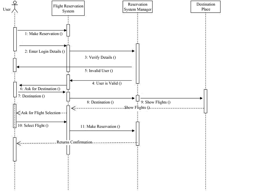
Figure 2. UML sequence architecture of flight reservation system.

Figure 3. State Transition graph/diagram on the basis of UML sequence diagram.

Table 1. States-transition table with their termination conditions.
there are certain states regarding each object and messages execute from one state another state, a production rule is created, for the execution of message if there is no condition null condition is supposed. We can elaborate this concept with the help of example for this consider row 1 where m1 (message 1: make reservation) execute from state S0 to S1 here no condition is imposed for execution so, there is null condition. We can determine final states from given table where S2, S10 are final states and rest of all are failure of operation.
Using Table 1: After constructing rules regarding each message now, here for the termination of the process the null production are added, represented by derivation tree for parsing of a scenario.
Rule (r1): S0 ⇒ m1S1, null|m2S2, null,
Rule (r2): S1⇒∈,
Rule (r3): S2 ⇒ m3S3, c1,
Rule (r4): S3 ⇒ m4S4, null|m5S5, null,
Rule (r5): S4⇒∈,
Rule (r6): S5 ⇒ m6S6, null,
Rule (r7): S6 ⇒ m7S7, null,
Rule (r8): S7 ⇒ m8S8, null,
Rule (r9): S8 ⇒ m9S9, null,
Rule (r10): S9 ⇒ m10S10, null|m10S10, null,
Rule (r11): S10 ⇒ m11S11, null|m12S11, c2.
To check validation we can derive by above diagram which we have constructed in grammar rules, here is only the validation for S0, we can check for all states like this way:
According to r1 S0 ⇒ m2S2, now if we apply r3 we get m3S
S0 ⇒m2S2
(By applying r3 on S2 we get m3S3)
⇒m2m3S3
(By applying r4 on S3 we get m5S5)
⇒m2m3m5S5
(By applying r6 on S5 we get m6S6)
⇒m2m3m5m6S6
(By applying r7 on S6 we get m7S7)
⇒m2m3m5m6m7S7
(By applying r8 on S7 we get m8S8)
⇒m2m3m5m6m7m8S8
(By applying r9 on S8 we get m9S9)
⇒m2m3m5m6m7m8m9S9
(By applying r10 on S9 we get m10S10)
⇒m2m3m5m6m7m8m9m10S10
(By applying r11 on S10 we get m11S11)
⇒m2m3m5m6m7m8m9m11S11
5.4. State-Transition Table
Rules for Constructing Z Schemas:
Rule 1:
S0 ˄ S1 ?states, if current (state) = i then new (state) = i+1, condition c = null for the execution, message = m1 will move from S0 to S1. Creation and termination time of object (passenger) is between start and end time of S0, S1, and same in the case of message m2.
Rule 2:
S2 ˄ S3 ?states, if current (state) = i then new (state) = i+1, condition c = c1 for the execution, message = m3 will move from S2 toS3 regarding objects flight reservation system and reservation system manager. Termination and creation time of these objects (o1, o2) must not be greater than the time require for the start and end of states S2, S3.
Rule 3:
S3 ˄ S4 ?states, if current (state) = i then new (state) = i+1, condition c = null for the execution, message = m4 will move from S3 toS4 regarding objects flight reservation system and reservation system manager. Termination and creation time of these objects (o2 to o1) must not be greater than the time require for the start and end of states S3, S4.
Rule 4:
S8 ˄ S9 ?states, message m9 execute by fulfilling condition c9. Termination and creation time of these objects (o3 to o4) must not be greater than the time require for the start and end of states.
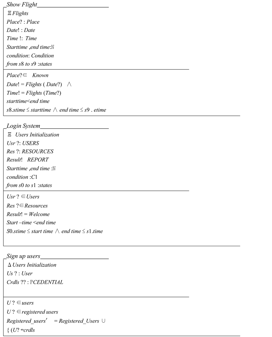
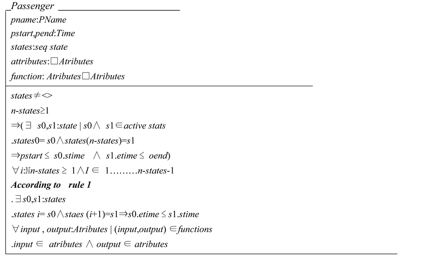
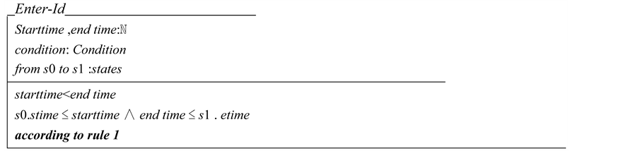
5.5. Z Schemas Generation
In schema generation, we are using Z as formal specification language. The schema’s mentioned below are the schemas of the sequence diagram of flight reservation system, which are based on the set of grammar rules, which we define earlier. Schemas are defined at the Appendix.
6. Testing and Verification
We have taken a small case study to work on this particular area, so we can test and validate our schemas and model efficiently. Our Z schemas are written in Z word tool, in which there is an option for type checking Z schemas using tool fuzz. Our grammar rules are semantic based solutions, which can be clearly seen in our state transition diagram. For model check we have used the same tool. Our resultant schemas are error free, but the results can also be improved through using other tools and techniques like Z/eves, CZT and many others.
The procedure of our testing was based on Z word tool which uses fuzz tool for type checking. The tool can be downloaded from Internet, and after installing we can use following procedure as described in Figure 4 for Type Check.
By executing schemas, we achieve correctness of our schemas as described in Figure 5.
7. Limitations and Future Work
The case study, which we take as a reference is a simple study, and does not cover all the features of Z, also this integration make the system more complex for understandable to normal stake holders like Users. Although a sequence diagram is decomposed into parts, which means modules, sub modules, their relations etc. are extracted but overall cost of system in terms of time and money can be increased, that is why, formal specifications were not cordial welcomed by software industry. But now in this study and related previous (referenced) studies

Figure 4. Type check specification.

Figure 5. On Execution of Schemas the correctness is shown.
a gap between formal and informal methods of requirement engineering and specifications are bridged.
Furthermore, there are many other informal techniques which are needed to be formalized like many development models, requirement elicitation techniques which are typically based on user stories etc. Also we can improve the results by using other formal and mathematical techniques and algorithms to optimize the results and decrease the overall cost of system.
8. Conclusions
In this paper, we have focused on the integration of UML sequence diagram into using Z specification language. For this we take a system “the Flight Reservation System” by following all procedure as described in our methodology, we formalize our system into Z specification as well as we try to accommodate maximum features of UML diagrams into our proposed solution by applying some grammar rules, which are used in our semantic based solution.
Our formal specification method is based on the UML diagrams include sequence and state diagrams, and our objective is to integrate them using Z schemas notations. But it was not an easy task to include all the features and applications in one paper or one solution. But overall Z schemas are analyzed and tested using fuzz as a type checking.
Cite this paper
Nasir MehmoodMinhas,Asad MasoodQazi,SidraShahzadi,ShumailaGhafoor, (2015) An Integration of UML Sequence Diagram with Formal Specification Methods—A Formal Solution Based on Z. Journal of Software Engineering and Applications,08,372-383. doi: http://dx.doi.org/10.4236/jsea.2015.88037
References
- 1. Selby, R.W., Basili, V.R. and Baker, F.T. (2006) Cleanroom Software Development: An Empirical Evaluation. IEEE Transactions on Software Engineering, SE-13, 1027-1037.
- 2. Chikh, A. (2011) A Knowledge Management Framework in Software Requirements Engineering Based on SECI Model. Journal of Software Engineering and Applications, 4, 718-728.
http://www.SciRP.org/journal/jsea
http://dx.doi.org/10.4236/jsea.2011.412084 - 3. Flores, F., Mora, M., álvarez, F., et al. (2010) Towards a Systematic Service Oriented Requirement Engineering Process (S-SoRE). Proceedings of the International Conference, CENTERIS 2010, Viana do Castelo, 20-22 October 2010, 111-120. http://dx.doi.org/10.1007/978-3-642-16402-6_12
- 4. Batra, M., Malik, A. and Dave, M. (2013) Formal Methods: Benefits, Challenges and Future Direction. Journal of Global Research in Computer Science, 4.
- 5. Boehm, B.W. (1984) Verifying and Validating Software Requirements and Design Specifications. IEEE Software Journal, 1, 75-88.
- 6. Andriole, S. and Safeguard Sci. Inc. (1998) The Politics of Requirements Management. IEEE Software Journal, 15, 82-84. http://dx.doi.org/10.1109/52.730850
- 7. Flores, F., Mora, M., álvarez, F., O’Connor, R. and Macias, J. (2008) Handbook of Research on Modern Systems Analysis and Design Technologies and Applications. In: Global, I.G.I., Ed., Chapter VI: Requirements Engineering: A Review of Processes and Techniques, Minnesota State University; Mankato, 96-111.
- 8. Rountev, A. and Connell, B.H. (2005) Object Naming Analysis for Reverse-Engineered Sequence Diagrams. Proceedings of the International Conference on Software Engineering, St. Louis, 15-21 May 2005, 254-263.
- 9. Zafar, N.A. and Alhumaidan, F. (2013) Scenarios Verification in Sequence Diagram. The Journal of American Science, 9, 287-293. http://www.jofamericanscience.org
- 10. UML Basics: The Sequence Diagram. http://www.ibm.com/developerworks/rational/library/3101.html
- 11. Shroff, M. and France, R.B. (1997) Towards a Formalization of UML Class Structures in Z. The 21st Annual International Computer Software and Applications Conference, 1997 (COMPSAC’ 97), Washington DC, 11-15 August 1997, 646-651. http://dx.doi.org/10.1109/cmpsac.1997.625087
- 12. Sgafiq, S. and Minhas, N.M. (2014) Integrating Formal Methods in XP—A Conceptual Solution. Journal of Software Engineering and Applications, 7, 299-310. http://dx.doi.org/10.4236/jsea.2014.74029
- 13. Sengupta, S. and Bhattacharya, S. (2006) Formalization of UML Use Case Diagram—A Z Notation Based Approach.
- 14. Black, S., Boca, P.P., Bowen, J.P., Gorman, J. and Hinchey, M. (2009) Formal versus Agile: Survival of the Fittest? IEEE Computer, 42, 37-45. http://dx.doi.org/10.1109/MC.2009.284
- 15. Fernández-y-Fernández, C.A. and José, M.J. (2012) Towards an Integration of Formal Specification in the áncora Methodology.
- 16. Spivey, J.M. (1998) The Z Notation: A Reference Manual. Prentice Hall International, Oxford.
- 17. El Miloudi, K., El Armani, Y. and Attouhami, A. (2013) Using Z Formal Specification for Ensuring Consistency in Multi View Modeling. Journal of Theoretical and Applied Information Technology, 57, 407-411.
- 18. Staines, T.S. (2007) Supporting UML Sequence Diagrams with a Processor Net Approach. Journal of Software, 2, 64-73. http://dx.doi.org/10.4304/jsw.2.2.64-73
- 19. Alhumaidan, F. and Zafar, N.A. (2013) Automated Semantics Treatment of Sequence Diagram Defining Grammar Rules. http://worldcomp-proceedings.com/proc/p2013/FCS7057.pdf
- 20. Zafar, N.A. (2006) Modeling and Formal Specification of Automated Train Control System Using Z Notation. IEEE Multi-Topic Conference (INMIC’06), Islamabad, 23-24 December 2006, 438-443.
http://dx.doi.org/10.1109/inmic.2006.358207 - 21. Zafar, N.A., Khan, S.A. and Araki, K. (2012) Towards the Safety Properties of Moving Block Railway Interlocking System. International Journal of Innovative Computing, Information & Control, 8, 5677-5690.
- 22. Heitmeyer, C.L., Jeffords, R.D. and Labaw, B.G. (1996) Automated Consistency Checking of Requirements Specifications. ACM Transactions on Software Engineering and Methodology, 5, 231-261. http://dx.doi.org/10.1145/234426.234431
- 23. Hall, A. (1996) Using Formal Methods to Develop an ATC Information System. IEEE Software, 13, 66-76. http://dx.doi.org/10.1109/52.506463
- 24. Bano, M. and Zwoghi, D. (2013) User’s Involvement in Requirement Engineering and System Success. IEEE 3rd International Workshop on Empirical Requirement Engineering, Rio de Janeiro, 15 July 2013, 24-31.
Appendix
Schemas for object in sequence diagram
Schemas for Messages in Sequence Diagram
Condition: = NULL |TRUE| FALSE
Schemas for Sequence Diagram
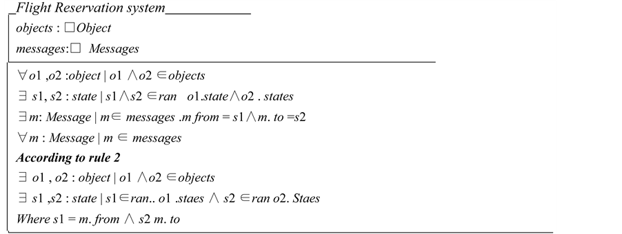
Operations in Reservation System