Positioning
Vol.2 No.2(2011), Article ID:5052,6 pages DOI:10.4236/pos.2011.22008
Template Match Object Detection for Inertial Navigation Systems
![]()
Beijing University of Aeronautics & Astronautics; Faculty of Engineering, Alexandria University
Email: weiduo.hu@gmail.com, alaaahafez@yahoo.com
Received January 2nd, 2011; revised May 13th, 2011; accepted May 20th, 2011.
Keywords: Template Match, Hit / Miss Transform, INS
ABSTRACT
This paper devoted to propose template match object detection for inertial navigation systems (INS). The proposed method is an image processing technique to improve the precision of the INS for detecting and tracking the ground objects from flying vehicles. Template matching is one of the methods used for ground object detection and tracking. Robust and reliable object detection is a critical step of object recognition. This paper presents a proposed mathematical morphological template matching method for detection and tracking of ground objects. Our focus is on flying systems equipped with camera to capture photos for the ground and recognize it. The proposed method is independent on the altitude or the orientation of the object. The algorithm is simulated using Matlab program and the numerical experiments are shown which verify the object detection for a wide range altitude and orientation. The results show superiority of this method for identifying and recognizing the ground objects.
1. Introduction
An INS is a navigation system which depends entirely on inertial measurements for navigation. An INS consists of accelerometers which measure the translator acceleration and gyroscopes which measure the angular rotation of the system. This sensor array is called an Inertial Measurement Unit (IMU). This system can be equipped with camera to fine tuning and improve the inertial navigation near the target of interest. This needs an image processing technique to identify and recognize the ground objects. Template matching techniques are methods commonly found in target-detection applications. These techniques allow users to customize their detection algorithms to specific targets of interest. The basis of template matching is the comparison of a representative pattern (template) of the target of interest with an image, with the purpose of detecting occurrences of the reference pattern in the image. Mathematical morphology is a branch of nonlinear signal and image processing that provides powerful tools for various image and signal processing applications. The Hit-or-Miss Transform (HMT) is a template matching method that exists within the mathematical morphology framework. The HMT has several benefits compared to other template-matching techniques, including the fact that it is based on rankorder operations which are generally faster than linear correlation techniques and that it is insensitive to DC variations of the template and the image. Several researches introduced the template matching in recognizing and identifying objects [1-3]. Therefore, a large amount of works are limited to detecting and matching objects in synthesized shape databases [4-5] or in special image domains. Previous works [6-10] on template-based object detection extract low-level image features such as edges, corners, regions and interest points, and then locate the target boundary by grouping the features and matching them to those on the template. In these works, computational complexity usually is very high, and object occlusion poses a great challenge to the detection algorithms. This paper introduce a simple template match object recognition technique able to detect and recognize the ground objects in the stage of fine tuning the INS for flying vehicles.
2. Theoritical Description
Template matching is conceptually a simple process. We need to match a template to an image where the template is a sub-image that contains the shape we are trying to find. Accordingly, we centre the template on an image point and count up how many points in the template matched those in the image. The procedure is repeated for the entire image, and the point that led to best match, the maximum count, is defined to be the point where the shape (given by the template) lie within the image. If standard deviation of the template image compared to the source image is small enough, template matching may be used. Templates are most often used to identify printed characters, numbers, and other small, simple objects. Template matching is performed on either bi-level image (black and white) or grey level image depends on the application. For example, for character recognition and number plate of vehicle bi-level image are used while for vehicle recognition grey level image is used.
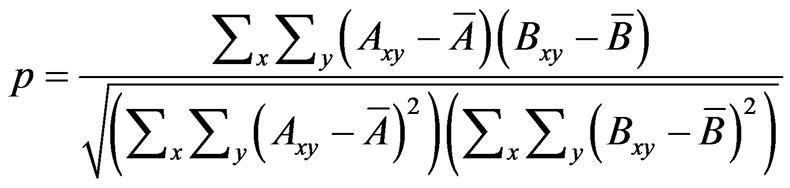
Formally, template matching can be defined as a method of parameter estimation. The parameters define the position of the template. We can define a template as a discrete function of Txy. Template matching uses a similarity criterion for locating an object, where one common method calculates a correlation coefficient using the following equation [11],
 (1)
(1)
where A and B are image matrices,  and ,
and ,  are the 2-dimensional means of the respective image matrices, and (x,y) are the spatial coordinates within A and B. This correlation coefficient closely resembles a traditional statistical correlation, with the difference being that the traditional method is calculated in one dimension instead of two dimensions. A high correlation coefficient in a pixel-by-pixel comparison between the template and the region of interest (ROI) indicates a good match. This “cross-correlation’’ yields a result only if the integral is computed over the whole area g. The basic idea behind the hit-or-miss transform is that of extracting all pixels within an image that are matched by a given neighborhood configuration, consisting of some arrangement of foreground pixels and back-ground pixels. The neighborhood configuration is therefore defined by a pair of disjoint sets: one for the foreground pixels and the other for the background pixels. This can be represented mathematically as:
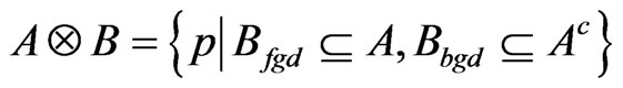 (2)
(2)
Where A is the image set, Ac is the complement of the image set, and B is the structure element. The algorithm flow chart is shown in Figure (2). Fixed templates are useful when object shapes do not change with respect to the viewing angle of the camera. Two major techniques have been used in fix template matching, image subtraction and correlation. In the first technique, the template position is determined from minimizing the distance function between the template and various positions in the image. Although image subtraction techniques require less computation time than the following correlation techniques, they perform well in restricted environments where imaging conditions, such as image intensity and viewing angles between the template and images containing this template are the same. Matching by correlation utilizes the position of the normalized cross-correlation peak between a template and an image to locate the best match. This technique is generally immune to noise and illumination effects in the images, but suffers from high computational complexity caused by summations over the entire template. Point correlation can reduce the computational complexity to a small set of carefully chosen points for the summations.
Dilation is one of the two basic operators in the area of mathematical morphology, the other being erosion. It is typically applied to binary images, but there are versions that work on grayscale images. The basic effect of the operator on a binary image is to gradually enlarge the boundaries of regions of foreground pixels (i.e. white pixels, typically) as shown in Figure (2). Thus areas of
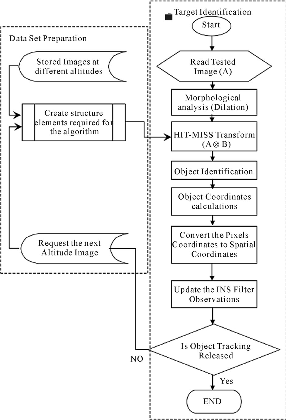
Figure 1. Example of template matching.

Figure 2. Dilation, grow or expand effect.
foreground pixels grow in size while holes within those regions become smaller. The dilation operator takes two pieces of data as inputs. The first is the image which is to be dilated. The second is a (usually small) set of coordinate points known as a structuring element (also known as a kernel). It is this structuring element that determines the precise effect of the dilation on the input image. To compute the dilation of a binary input image by this structuring element, we consider each of the background pixels in the input image in turn. For each background pixel (which we will call the input pixel) we superimpose the structuring element on top of the input image so that the origin of the structuring element coincides with the input pixel position. If at least one pixel in the structuring element coincides with a foreground pixel in the image underneath, then the input pixel is set to the foreground value. If all the corresponding pixels in the image are background, however, the input pixel is left at the background value.
3. Identification Results
The proposed method is simulated using Matlab program and the numerical experiments are shown to verify the object detection for a wide range altitude and orientation. The test image used is a satellite image includes two target objects. These targets are shown in Figure 3. The identification mechanism is tested at five altitudes, 8034, 7632, 7230, 7084, and 6888 feet respectively. The satellite images at different altitudes are shown in Figure 4. Each altitude is tested at different approaching angles, 0, 90, 180, 270 degree respectively. The generated templates for the two object after the hit/miss transform is shown in Figure 5. Figure 5 to 14 demonstrate the object (1) and object (2) identification and detection at different altitudes and orientation angles. The algorithm is evaluated on twelve different altitudes for two Objects. Figure 15 shows that the first object miss detection below 18% and false alarm detection below 6%. The second object with relatively large area satisfies results better than the first object which satisfies miss detection below 12% and false alarm detection below 4% as shown in Figure 16.
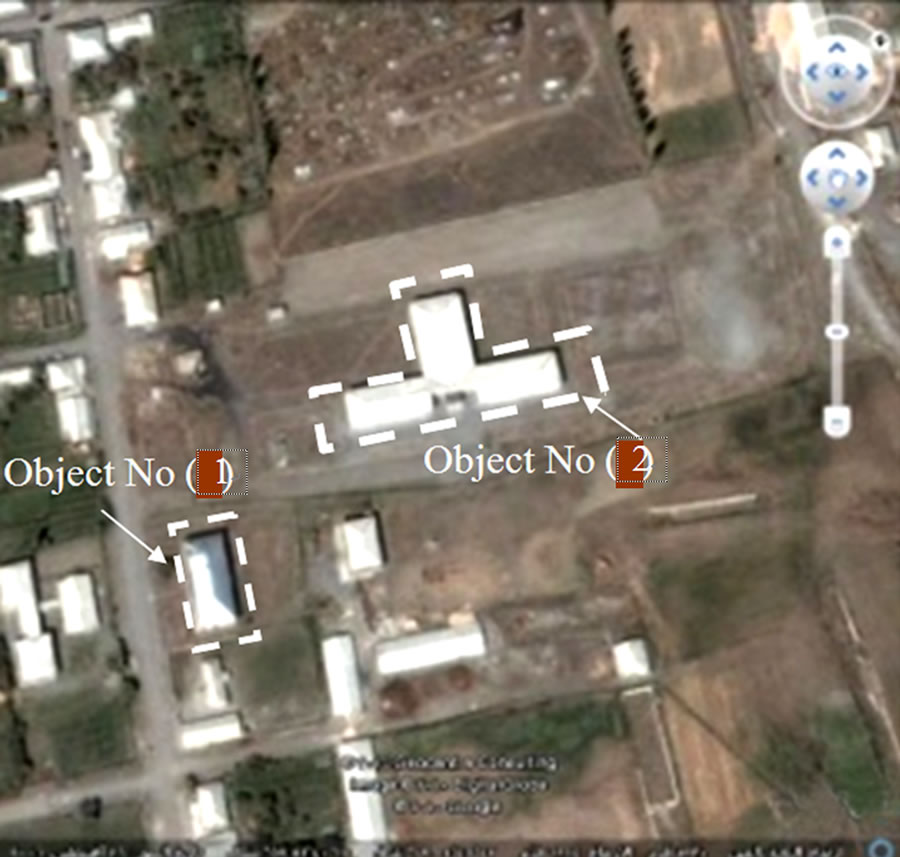
Figure 3. The satellite test image include the two targets.
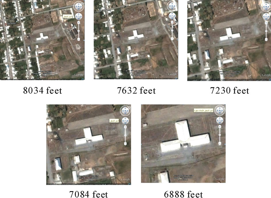
Figure 4. The satellite image at different altitudes.
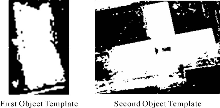
Figure 5. The two objects templates.
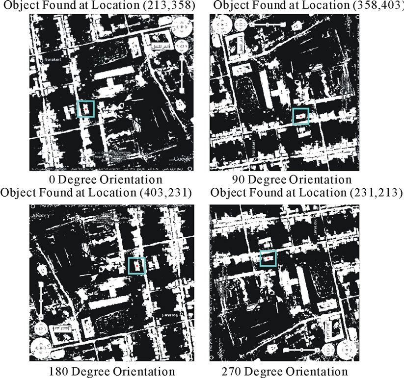
Figure 6. Object (1) detection at 8034 feet altitude.
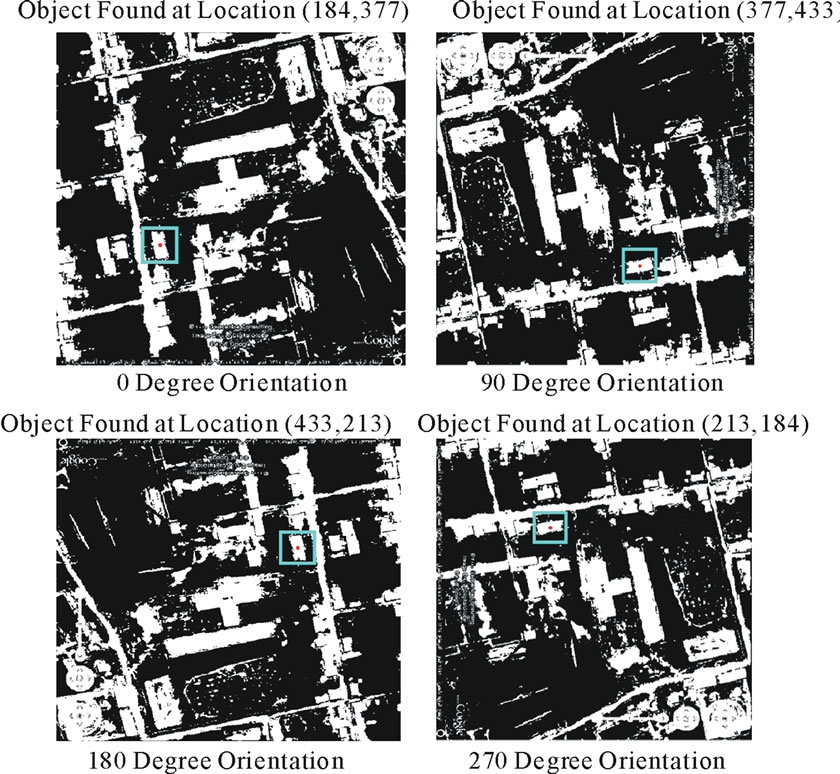
Figure 7. Object (1) detection at 7632 feet altitude.
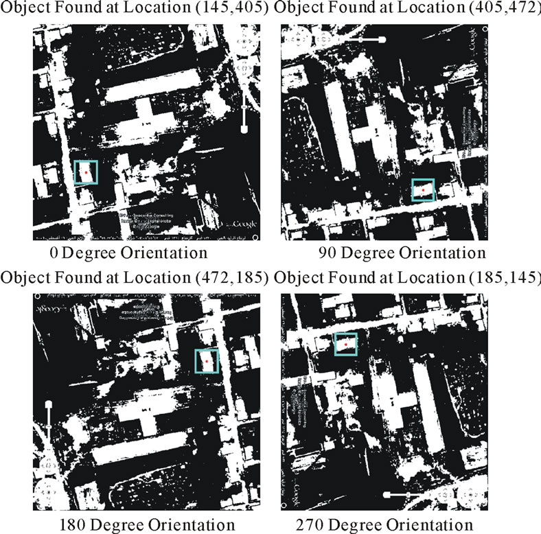
Figure 8. Object (1) detection at 7230 feet altitude.
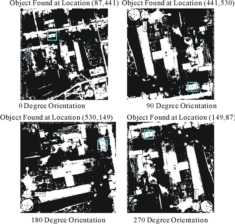
Figure 9. Object (1) detection at 7084 feet altitude.
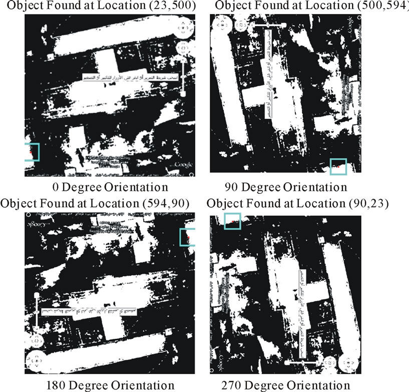
Figure 10. Object (1) detection at 6888 feet altitude.
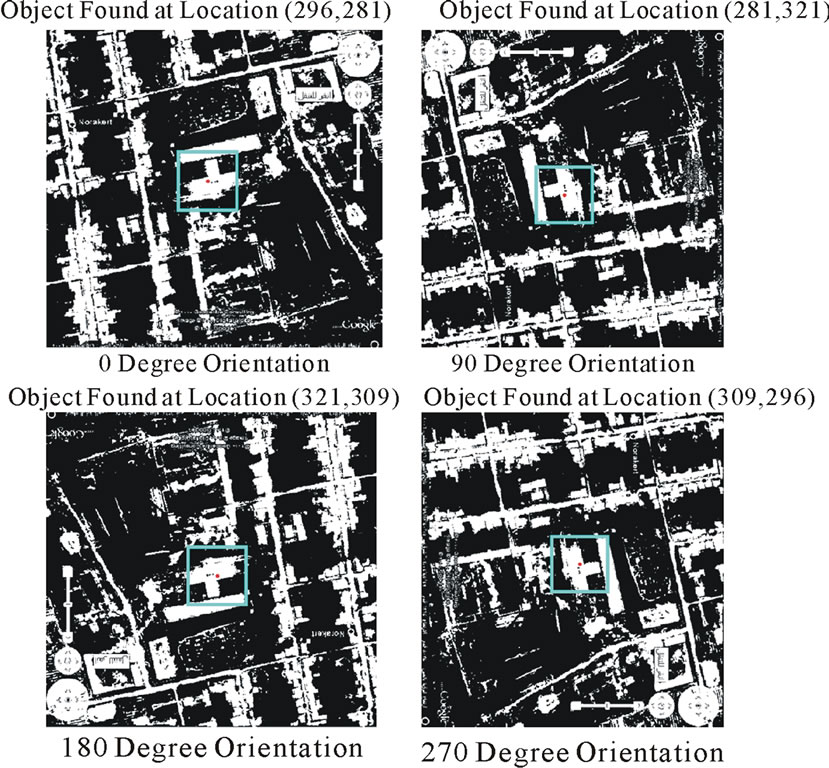
Figure 11. Object (2) detection at 8034 feet altitude.
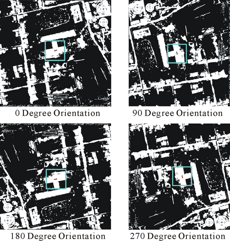
Figure 12. Object (2) detection at 7632 feet altitude.
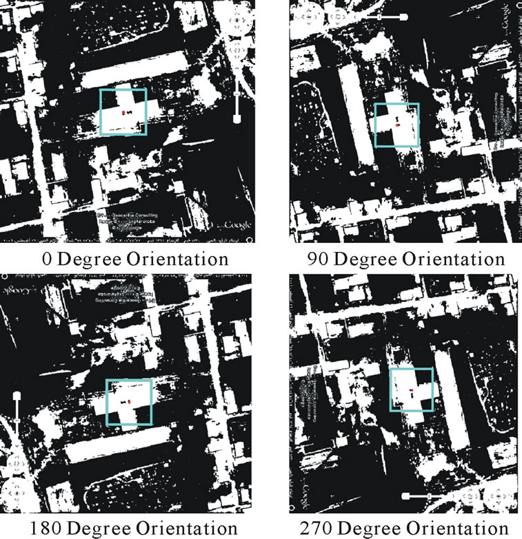
Figure 13. Object (2) detection at 7230 feet altitude.
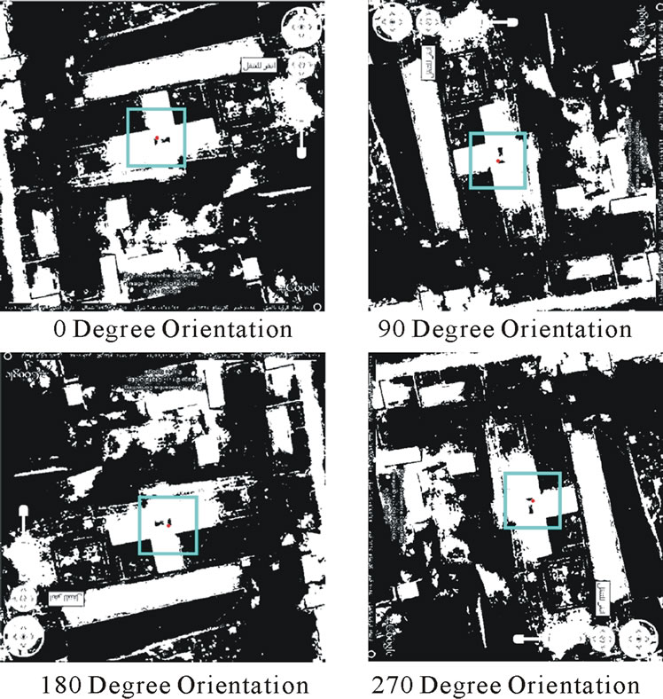
Figure 14. Object (2) detection at 7084 feet altitude.
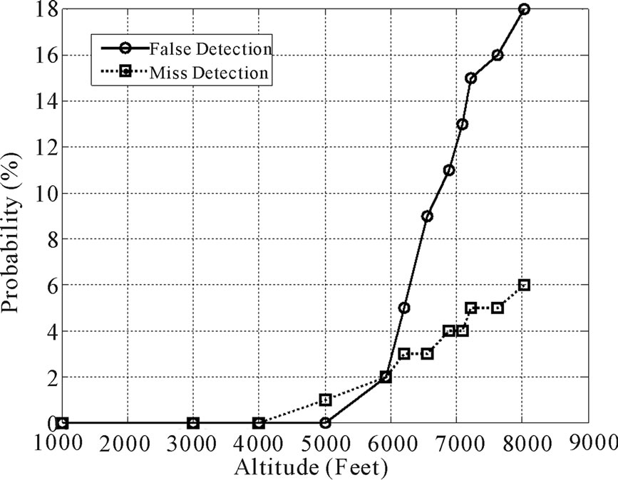
Figure 15. Object (1) detection at different altitudes.
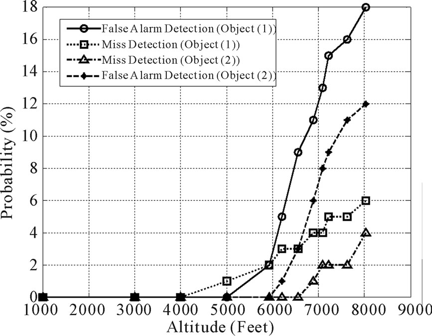
Figure 16. Object (2) detection at different altitudes compared with object (1).
4. Conclusion
This paper introduces a simple template match object recognition technique able to detect and recognize the ground objects in the stage of fine tuning the INS for flying vehicles. The proposed method is an image processing technique to improve the precision of the INS for detecting and tracking the ground objects. Template matching technique is one of the methods used for ground object detection and tracking. The paper focus is on flying systems equipped with camera to capture photos for the ground and recognize it. The proposed method is independent on the altitude or the orientation of the object. The system successfully recognized and detects the ground objects at different altitudes and orientation.
5. References
[1] Roger M. Dufour, Eric L. Miller and Nikolas P. Galatsanos, “Template Matching Based Object Recognition With Unknown Geometric Parameters,” IEEE Transaction on Image Processing, Vol. 11, No. 12, Dec. 2002. doi:10.1109/TIP.2002.806245
[2] Gupta, Rahul Gupta, Amardeep Singh and Matt Wytock, “Object Recognition using Template Matching,” http://www.stanford .edu/class/cs229 /proj2008.
[3] R. Brunelli, “Template Matching Techniques in Computer Vision: Theory and Practice,” Wiley, 2009. doi:10.1002/9780470744055
[4] Kyriacou, Theocharis, Guido Bugmann, and Stanislao Lauria, “Vision-based urban navigation procedures for verbally instructed robots,” Robotics and Autonomous Systems, Expanded Academic ASAP, No. 30, 2005.
[5] Zhao Yu-qian, Gui Wei-hua, Chen Zhen-cheng, Tang Jing-tian and Li Ling-yun, “ Medical Images Edge Detection Based on Mathematical Morphology,” Proceedings of IEEE Engineering in Medicine and Biology 27th Annual Conference Shanghai, China, September 1-4, 2005.
[6] Li, Y., Tsin, Y., Genc, Y. and Kanade, T., “Object detection using 2D spatial ordering constraints,” Computer Vision and Pattern Recognition, CVPR 2005. IEEE Computer Society Conference on, 20-25 June, 2005.
[7] Heisele B., Rocha C., “Local shape features for object recognition,” Pattern Recognition, 2008. ICPR 2008 19th International Conference on, Tampa, FL, 8-11 Dec. 2008
[8] Neal R. Harvey, Reid Porter, and James Theiler, “Ship detection in satellite imagery using rank-order grayscale hit-or-miss transforms,” Proc. SPIE, Vol. 7701, 2010.
[9] E. G. M. Petrakis, A. Diplaros, and E. Milios, “Matching and retrieval of distorted and occluded shapes using dynamic programming,” IEEE Transactions on Pattern Analysis and Machine Intelligence, Vol. 24, No. 11, 2002. doi:10.1109/TPAMI.2002.1046166
[10] Feng Ge, Tiecheng Liu, Song Wang and Joachim Stahl, “Template-Based Object Detection through Partial Shape Matching and Boundary Verification,” International Journal of Information and Communication Engineering, Vol. 4, No. 2, 2008.
[12] Rjiv Kumar Nathi, “On Road Vehicle/Object Detection Template,” Indian Computer and Science and Engineering, Vol. 1, No. 2, 2010.