Natural Science
Vol.4 No.11A(2012), Article ID:24874,13 pages DOI:10.4236/ns.2012.431118
Optimal ways of disposal of highly radioactive waste
![]()
Department of Civil, Environmental and Natural Resources Engineering, Luleå University of Technology, Luleå, Sweden; *Corresponding Author: drawrite.se@gmail.com
Received 21 August 2012; revised 24 September 2012; accepted 5 October 2012
Keywords: Hazardous Waste; Repositories; Crystalline Rock; Engineered Barriers
ABSTRACT
Multibarrier concepts are commonly proposed for effective isolation of highly radioactive waste (HLW). Present concepts consider the host rock as a barrier by retarding migration of possibly released radionuclides to the biosphere, containers for preventing release of radionuclides, and “buffer clay” embedding the canisters for providing ductility and minimizing the risk of container breakage and for delaying migration of possibly escaping radionuclides. Closer analysis of the isolating functions shows that rock will only serve as a mechanical protection of the “nearfield”, the containers of proposed types can be short-lived, and the surrounding clay will be increasingly permeable and stiffen hence becoming less ductile with time. A different approach, representing an alternative to the common concepts, can be safer and cheaper. It takes the HIPOW copper canister as the only major barrier and a cheap but sufficiently efficient buffer as embedment. The repository can consist of an abandoned copper mine, an option being to place HLW in emptied drifts while mining is still going in not yet exploited parts of the ore body.
1. SCOPE
Comprehensive research has been conducted since the eighties in countries like Sweden, Finland, France and the UK for developing methods for safe disposal of highly radioactive waste [1]. Most of the work has concerned crystalline rock, which provides excellent stability of repositories located at a depth of a few hundred meters but which makes prediction of groundwater flow and contamination difficult because of the high content of fracture zones. This problem has led to reduced faith in the waste-isolating capacity of rock and a tendency of relying on engineered barriers, as exemplified by the present paper. Currently proposed concepts for safe isolation of highly radioactive waste imply construction of deep repositories in crystalline, sedimentary or salt rock. Waste in the form of spent fuel is planned to be encapsulated in metal containers, termed canisters, surrounded by very dense smectite-rich clay, and placed in bored vertical holes or horizontal tunnels. The concepts favoured in Sweden and Finland are of multibarrier type with redundance provided by the host rock, canisters and the clay termed “buffer clay”. Despite the tremendous construction cost the planned isolation has several weaknesses and may not serve acceptably for the required 100,000 years. This matter is dealt with in the paper that describes an alternative concept for long-term safe isolation, implying only one type of effective engineered barrier and a potential to be implemented in abandoned mines or even—at a safe distance—in mines where mining is still going on.
2. PRINCIPLES FOR DISPOSAL OF HIGHLY RADIOACTIVE WASTE (HLW)
2.1. Rock
Because of the risk of erosion and other exogenic processes and the fact that the average hydraulic conductivity of rock decreases with depth there is general consensus that repositories should be located at a depth of at least some hundred meters [1]. Larger depth means that the rock stresses are higher and can cause collapse of deposition holes and tunnels. A risk that is particularly obvious if sedimentary rock is considered for hosting the waste. We will confine ourselves to consider only crystalline rock in this paper.
Structural modeling using the simple concept of plane, parallel fracture zones of different extension and width and assumed bulk hydraulic properties has been performed for calculating the contamination of groundwater that can occur if radionuclides are released from the waste containers [1,2]. The common spacing of major fracture zones, termed 2nd order discontinuities, is 100 - 1000 m, which makes it possible to fit in deposition tunnels and holes so that they will not interact with these major weaknesses. Smaller zones of 3rd order with lengths of 100 to 1000 m and spacings of 10 to 100 m, which are not allowed to intersect canister positions, will not be known until repository construction has begun [3]. Generalized structural models will look like the one in Figure 1.
2.2. Engineered Barriers
2.2.1. Presently Considered Canisters for Spent Fuel
Figure 2 shows the engineered barriers according to most of the proposed concepts for isolating HLW from the groundwater. There is only one criterion for waste containers of HLW, i.e. the canisters, except that they must be constructible and reasonably costly, and that is that they must be tight for a very long period, usually taken as 100,000 years. For this purpose they must not be through-corroded or broken in this period, which puts demands on the chemical integrity and mechanical strength.
Internationally, steel canisters are a primary choice due to their mechanical strength and because the oxygenfree conditions at deep-geological disposal suggest that corrosion will not be significant [1]. In Sweden and Finland canisters consisting of a core of cast iron with room for spent fuel and surrounded by a 50 mm copper lining is favoured [2]. The iron core, separated from the lining by a 2 mm space, provides mechanical strength and the copper liner corrosion protection.
One problem with the iron/copper canisters is their sensitivity to rock strain. They must sustain seismically or tectonically transversal shearing and resist axial tension caused by movements in that direction of the surrounding buffer clay. Transversal shearing indicated in
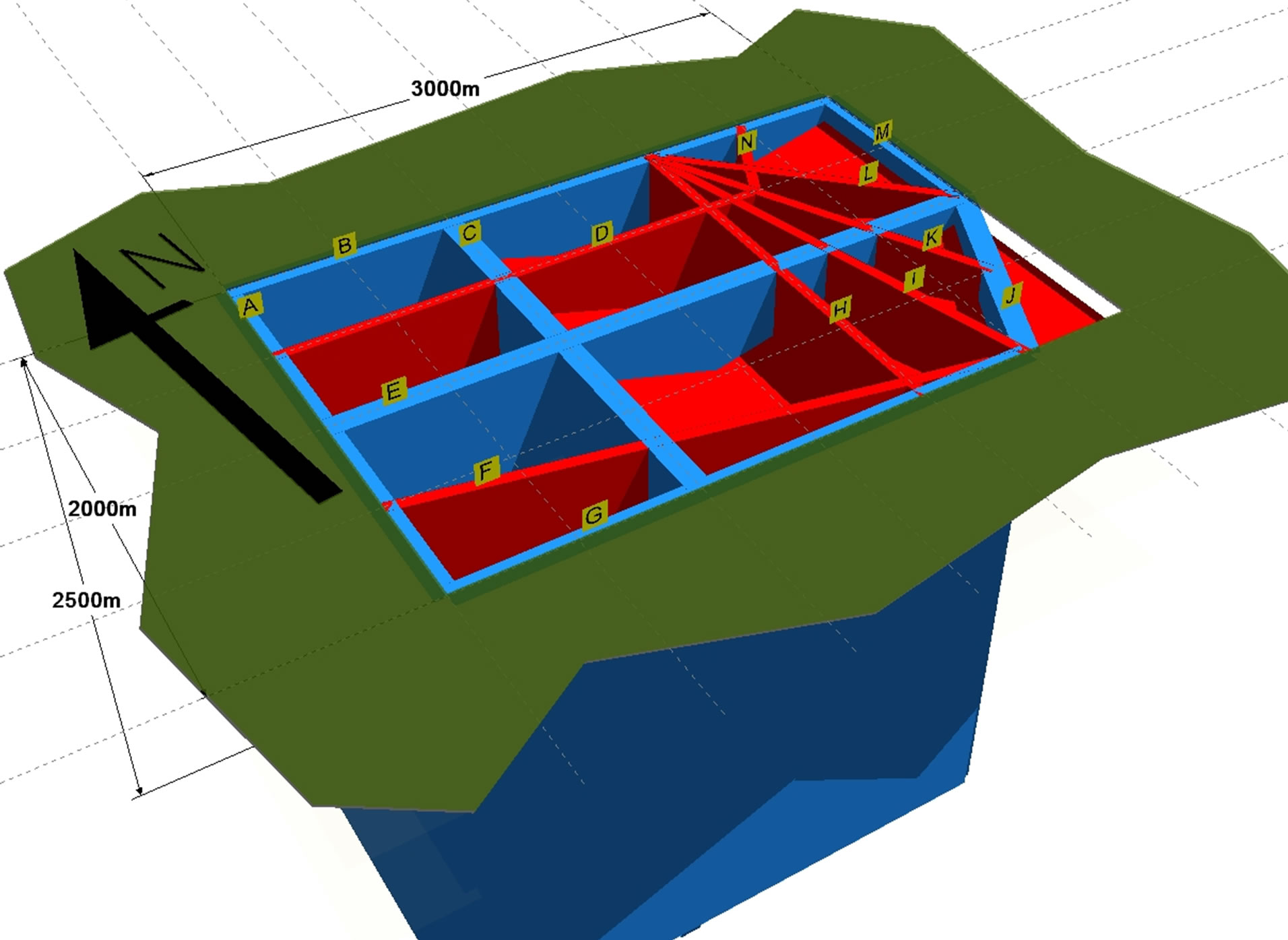
Figure 1. Simplified and generalized model of candidate site. The green area represents the ground surface and the blue plates 2nd order discontinuities with 100 m width. The red plates are 2nd and 3rd order discontinuities with 50 m width. No repository tunnels and rooms have been marked [3].
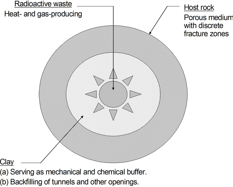
Figure 2. Isolation of HLW. The radioactive waste is contained in canisters (inner circle) embedded in “buffer” clay that fills up the deposition hole bored in rock [4].
Figure 3, can take place along a fracture or fracture zone. The Figure refers to Swedish and Finnish canisters with an inner core of cast iron with channels for the spent fuel, surrounded by a copper liner separated from the core. The ductility of the clay “buffer” surrounding the containers reduces the stresses generated by the shearing but calculations have shown that there is a critical condition with respect to shear strain as indicated in the figure.
2.2.2. Buffer Clay
The hydraulic conductivity of the clay surrounding the canisters and also of the tunnel backfill waste shall, by definition formulated by the Swedish and Finnish organizations, SKB and POSIVA that are responsible for long-term safe isolation of HLW, be lower than of the surrounding rock. The clay must be expandable for supporting the surrounding rock and be able to carry the heavy containers without yielding and at the same time be sufficiently soft to moderate stresses generated in the canisters by seismic and tectonic movements.
Commercially available smectite-rich clays dominated by the clay mineral montmorillonite are being selected by SKB and POSIVA for the Swedish and Finnish HLW repositories [2]. Buffer clay in the form of dense blocks manufactured by compacting air-dry smectite granules will be stacked in the deposition holes or tunnels and surrounded by loosely filled granules. The granules in the blocks and filled buffer consist of very large numbers of particles (“lamellae”) with one octahedral sheet (O) and two tetrahedral sheets (T) as shown in Figure 4, in which one sees interlamellarcations such as Na+, Ca2+, Mg2+, K+, and H2O or other inorganic or organic cations and molecules. Al3+ in the octahedral sheet can be substituted by Mg2+ and Fe2+ or Fe3+ and Al3+ and Fe3+ can also substitute for Si in the tetrahedral sheet. These
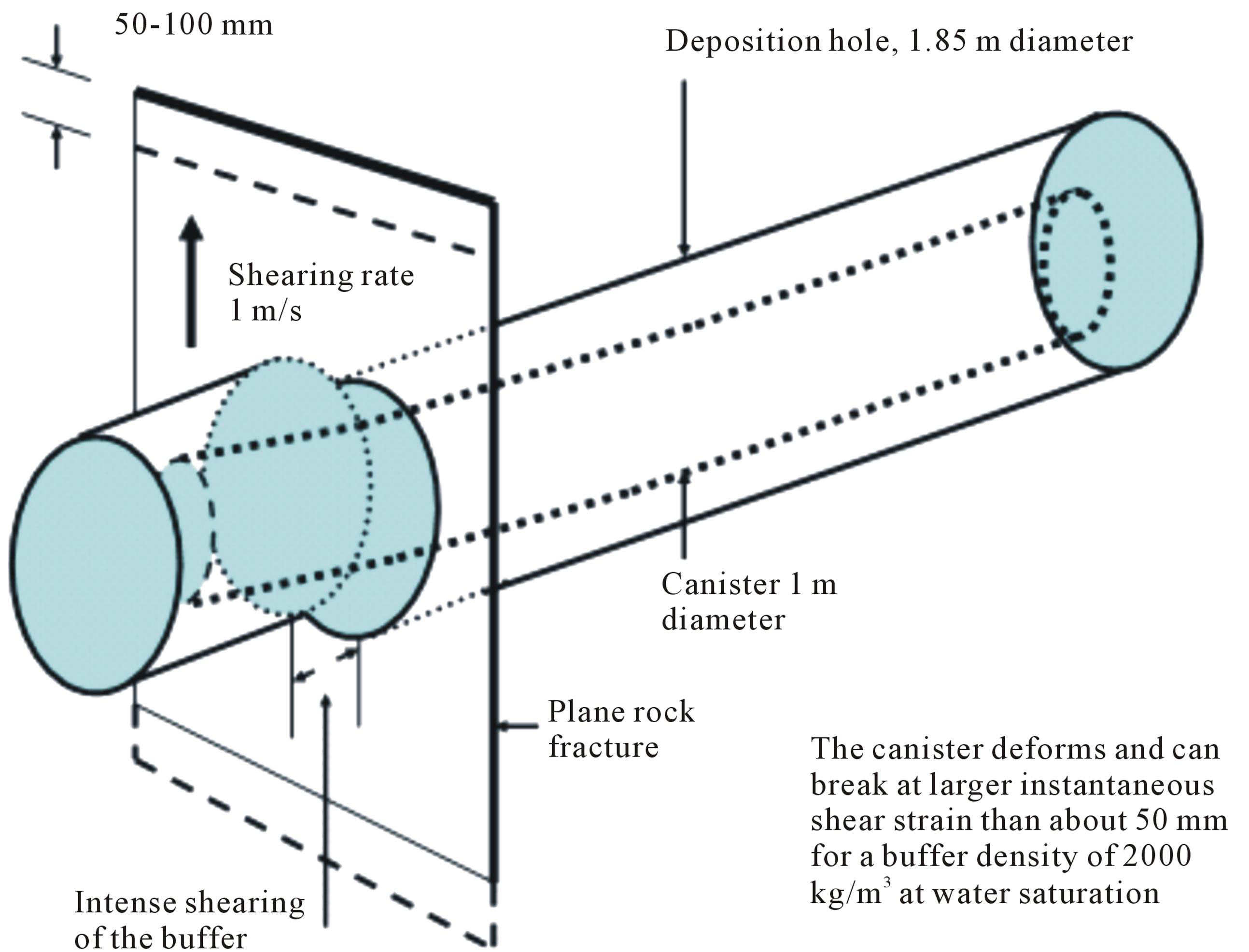
Figure 3. Calculated deformation of clay-embedded canister in horizontal deposition hole that is intersected by a steep fracture along which a 0.1 m tectonically induced, instant shearing takes place [4].
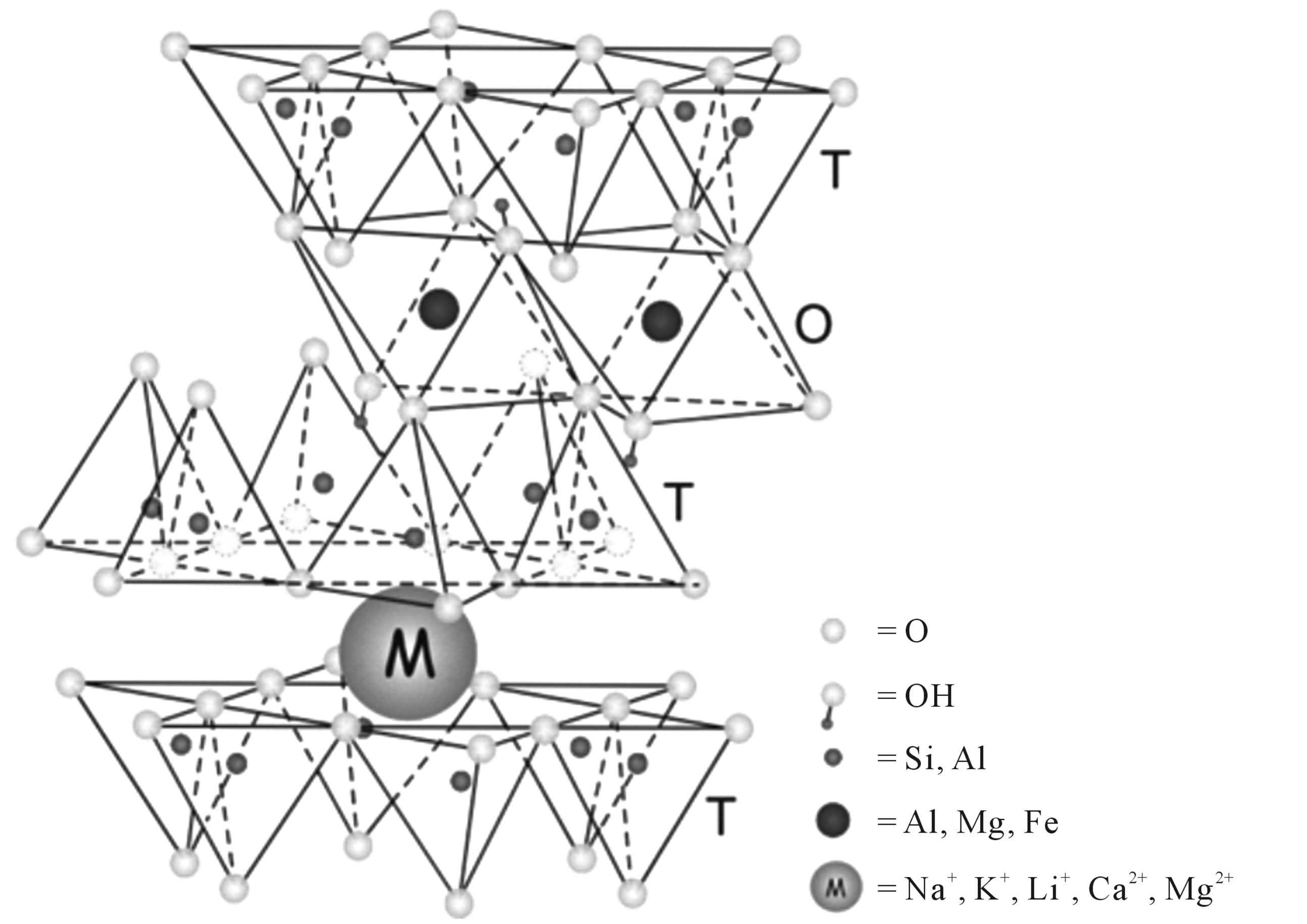
Figure 4. Crystal structure of the smectite species montmorillonite. M is an exchangeable cation connecting sheets of silica/oxygen tetrahedrons (After Güven). Water molecules are associated with the cation and form up to three water layers.
non-stoichiometric substitutions give a negative surface that is balanced by exchangeable cations absorbed between the TOT-lamellae and around the particle edges. Water molecules form hydration shells surrounding the exchangeable cations in the interlamellar space, giving smectites their expandability. The smectite species montmorillonite, favoured by the Nordic organizations, with Na in the interlamellar space can have 1, 2 or 3 interlamellar hydrates causing a swelling pressure of a few hundred kPa for 3 hydrates and more than 10,000 kPa for a mono-hydrate.
For the common buffer density of about 2000 kg/m3 at water saturation the hydraulic conductivity is as low as 5E−13 to 5E−12 m/s because the interlamellar water is high-viscous and the interparticle voids very small and their interaction poor. If Ca or any other bior trivalent cation replaces Na in soft parts of the heterogeneous microstructural network the net bulk conductivity increases by about one order of magnitude. The swelling pressure exerted on the canister is on the order of 2 - 5 MPa depending on the density, smectite content and groundwater chemistry [4].
3. PERFORMANCE OF THE BARRIER SYSTEM
3.1. Rock
3.1.1. Hydraulic and Mechanical Functions
The plan followed for locating the repository so that it becomes adapted to the structural constitution of the host rock, illustrated by Figure 1, will turn out to be academic and impossible to implement as intended. Thus, unforeseen fracture zones will be met with and strong local inflow of groundwater when passing through 2nd and 3rd order discontinuities will make the construction difficult, forcing the designers to abandon the planned positions of deposition tunnels and canister holes. The final form of the repository of Nordic type will be as shown in Figure 5, which indicates that the degree of utilization of the rock mass may be as low as 50% and not exceed 70%. The cost for excavation and drilling pilot holes for locating tunnels and holes and doing all the largely unreliable calculations of the overall hydraulic performance and migration of possibly released radionuclides will still be high.
There will be difficulties in deciding location and orientation of the deposition tunnels with respect to the presence of fracture zones and when the geometry has to be decided one still does not know the existence of fracture zones and discrete fractures that will determine the hydraulic and mechanical performance of the near-field rock (Figure 6). This graph applies also on a large scale, meaning that fracture zones adjacent to tunnels will generatehigh hoop stresses and EDZ effects that raise the axial hydraulic conductivity along the tunnels. Such zones may never be found but are still causing problems.
The radionuclide transport capacity of the rock is determined by its hydraulic transmissivity, which is controlled by the interconnectivity and hydraulic conductivity of the system of discontinuities. This system does not have the form of regularly spaced plane slots but appear as networks of fine openings with varying aperture. The geometry is in fact largely hypothetic since it is not possible to work out detailed structure models and to get accurate data of the respective weaknesses until the repository has been constructed. The possibility of making trustworthy calculation of groundwater flow in crystalline rock with its spectrum of permeable features is in fact very small. As realized in an EC project on disposal of hazardous waste in abandoned mines, only the major discontinuities, i.e. the fracture zones, can be ascribed hydraulic conductivities and transmissivities that make
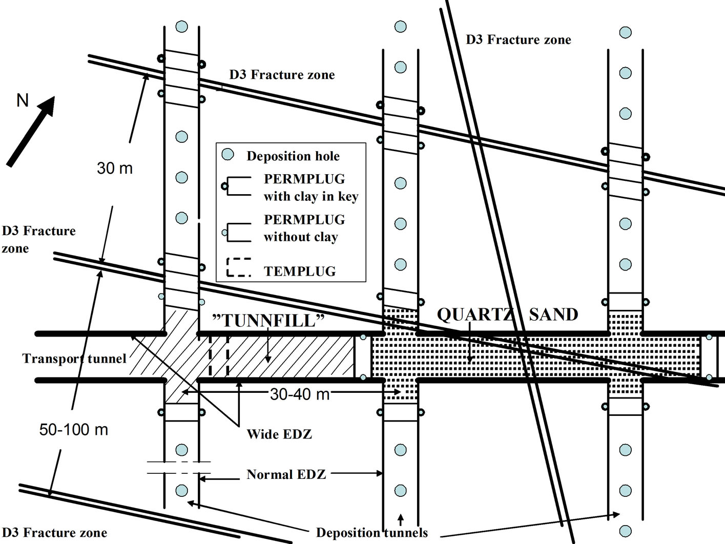
Figure 5. Schematic plan view of a KBS-3V repository with a transport tunnel connected to deposition tunnels in rock with typical frequency of 3rd order fracture zones. Tight plugs keyed into the rock for isolating the tunnels with waste containers (small circles) from fracture zones and from transport tunnels [3,4].
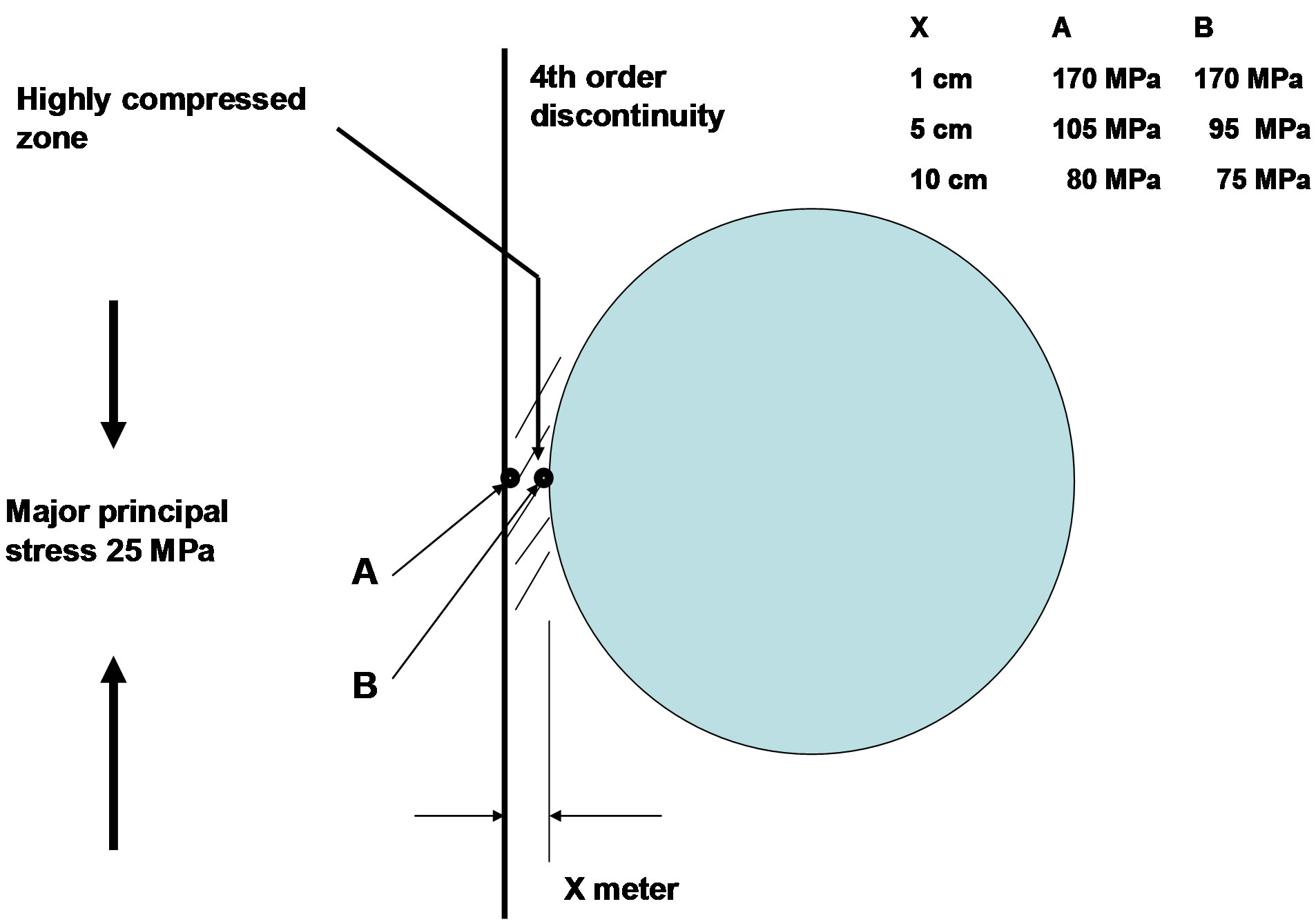
Figure 6. Compression of rock tongue formed between a major fracture—4th order discontinuity—and the periphery of a deposition hole or tunnel. For an assumed diameter of 1 m, a thickness (x) smaller than a few centimetres causes breakage even at moderate average rock stresses [3,4].
gross flow calculations relevant [5]. This project led to the conclusion that groundwater flow primarily takes place in crossings of such zones (Figure 7). This makes commonly performed predictions of the transport of water carrying contaminants largely hypothetic.
3.1.2. Stability Issues
The in-situ rock stresses increase with the distance from the ground surface and can become critically high at large depth. Lateral stresses can be high also at shallow depth and they are locally more than 40 MPa in the region where the Swedish HLW repository is now under construction. Taking the laboratory-determined unconfined compressive strength, 150 - 350 MPa, as parameter for assessing hole positions, application of statistical methods has shown that a few percent of them have to be abandoned in the process of detailed design. This is still an underestimation since the impact of scale on rock strength is not taken into consideration. It can signifcantly reduce the number of acceptable positions of deposition holes [6].
The impact of disturbance of the hydraulic performance of a rock mass by the construction work is important and not yet properly considered by repository designers. There are two in fact, one due to rock damage by the excavation process, which is commonly blasting, and the other by compression, expansion and shearing of existing discontinuities in the rock around the tunnels and holes. The thermal puls caused by the evolution of heat due to the radioactive decay adds changes in its structure and hydraulic and mechanical performances.
Very tight rock, which would appear to be ideal for locating a HLW repository, is commonly under high pressure implying that the immediate surroundings of tunnels, holes and shafts will be under very high stress

Figure 7. Groundwater flow in fracture zones is quickest in their crossings as illustrated by the calculated distribution of concentration of contaminants. Radionuclides released from canisters can hence appear very early in fracture zones far from thee repository. Flow takes place from left to right in the figure [5].
that are magnified by thermal effects. The maximum heave of the ground surface above a repository with 6000 waste containers, each with 600 W power, will be about 200 mm [7], causing shearing of 3rd order fracture zones and changes in aperture of discrete fractures. Many of these in the upper hundreds of meters will be significantly widened and cause a rise in bulk hydraulic conductivity.
Excavation of repository rooms can be made by blasting, which is proposed for the Swedish HLW repository, or by TBM boring. The latter technique causes hoop stresses that can generate failure, while blasting has the effect of relaxation but also formation of a disturbance zone (EDZ) with a hydraulic conductivity that will be at least 100 times higher than for virgin rock down to about 1 m below the tunnel floor, and 10 times in the walls and roof [3]. The EDZ has an E-modulus that can be less than 1/100 of that of virgin rock [7]. This all means that the hydraulic and mechanical performances of the repository host rock will be quite different from what predictions based on simplified and incomplete structural models tell us. On top of this comes the impact of seismic and tectonic impacts as well as of the everlasting massage of the earth crust caused by tide effects.
The conclusion of all this is that the host rock of a deep geological repository does not perform as a barrier to transport of radionuclides but merely as a mechanical protection of the “chemical apparatus” if the primary rock stress conditions are suitable.
3.2. Canisters
The sensitivity of the described type of iron/copper canisters to chemical attack and to even small strain is particularly obvious when considering the role of the buffer clay. This is the main argument for the alternative concept for disposal of HLW proposed in this paper.
The risk of through-corrosion is largely neglected by the organizations promoting the iron/copper canister. Applying ordinary chemical laws and neglecting strain of the type illustrated by Figure 8, it is claimed that the 50 mm copper liner will not have thoroughgoing corrosion holes until after 100,000 years. Considering the combined impact of strain and dissolution of the copper this estimate is not on the safe side. An additional risk of early failure can be caused by the so far neglected impact of electrical fields in host rock located near high-voltage transmission lines [3]. Intense corrosion has in fact been found of instruments like packers in the granite region where the Swedish HLW repository is now being constructed at Forsmark, north of Stockholm. If such corrosion hits the iron/copper canisters the thin copper liner may be totally corroded in a century or less than that. This risk has not been ruled out.
The degradation of the host rock to be just a mechanical protection of the “near-field”, and the long-term isolation of HLW to be limited for iron/copper canisters reduces the number of effective barriers to just one: The buffer clay. An alternative approach, proposed here, is to use totally tight canisters of other type, and to consider

Figure 8. Cross section of SKB deposition tunnel with canister embedded in expansive clay. Axial tension of the canister by upward expansion of the buffer clay at its upper part in conjunction with compression of the tunnel backfill will take place. The lower and central parts of the canister are firmly held by the clay [4].
the buffer as a deformable, somewhat expandable embedment of the canisters for minimizing the stresses in them without providing tightness.
3.3. Buffer Clay
The hydrothermal conditions prevailing for many hundred years in the “buffer” regions of a repository will affect the clay in several ways. The initially only partly water saturated clay will undergo desiccation and fissureing and the subsequent saturation by uptake of groundwater from the rock, which can take centuries, is associated with accumulation of precipitated salt (Figure 9). This process proceeds as long as there is a temperature difference between the hot canister (100˚C) and the rock and can make the clay temporarily tight. In a real repository the temperature gradient will finally be evened out or redirected causing dissolution of the precipitations, which will raise the hydraulic conductivity.
The most extensively investigated impact on smectite clays by heating is dissolution and alteration of the smectite minerals and precipitation of silicious compounds. There is general consensus on the validity of the empirical reaction formula Eq.1, [8].
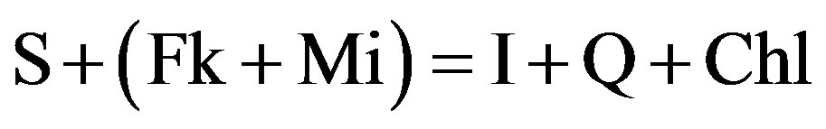 (1)
(1)
where: S: denotes smectite; Fk: K-feldspars; Mi: micas; I: llite; Q: quartz; and Chl: chlorite.
Illite is formed from smectite by uptake of potassium emanating from accessory minerals or from the groundwater. The evolution is via mixed-layer stages or by neoformation through interacting silica, aluminium and potassium released from dissolving minerals or provided by the groundwater [9]. Interaction of smectites and waste containers has been investigated in detail. For copper canisters the impact on either of them is claimed to be insignificant at larger distance than a few millimetres from the canister surface [2]. Clay for surrounding containers of steel, which are considered for HLW disposal in other countries than Sweden and Finland, is in focus internationally and the most recent study on the interaction of smectite clay and steel and iron has significantly deepened the understanding of the longevity of

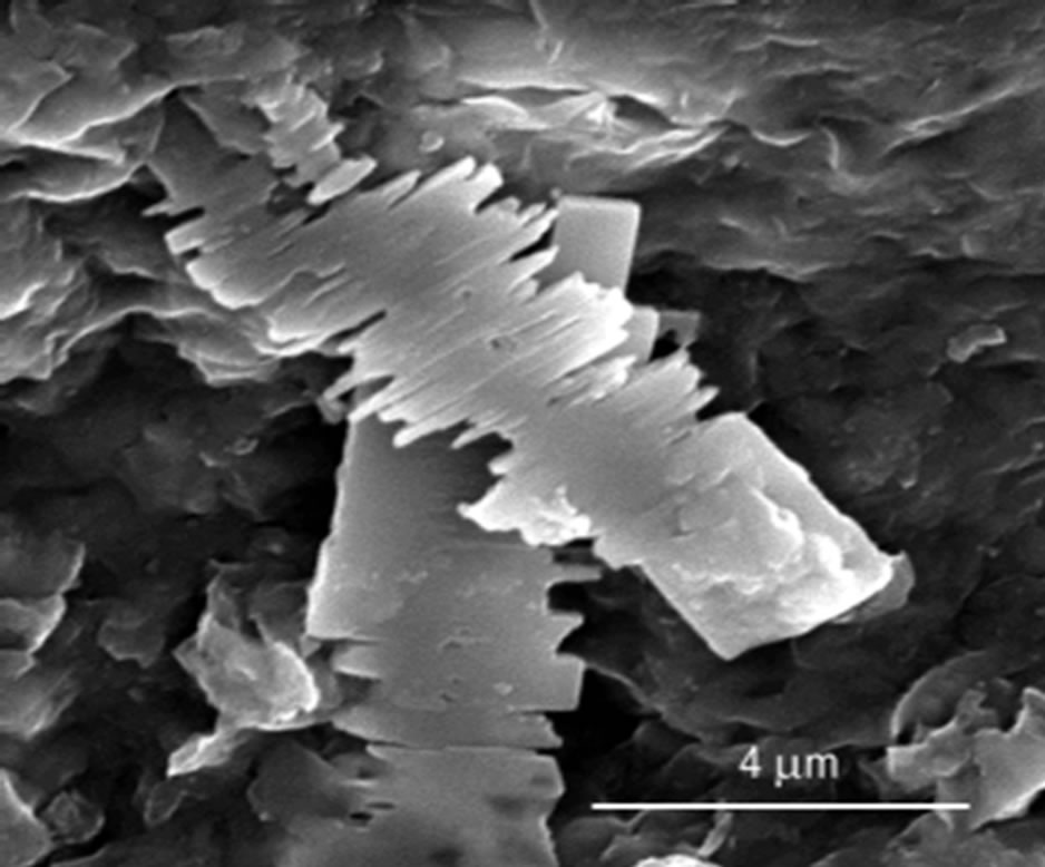
Figure 9. Examples of salt precipitation adjacent to the hot HLW canisters. Left: NaCl precipitated in 10 µm cavity. Right: Gypsum filling a large cavity.
smectite clay in contact with this metal [10]:
• For montmorillonite there are two reaction directions: “illitization” in open reaction systems and “smectitization” in closed systems. The degree of alteration is controlled by the concentration of free Fe and Si. Oxidation of native iron is the main driving force for dissolution and subsequent Si-precipitation.
• Illite is formed close to the steel container and kaolinite or pyrophyllite farther away via smectitization. The “illitization” process results in higher interlamellar charge and lower swelling pressure. In contrast, the formation of smectite reduces the interlamellar charge and increases the swelling pressure.
• Uptake of Fe in the octahedral sheet, replacing Al, can accelerate alteration of smectites because these large ions cause high crystal stresses and instability.
• Enhanced temperature raises the Fe-activity and the amount of dissolved Si at the clay/canister interface causing strong precipitation of Si. Ion exchange from Na to Fe collapses the clay/water system and widens voids. This promotes channel-like transport of solutions (Figure 10). In a very long time perspective cementation by precipitation of Si can convert smectite clay to shale [3,9].
Considering the iron/copper canister formation of corrosion holes or fractures in the copper liner will let water in to the iron core where well known reactions will start. Hydrogen gas under high pressure will be formed and cause fingerlike channels in the surrounding buffer if its tightness with respect to gas is low or a high-pressure gas bubble at the surface of the canisters if the buffer is gas-tight. Fe resulting from iron corrosion will react with the buffer as described.
Models describing the long-term conversion of montmorillonite, being the expansive clay mineral of primary interest to Nordic designers of HLW repositories, indicate that at least 75% of this mineral will be retained after a few thousand years if the temperature does not exceed 100˚C, assuming the activation energy to be 27 kcal/mole [4,8]. Since the temperature will drop with time it is estimated that at least 50% of this clay mineral will remain after ten to hundred thousand years. A problem arises, however, if the stiffening by precipitation of silicious matter (Eq.1) will reduce the expandability and ductility as indicated by hydrothermal tests on laboratory and bench scales [3,4].
4. WAYS OF PROVIDING SAFER AND CHEAPER DISPOSAL OF HLW
4.1. The Bearing Principle
One of the conclusions from an EU project termed “Low Risk Deposition Technology (LRDT)” [5] was that deep abandoned mines can serve very well for disposal

Figure 10. Model of microstructural changes caused in hydrothermally heated smectite clay [4]. The stacks of lamellae contract in the hot buffer by which the voids become wider, and precipitation of silica causes cementation that prevents spontaneous return to the original state.
of hazardous waste. The principle was to assemble waste containers in stable drifts and embed them in dense expandable clay, Figure 11. A problem with this and the Nordic concepts for HLW disposal is that pH of ordinary concrete is about 13 and degrades contacting smectite clay, and that conventional organic superplasticizers for making the concrete fluid can produce colloids that can carry and disperse radionuclides. They are therefore ruled out in modern repository design.
The risk of tectonically generated rock strain that can affect the integrity of waste containers depends on the size of the repository rooms, which is of importance in considering use of abandoned mines for disposal. Large ones will undergo earlier and larger shear strain that will affect a higher number of waste containers than in smaller drifts. Also, the EDZ of large drifts and rooms is deeper and more pervious than of drifts of smaller dimensions and the risk of migration of possibly released radionuclides to flowing groundwater is obvious. It can be compensated by using more effectively isolating engineered barriers.
The conditions for predicting groundwater flow in rock with mined-out rooms and drifts are different from those for new repositories. For the latter it has been shown that the volume of drill cores taken for making a structural model of the host rock is about 0.000001% of the total volume giving a hypothetic rock structure model. In contrast, the number of boreholes used for locating drifts and rooms for exploitation of the ore bodies in a mine is large; there are often several hundreds or even thousands of exploration holes and the rock structure model is hence very well founded. Theoretical modeling for predicting possible groundwater contamination by
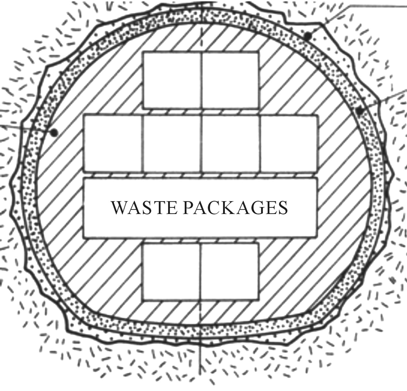
Figure 11. Drift with 5 - 10 m height and width for disposal of hazardous waste (LRDT concept, [5]). The rock surfaces are shotcreted with lowpH concrete (upper pointer) to give a smooth contour for installation of tightly fitting blocks of dense buffer clay (right pointer) parallel to placement of containers (left pointer).
radionuclides can therefore be made more adequately than for new repositories.
There are negative arguments as well: the EDZ will be more extensive and conductive than for new repositories because of the effective demolishing that is required for releasing ore. A further difficulty is that the usually irregular shape of drifts and rooms makes rational placement and isolation of waste and waste isolation more difficult. However, a mine would provide the same mechanical support of the canisters as a new repository constructed by blasting at a much lower cost.
4.2. Effective Engineered Barriers
4.2.1. Canisters
The fact is that the uncertainties respecting long-term isolation of the waste in crystalline rock using presently proposed repository concepts are very significant and that more reliable engineered barriers are required. The most important barrier that comes in focus is the canister. Steel canisters will have a negative chemical impact on smectitic clay buffer and do not qualify as well as those of copper. The iron/copper canister has weaknesses, however, primarily by the risk of failure by the very high swelling pressure exerted on it in combination with tension caused by the upward expanding buffer around the upper part of the canister. An ideal solution would be to use the HIPOW type of copper canisters, which are prepared by high-temperature compaction of copper powder with spent fuel distributed in it. The technique has been tested on nearly full scale and it has been shown that the porosity of such copper is in fact lower than that of cast copper metal (Figure 12). Further refinement is required for implementation but the creators see this technique of preparing copper canisters as feasible [11].
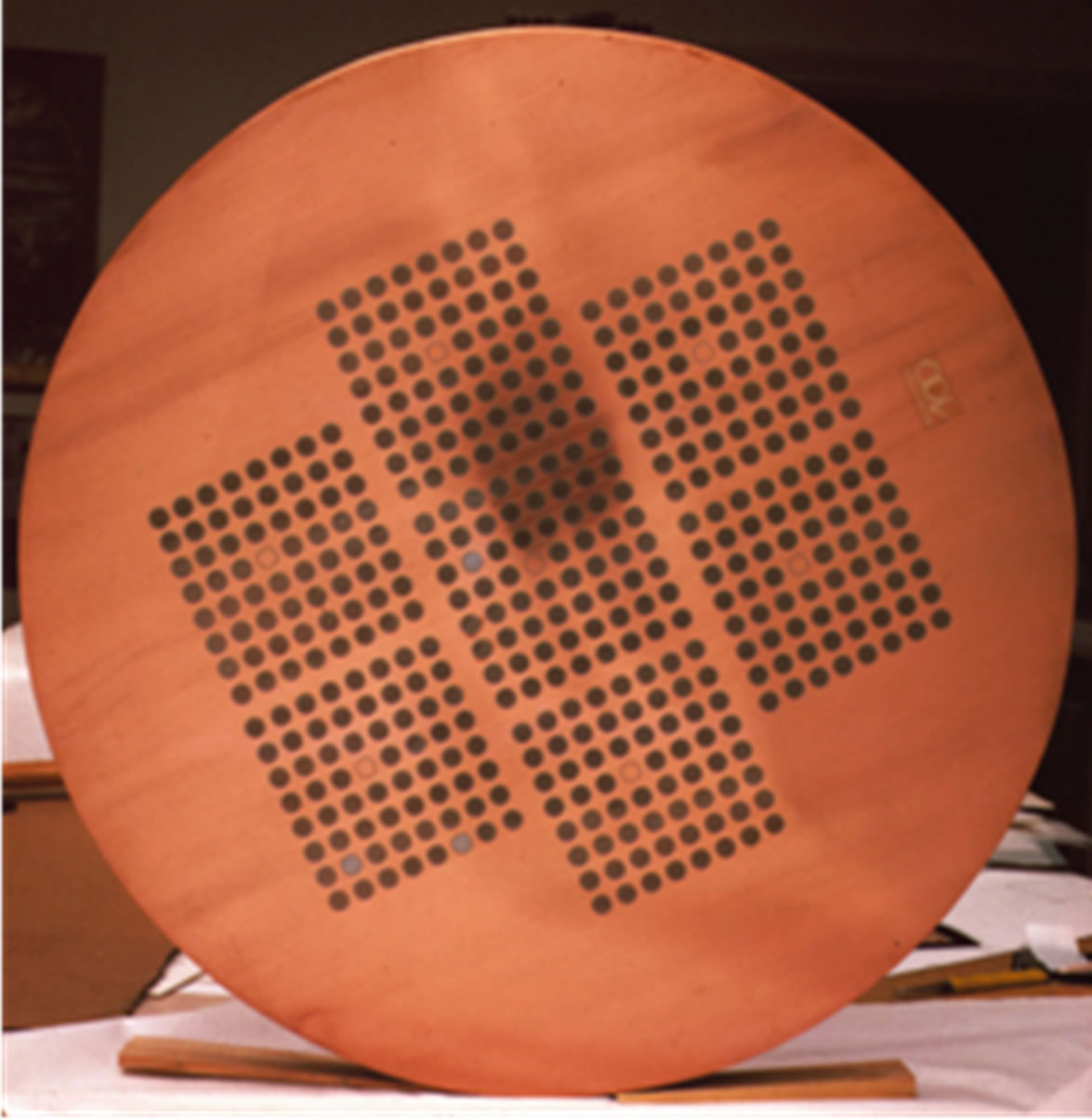
Figure 12. Disc sawn from a 1.6 m long column of HIPOW-compressed copper powder in a copper tube. The spent fuel, simulated by steel pellets in the experiment, is the black spots in the copper mass. Diameter about 600 mm [3,4].
The advantages of copper canisters of HIPOW type are obvious: Pitting corrosion will not reach deeper than 50 mm in 100,000 years and it would hit only a few fuel rods in this period of time. Total corrosion would take many millions of years. Considering the possible risk of fast corrosion caused by the impact of electrical fields generated by high-voltage transmission cables, the massive copper canister would be much more resistant than the presently proposed 50 mm liner. The difference is manifested by the calculated depth of corrosion of the copper, which exposes the waste content at least one million times later for the HIPOW canister than for the presently proposed copper-shielded iron canister [3]. The ductility of the 100% HIPOW copper canister is estimated to make it sustain an instantaneous shear strain of at least 3 times the critical strain of the iron/copper canister (cf. Figure 3).
4.2.2. Buffer Clay
The presently used models for chemical degradation of smectite clays give values of the degree of conversion that strongly depend on the selection of certain parameters, especially the activation energy for this process. For the non-conservative value 27 kcal/mole most of the smectite will remain in a 100,000-year perspective, while values claimed to be evaluated from experiments and natural evidence imply total conversion to non-expandable minerals in a few hundred years [1]. There are indications that certain smectite species are more resistant to high temperature than montmorillonite, which has been investigated in short-term laboratory experiments. Three clays, one rich in montmorillonite (MX-80), one with saponite as dominant mineral, and one consisting of mixed-layer smectite/illite/chlorite (Friedland) were prepared by compacting air-dry powder in hydrothermal cells of stainless steel with one end made of copper. This end was heated at about 95˚C for about six weeks, while the opposite end, separated from the steel and located 50 mm from the hot end, was kept at 35˚C by circulating 1% CaCl2 solution through a filter (Figure 13) [3,4].
At termination the samples were sectioned and the distribution of Cu determined by EDX technique as shown by Figure 14. One sees that saponite and mixed-layer clay with the same density had less uptake of copper ions than equally dense smectite-rich clay (MX-80). Comparing the physical properties the mixed-layer clay, having the lowest smectite content, underwent less changes than the others.
Figure 14 shows that while copper migration was obvious in the montmorillonite clay and noticeable in the mixed-layer clay it was absent in saponite. The samples were also tested with respect to their physical properties and the conclusion was that the hot montmorillonite sample showed a significant loss of expandability and a rise in hydraulic conductivity by 100 times. The physical properties of the saponite changed much less than for montmorillonite. The expandability of the hottest part remained high and was roughly the same as in untreated saponite clay in the central and cold parts. The hydraulic conductivity of the hot part was about 70 times higher than of untreated saponite but had only risen slightly in the central and cold parts. The hydraulic conductivity of the hot mixed-layer clay was about 50 times higher than of untreated clay but remained unchanged in the central

Figure 13. Small-scale simulation of the conditions for hydrothermal impact on buffer clay. The cold end of the cell with clay was kept at 35˚C by circulating CaCl2 solution through the upper filter, while the hot end of copper was kept at 95˚C.
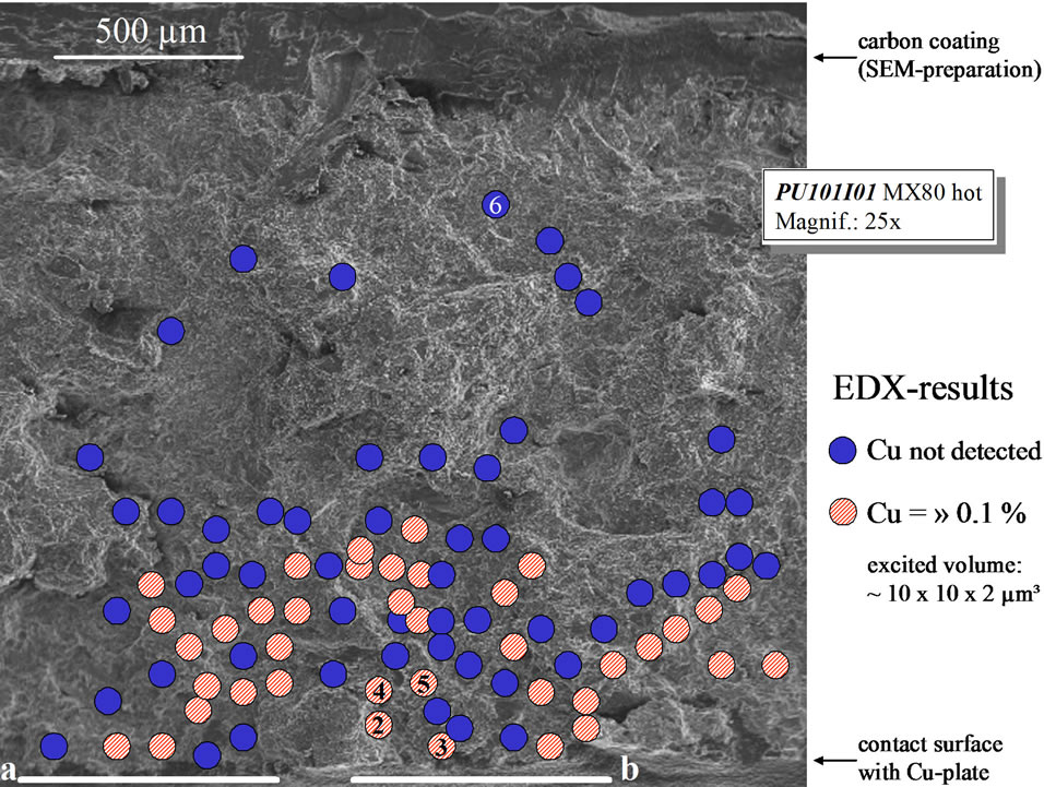
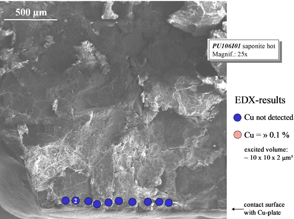
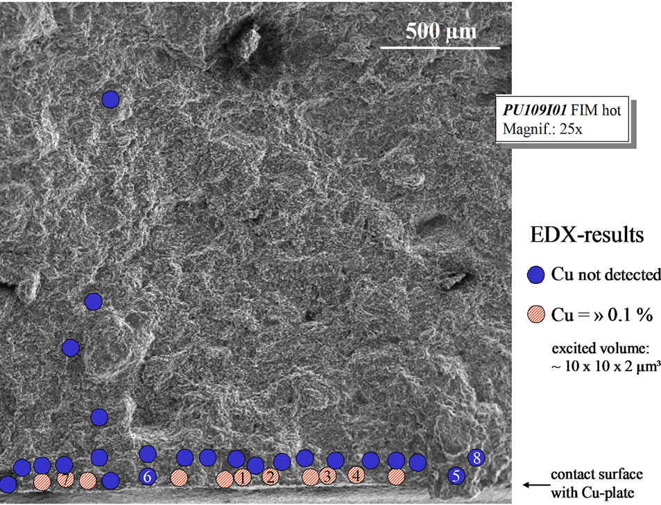
Figure 14. SEM/EDX analysis showing migration of Cu from the hot end of the cells into the respective clay. Upper: Montmorillonite (MX-80) with significant Cu migration. Middle: Saponite with no migration of Cu at all. Lower: Slight, channel-type migration of Cu in mixed-layer clay [3].
and cold parts [3].
The conclusion from this study was that the model of microstructural changes shown in Figure 10 applies to all three clays and that saponite clay sustained the hydrothermal treatment better than the other clays and interacted less with copper metal. This is in agreement with the experience of oil-drilling companies that saponitic drilling muds are more sustainable than those consisting of montmorillonite [12].
The problem is still that the rate of conversion to nonexpandable minerals is not known and that the extent and impact of precipitation of cementing compounds on the buffer clay cannot be quantified with certainty.
The overall conclusion is therefore that the barrier function of buffer clay, even of the most stable type, i.e. the saponite, is questionable in a long term perspective. This leaves us with only one effective barrier to migration of radionuclides, namely the canister of HIPOW type. The buffer is still a necessary component of the defense system because it will reduce groundwater flow around the canisters and support the surrounding rock, preventing rock fall and damage to the canisters. Highquality, smectite-rich buffer clay would not be needed for this but it is still recommended that a clay with saponite as dominant clay mineral and quartz as dominant accessory mineral be used. The major question, largely forgotten by SKB and its sister organizations, is the stiffening of the buffer caused by precipitation of silicious components near the canister. As long as the cementation effect is small the ductility of the buffer clay is preserved and the saponite is the most suitable clay type as demonstrated by the studies referred to. In practice, one may well use commercially available clays containing both saponite and montmorillonite like those in Greece.
4.3. Outline of Nearfield Design of Abandoned Mines Converted to Repositories
Two principles for placing and confining HLW canisters have been suggested by SKB’s sister organizations and they may both form the basis of working out a useful technique for disposal in abandoned mines. One of them was proposed by NAGRA some 15 years ago and the other by ANDRA at about the same time. NAGRA’s concept, shown in Figure 15, implies that the canisters are placed individually on foundations of assembled blocks of highly compacted clay and that the space between the canisters and the rock is filled with blown, very dense granules of smectite clay. The problem with this concept is that the density of the granule fill will be low—about 1800 kg/m3 after water saturation—and that it will be difficult to guarantee homogeneous backfilling, which has to be made remotely.
Figure 16 shows ANDRA’s concept that is similar to the principle for borehole sealing proposed to SKB some 25 years ago [3], implying that large perforated metal tubes are installed and filled with buffer clay embedding
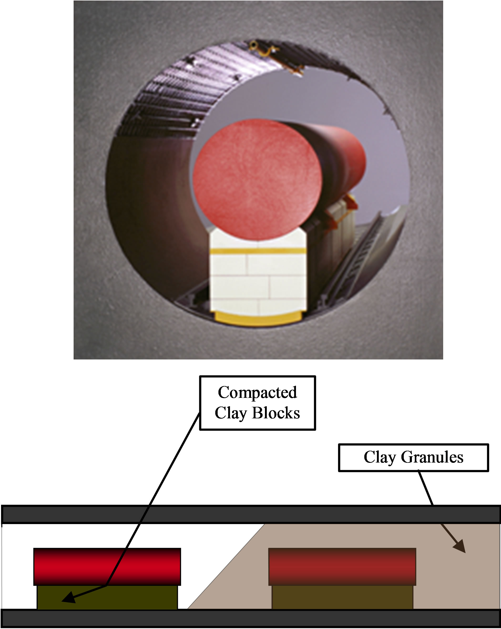
Figure 15. NAGRA’s concept for installation of canisters in a tunnel [1]. The HLW canisters rest on assemblies of dense blocks of expandable clay. The space around the canisters is proposed to be backfilled with blown-in smectite-rich pellets.

Figure 16. Main components of the disposal cell for spent fuel in the French concept. The outer, perforated, tube and the inner tube sleeve are made of carbon steel [1]. The tubes can be many tens of meters long but inflow of water from intersected fracture zones will require construction of bulkheads for isolating them.
an inner sleeve for inserting the canisters [1]. Water will enter through the perforation and saturate the buffer which embeds the inner tube that is only slightly wider than the canisters.
An optimal design principle proposed here is to combine ANDRA’s version with the LRDT principle shown in Figure 11, utilizing also newly developed concrete material for filling the space between the large perforated tube, which is preferably made of Navy Bronze with a high content of copper, and the surrounding rock. The concrete has 10% talc as superplasticizer and a content of 5% - 10% low-pH Merit 5000 cement, which gives a pH of about 10 and a fluidity that is suitable for pumpingit onsite through pipes placed in a shallow groove in the floor while letting air and water out through a pipe at the crown [13]. The sleeve is also made of Navy Bronze for the sake of chemical stability.
While this principle would not be suitable for a new repository in tight rock since the very slow wetting of the buffer would cause desiccation and permanent loss of expandability, it will work well in normally wet deep mines. They should preferably be abandoned copper ore mines for providing a suitable chemical environment. This idea was proposed a number of years ago by German geologists for disposal of low-level radioactive waste in one of the world’s biggest copper mines where mining operations were proposed to continue at one end while waste disposal would run in parallel at the exploited end [14].
4.4. Cost Aspects
Considering first the issue of utilization, i.e. the extent to which repository rock can be utilized for hosting HLW, it is obvious that a repository built for hosting a few thousand canisters is far from cost-effective. Some twenty years ago the estimated cost for construction, design, installations and site investigations was on the order of 6000 MSEK, or about 1500 MUS dollars. Today it would be about 5000 MUS dollars.
Conversion of an abandoned mine will involve only little rock excavation but some preparation in the form of wire sawing for creating plane floors in the drifts and stabilization in the waste placement phase will be needed. The cost for this is very much smaller than for constructing a new repository while maintenance, primarily drainage by pumping in this phase will be costly. Upgrading of elevators, rails, ventilation and illumination will be less expensive than for a new repository while planning of the placement of waste packages and clay isolation based on geohydraulic and rock mechanical analyses will be as comprehensive and expensive as for a new repository. The basis for these analyses, the structural modeling of the host rock, is far less difficult and expensive for converting an abandoned mine where all drifts and rooms are available from start for identifying major discontinuities, than for a new repository. The reliability of the modeling of structure and groundwater movement will be much more adequate than for a new repository for which the early planning of location and orientation of deposition tunnels and holes will be very uncertain because of the very limited structural data. This is because these data come from boreholes with a total volume that is less than 1/10,000,000 of the host rock volume.
The cost for manufacturing canisters of iron/copper is expected to be similar to that of full-copper HIPOW canisters once the technique for the latter has been developed to be on the same level as for the iron/copper canisters. The larger amount of copper for the HIPOW canisters makes the material cost considerably higher, however, and the total cost for constructing a repository by using an abandoned mine may therefore not be very much lower than for a new repository with canisters of iron/copper type.
5. CONCLUSIONS AND DISCUSSION
5.1. Rock Issues
Granitic host rock is excellent for creating a new stable repository for hazardous waste since the strength properties are good but the structural constitution is too complex to be modeled for locating deposition tunnels and holes adequately and for reliable prediction of its hydraulic performance in shortand long-term perspectives. The rock structure cannot be defined with any certainty until the repository is already under construction and the degree of utilization can therefore be low and the construction cost high. Conversion of abandoned mines to repositories means that all essential structural features are known beforehand and that groundwater permeation is largely known from start. Considering cost issues it is obvious that conversion of an abandoned mine to be a HLW repository is much less expensive than to construct a new repository.
5.2. Engineering Barriers
One concludes that the barrier effect of smectitic clay is excellent as long as it has not undergone hydrothermally generated alteration to become stiff and signifcantly more permeable than in unheated form. The longterm isolating effect including the required ductility cannot be proven, which makes it necessary to rely on the integrity of the waste containers. Only the all-copper HIPOW canisters offer safe isolation for 100,000 years. Use of them reduces the need for redundance by rock and buffer to nearly nil. This canister type can be applied to the presently considered repository design as well as to repositories represented by abandoned mines but the difference in cost for creating complete repositories of either type would be dramatic.
Buffer clay containing expandable minerals, smectite or mixed-layer species, is necessary for keeping the groundwater flow through the nearfield of the HLW low and for supporting the rock around the disposal rooms. The hydrothermal conditions for the buffer, with temperatures ranging from initially about 100˚C and ultimately down to ambient rock temperature will cause degradation of the buffer clay. The major part of the content of expandables may be preserved for a considerable period of time but the trend of subsequent conversion to illite is obvious. The hydraulic conductivity will increase and the buffer will undergo stiffening by precipitation of quartz and other silicious matter. This process will cause loss in self-healing potential if the clay is exposed to seismically and tectonically generated strain. The buffer can therefore not be relied on as an effective barrier to migration of released radionuclides but is expected to retain sufficiently much expandability to support the surrounding rock and to keep the groundwater flow rate in the nearfield of the waste reasonably low. The ideal buffer clay would be one with saponite as major smectite component and with a significant content of fine quartz. A most important fact is that the hydraulic gradients acting in rock with HLW repositories will not exceed 1 m/100m (meter pressure difference over 100 m flow length), causing deviation from Darcy’s law and hence lowering the hydraulic conductivity of any dense clay to less than E−9 m/s in a long time perspective, which is acceptable [3].
5.3. Overall Conclusion
The possibility to convert suitable mines to HLW repositories is proposed because of the ease of finding appropriate positions for the waste canisters that have to be all-copper of the HIPOW type since this is the only engineered barrier to release and migration of radionuclides that can be relied on. A practical arrangement for placing the canisters is to use the “borehole sealing technique”, implying installation of large perforated tubes with clay buffer surrounding sleeves into which the canisters are moved. The access to water in abandoned mines guarantees that the required wetting of the buffer can take place undisturbed. Surrounding the perforated tubes with talc concrete provides uniform access to water, suitable pH conditions for avoiding degradation of the contacting buffer, and hindrance of clay particles from the buffer to migrate into the rock.
REFERENCES
- Svemar, C. (2005) Cluster repository project (CROP). Final Report of European Commission Contract FIR1-CT- 2000-2003, Brussels, Belgium.
- SKB (2003) Planning report for the safety assessment SR-Can. SKB, Stockholm.
- Pusch, R. (2008) Geological storage of radioactive waste. Springer-Verlag, Berlin and Heidelberg. doi:10.1007/978-3-540-77333-7
- Pusch, R., Yong, R.N. and Nakano, M. (2011) High-level radioactive waste disposal. WIT Press, Southampton and Boston.
- Popov, V. and Pusch, R. (2006) Disposal of hazardous Waste in underground mines. In: Popov, V. and Pusch, R., Eds., WIT Press, Southampton and Boston.
- Pusch, R. and Weston R. (2012) Impact of scale on rock strength. Proceedings WASET International Conference on Civil and Construction Engineering, 67, 782-788.
- Hökmark, H. (1992) Thermomechanical study of jointed rock around a KBS3-type nuclear waste repository. SKB Int. report AR 92-75.
- Pusch, R. and Yong, R. (2006) Microstructure of smectite clays and engineering performance. Taylor & Francis, London and New York.
- Pusch, R. and Madsen, F.T. (1995) Aspects of the illitization of the Kinnekulle bentonites. Clays and Clay Minerals, 43, 133-140. doi:10.1346/CCMN.1995.0430301
- Nguyen and Thanh, L. (2012) Mineralogical characterization of Fe-driven alteration of smectites. Dissertation, Ernst-Moritz-Arndt-Universität Greifswald, Greifswald.
- Lönnerberg, B., Larker, H. and Ageskog, L. (1983) Encapsulation and handling of spent nuclear fuel for final disposal. SKB/KBS Technical Report 83-20, SKB, Stockholm.
- Gueven, N. and Huang, W.-L. (1990) Effects of Mg2+ and Fe3+ substitutions on the crystallization of discrete illite and illite/smectite mixed layers. International report, Texas Tech University, Exxon Production Research Co., Houston.
- Pusch, R., Warr, L., Grathoff, G., Knutsson, S., Pourbakhtiar, A. and Mohammed, H.M. (2012) Talc-based cement-poor concrete for sealing boreholes in rock. In print.
- Krohne, J. (2006) Report on planned repository for MLW and LLW in coppermine, Kazahkstan. DBETEC, Peine.