Engineering
Vol. 4 No. 10 (2012) , Article ID: 23360 , 4 pages DOI:10.4236/eng.2012.410077
Fabrication of an Fluid Circuit for Equal Filling of a Well Array
Department of Mechanical and Materials Engineering, University of Denver, Denver, USA
Email: Corinne.Lengsfeld@du.edu
Received July 8, 2012; revised August 7, 2012; accepted August 15, 2012
Keywords: Microfluidics; Incubator; Diffusion Bonding
ABSTRACT
Frequently in fluidic circuits there is a need to fill an array of wells. Methods for ensuring equal filling rates have hindered the application of microtechnology to cell culture applications directed to multiwell incubation. The greatest precision of equal fill volume to each well along a row occurred when the channels were extended into the third dimension, whereas, a traditional configuration is planar. This type of configuration utilizes vertical potential energy changes in cooperation with geometric restrictions. This paper presents the 3-D geometry that has five equally spaced wells to sustain equal filling. Moreover the fabrication process used to bond the multi-layer structure into a single 3-D circuit is presented.
1. Introduction
Micro fluidics is the handling and analyzing of small volumes of fluid; it is not necessary that the entire device be miniaturized to be considered a micro device, only that the volume of fluid is on the sub-milliliter scale [1]. Micro fluidic devices have a great advantage over macro scale devices and consequently, they have become great tools for the drug discovery industry and for improving experimentation in the area of biology [2,3]. Advantages of micro analysis systems include: precise micro environmental control [2,4], parallel operation in a single device yielding the ability to perform high throughput analyses [5], reduced sample size thus reducing the amount of chemicals, solvents, cells, and growth media used [3,5-7], and decreased cost of experiments because of smaller fluid volumes [3,5,7]. Lab-on-a-Chip was the first evolution of devices to exploit the advantages of micro fluidics and micro fabrication technology for pathogen cultivation, drug therapy screening, and biological experimentation (including immunoassays, protein analysis, DNA separation and analysis, and polymerase chain reaction) [2,3,6,8].
More recently the development of micro fluidic platforms have been focused towards quite different purposes related to cell and tissue culturing including tissue engineering applications [9], studies in embryonic development [10], yeast and bacterial cell experiments [11]. In these systems the culture of cellular colonies are desirable thus a minimum culture volume near 200 μL is needed.
The specific application for the device presented in this study was involved in the treatment and control of infectious diseases, which calls for the development of a device capable of rapidly, simultaneously, and safely investigate a myriad of culture conditions [11]. Although equal filling issues have not been a problem in single cell situations, with larger bioreactor or incubator systems methods for ensuring equal filling rates have hindered the application of micro-technology to fields like incubator arrays [2,12,13]. Commercial products in the field even suggest “tilting” the array to utilize gravity inequities to solve the problem. This paper presents a 3-D geometry that supplies five equally spaced wells with negligible fluid volume differences. It will also present the diffusion bonding manufacturing technique utilized to build a prototype system and present the experimental results demonstrating the performance.
2. Design and Fabrication
2.1. Equal Filling Fluid Circuit
The design of a fluid circuit which allows fluid injection from one end yet supplies an equal amount of fluid within each individual well distributed along the length of the fluid circuit is not simple. Minor changes in pressure drop from the injection port to each of the well entrances results in unequal volume fluxes. To accomplish equal filling: 1) the pressure drop from the entrance of the parent channel to its terminal end must be substantially lower than the pressure drop along the length of the daughter channels feeding fluid from the parent channel to the well, plus 2) the variation in head loss from injection port through the exit of the daughter channel supplying any well must be minimal. Fluid circuits applied to cellular applications have additional constraints on the minimum channel dimensions (e.g. width and height). Specifically there is a need to avoid uneven filling as a result of channel obstruction, which is frequently dependent on the size of the largest particle in the fluid. For this particular application, the mammalian dry cell diameter ranges between 3 and 9 μm. Thus a minimum channel dimension of 30 times the cell dimension was arbitrarily set. A reduction in fill volume from the desired can result from residual volumes left within the supply channels after injection is complete. To reduce the impact of this problem, all wells are equally spaced along the parent channel and the constraint on the maximum allowable residual was set to 5% (i.e. total channel volume in a single row cannot exceed 5% of an individual well). Finally, the need to create a closed system to eliminate cross contamination requires permanent adhesion of a sterilized cover to the fluid circuit. As a result, a minimum wall thickness of 1 mm was set to ensure structural integrity during diffusion bonding.
A parametric study of fluid circuit designs bounded by the constraints described above with the objective of minimizing the mass flux difference to each of five wells distributed along a single fluid circuit was conducted using computational fluid dynamic simulations. Model validity was checked by comparing the calculated pressure drop using 1-D assumptions based on head loss for simple geometries to those calculated by CFD. These empirical head loss calculations were also used to identify the range of channel dimensions that would be most appropriate to explore. A Navier-Stokes pressure-based solver was utilized to model the inherent low-speed (laminar) incompressible flow. Boundary conditions used in the analysis were: inlet velocity of 1 cm/s, atmospheric pressure at the daughter channel outlets, and a no-slip condition was applied at all wall surfaces. The fluid was assumed to have the properties of water.
Pressure contour plots, Figure 1, show that there is a large pressure drop between the entrance and first daughter channel for the planar configuration compared to the best 3-D geometry explored in this work. Mass flux reports at the exit of each daughter channel, Table 1, confirm what the pressure plot suggests showing 91% of all the mass will distribute to the first well in the planar case. The initial case starting the 3-D channel configuretion study explored the same channel dimensions as the 2-D or planar system, but aligns the daughter tube with gravity and adds a second 90° elbow. This design alteration yields improved pressure drop and mass flux performance, but still preferentially fills first few wells; de-

Figure 1. Pressure (Pa) contours from CFD simulations of: (a) Best 2-D planar geometry and (b) 3-D design with optimal performance. Areas of higher pressure are shown in red and areas of lower pressure are shown in blue.
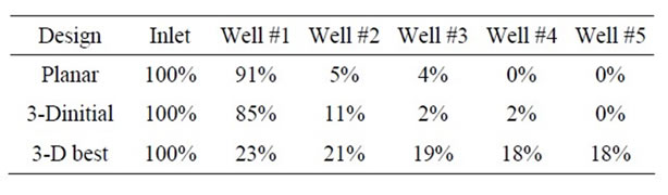
Table 1. Percentage of mass flux entering each well along the fluid circuit for a planar design, 3-D design with similar dimensions to the planar design and a 3-D that met design criteria.
livering only minor amounts to the last wells.
In total twenty-two 3-D design configurations were evaluated. The best 3-D geometry evaluated shows a 5.3% difference in mass flux between the first and last well. This design utilizes square channels where the vertical daughter tube diameter is 27% and the horizontal daughter channel is 33% of parent channel width. The length of each of these segments is 5.5 times the diameter for the vertical channel and 4.5 times the width for the horizontal channel, respectively.
In this investigation, the dimension of the parent channel was constrained by a total circuit volume 5% of an individual well, thus the parent channel dimensions are dependent on the well size. Because other applications likely will explore different well volumes, final dimensions for the best configuration are expressed as a ratio to the parent channel width. It is critical to realize that utilizing these non dimensional geometries for longer designs that supply a larger number of consecutive wells from a single injection port can potentially increase well to well fill volume variation. Locating the injection septum in the center of the feed row permits a total well count in a single row to double. However, similar numerical strategies can provide new geometric dimensions to minimize the problem for even longer rows. For example, the employment of an automated design optimization strategy, such as those described in [14,15], could help reduce this variation even further.
2.2. Diffusion Bonding
The 3-D design developed above necessitates the fabrication of multiple planar channel geometries (6 layers in all) that are subsequently stacked to form the final assembly, Figure 2. Several methods exist to bond multiple layers of a microfluidic circuit. However, the need to limit cross contamination between wells and the environment, as well as, prevent delamination during typical sterilization processes limits the number of assembly strategies. A diffusion bonding technique was selected for these reasons. Functional prototypes were manufactured out of layers of medical grade polycarbonate using micro machining methods. Acetone vapor polishing was employed as the post-processing surface treatment to reduce surface roughness to 0.1 μm.
The exact conditions to diffusion bond six polycarbonate layers sufficiently to withstand autoclaving (>20 minutes time above 121˚C), without inducing alterations to the microchannel cross section requires process optimization as the methods have not been previously published. Appropriate diffusion bonding conditions were found by assessing channel cross sectional shape before and after bonding and sterilization. Standard bulk heating techniques were applied to the entire sample, which brought to approximately 60% of the melt temperature under no load. Next, the sample was compressed under constant pressure prior to cooling. Using Ageorges and Ye [16] as a guide, consolidation pressures from 0.1 to 0.5 MPa were explored. Some variation to cooling time was explored with little effect. The standard operating procedure to provide optimal fusion bonding between the multiple layers of the micro liter array plate is presented in Figure 3 and described below.
Layer Preparation: 24 hours in advance of bonding, all layers are cleaned using ethanol and lint free wipes and placed in a desiccator connected to a vacuum pump capable of operation at elevated temperatures. This desiccation step eliminates solvent remaining within the polymer from forming vapor bubble between layers during bonding as wells as sterilization. The layers are carefully arranged such that all surfaces of each layer had unobstructed exposure to the vacuum. The temperature of the desiccator is set to 50˚C.
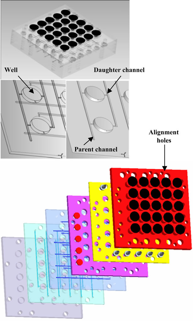
Figure 2. Image of 3-D design (a) Assembled view of six layers; (b) Solid model view of critical channel layer of micro liter array plate; and (c) Exploded view of the six layers.
MTS Preparation: The alignment fixture was set up inside the furnace and is attached to the Material Testing System (MTS). A thermocouple entering through the side of the furnace was place inside a predrilled hole in the fixture to measure the temperature of the fixture. The door was shut and locked while the temperature of the furnace was ramped up to 163˚C.
Consolidation: The layers were removed from the desiccator, placed in the appropriate order, and aligned with stainless steel guide pins that protrude from either side of the pre-assembled layers. The position of the guide pins correspond to predrilled holes in the bottom half of the fixture to aid in placing the layers in the hot furnace and prevent movement under load. The top half of the fixture supplies a normal force of ~44N to the polycarbonate layers. The layers were then heated for 20 minutes at 163˚C. After 20 minutes, the applied force increased at a rate of 89 N/s until it reaches 1.05 kN,
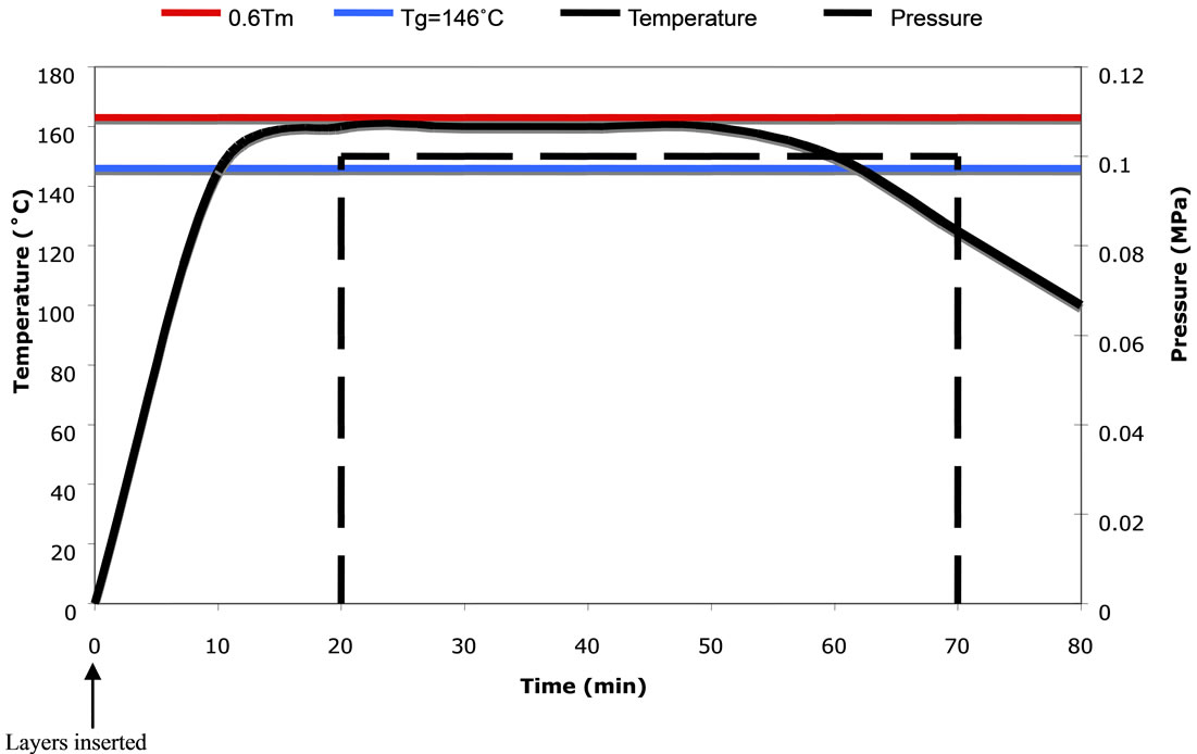
Figure 3. Processing cycle for diffusion bonding of polycarbonate laminate. Operating temperature on the left vertical axis in Celsius, applied pressure on the right vertical axis in MPa.
which is equivalent to the required pressure of 0.1 MPa for the given size. Once the MTS reaches 1.05 kN, the applied load remained constant for 30 minutes to allow the softening of the surfaces and subsequent entanglement of the polymers across the interface.
Cooling: After the 30 minutes of constant pressure and temperature, the furnace was turned off and the door opened. The pressure remained constant for approximately 20 minutes, or until the temperature dropped below the glass transition temperature, TG, of 146˚C. During cooling, the surfaces re-harden and the entangled polymers were now intimately and permanently connected.
Removal: Once cooling was complete, the load was removed.
3. Experimental Apparatus and Procedure
Before Experimental verification of the numerical simulations for equal filling was achieved using a manufactured device described above. A 26-gauge needle was connected to a 3ml syringe and filled with 1.5 ml of 0.4% Trypan Blue Stain in normal saline (0.9% weight/volume NaCl). The syringe was then inserted through the septum of a parent channel that feeds five equally spaced consecutive wells. The plunger of the syringe was slowly, manually depressed until all dye had been ejected from the syringe. The needle was then removed and the procedure repeated for the other four parent channels in the 5 × 5 array. The contents of each well were manually removed using a 1 ml syringe with 26-guage needle. The amount of fluid in each well was subsequently measured by a mass balance in milligrams (e.g. ~300 mg) with sensitivity to a tenth of a milligram. The procedure was repeated for an open and closed system (i.e., gas vents open or closed), as well as, a series of unlevel situations.
4. Results and Discussion
Experimental results from the 2-D planar design shows that the last two wells did not receive liquid, the third cell only receives fluid occasionally, whereas the first well receives 90% of the total liquid injected. The statistical variation in delivered mass to each well from the intended mass is 150.5% based on a 95% confidence interval.
For the best 3-D geometry developed from CFD simulations, experimental results on equal filling shows little dependence on whether the system operates in an open or closed manner, or if injection occurs on a level or tilted surface (<10 degrees). Based on these three experimental conditions the variation in delivered mass to each well from the intended mass is 3.8% based on a 95% confidence interval. The maximum or minimum variation of volume has no correlation to a specific well; moreover the location varies randomly from experiment to experiment. Frequently the entire span of variation is caused by a single well. Because of the random nature of this result, it is hypothesized that slight channel obstruction from particles in the unfiltered fluid solution rather than gravitational or pressure effects drives the variation. As the intended application for this device is disposable, channel fouling from multiple injections would be negligible. It is important to note that the amount of residual liquid in the fluid circuit for the volumes delivered in this study is approximately 2.5% of the mean mass of a single well. However, removal of the entire liquid volume from each well is difficult because of the dimensions and surface tension of water. Therefore, there is a credible argument that the 3.8% variation observed is within experimental sensitivities.
5. Conclusion
The design of a 3-D fluidic circuit design for the equal filling of five equally spaced consecutive wells each with the volume capacity 80 to 300 μl fed by a single parent channel is presented. A square parent channel supplies a vertical daughter tube having a diameter equal to 27% of the parent channel width. This vertical tube connects to another square channel having a width of 33% of the parent channel width. The diffusion bonding methods utilized to bond the polycarbonate layers containing microfluidic channels is described in detail. The process consists of an unloaded 20 minute heating to 163˚C, followed by a 30 minute consolidation at 163˚C and 0.1 MPa. The part is initially cooled for 20 minutes under constant load then allowed to finish cooling under no load. Simulations to assess equal delivery of fluid volume show an approximate 5% variation between the first and last well, while experimental testing found variability to be within 3.8%. Further, experimental testing demonstrates that the circuit is insensitive to operation in a vented vs closed or tilted vs. perpendicular to gravity. Based on extrapolation of the CFD simulations and experimental results, equal filling from the current design could potentially be extended to 8 to 10 consecutive wells. Placing the injection septum in the center of the feed row permits a total well count in a single row to double (i.e., 16 to 20). Therefore, the geometry discussed here should be scalable for dilute aqueous systems to at least a 16 × N array. This would lead to thousands of simultaneous conditions and a significant addition to infectious disease community. Additionally, similar numerical strategies would provide new geometric dimensions that could minimize the problem for even longer rows.
6. Acknowledgements
This work was supported by a grant from the Keck Futures Initiative through the National Academies of Science and Engineering.
REFERENCES
- N. T. Nguyen and S. T. Vereley, “Fundamentals and Applications of Microfluidics,” Microelectromechanical Systems, Artech House, Boston, 2001.
- P. J. Lee, P. J. Hung and L. P. Lee, “Microfluidic Cell Culture Array for On-Chip Cell Biology in Microtechnology,” 3rd IEEE/EMBS Special Topic Conference on Microtechnologies in Medicine and Biology, Oahu, 12-15 May 2005, pp. 382-284.
- P. J. Lee, et al., “Microfluidic System for Automated Cell-Based Assays,” Journal of the Association for Laboratory Automation, Vol. 12, No. 6, 2007, pp. 363-367. doi:10.1016/j.jala.2007.07.001
- S. Cookson, et al., “Monitoring Dynamics of Single-Cell Gene Expression over Multiple Cell Cycles,” Molecular Systems Biology, Vol. 1, 2005, Article ID: 20050024. doi:10.1038/msb4100032
- D. J. Beebe, G. A. Mensing and G. M. Walker, “Physics and Applications of Microfluidics in Biology,” Annual Review of Biomedical Engineering, Vol. 4, 2002, pp. 261- 286. doi:10.1146/annurev.bioeng.4.112601.125916
- J. Pihl, J. Sinclair, M. Karlsson and O. Orwar, “Microfluidics for Cell-Based Assays,” Materials Today, Vol. 8, No. 12, 2005, pp. 46-51.
- S. K. Sia and G. M. Whitesides, “Microfluidic Devices Fabricated in Poly(Dimethylsiloxane) for Biological Studies,” Electrophoresis, Vol. 24, No. 21, 2003, pp. 3563- 3576. doi:10.1002/elps.200305584
- T. Vilkner, D. Janasek and A. Manz, “Micro Total Analysis Systems. Recent Developments,” Analytical Chemistry, Vol. 76, No. 12, 2004, pp. 3373-3386. doi:10.1021/ac040063q
- A. Khademhosseini, et al., “Microscale Technologies for Tissue Engineering and Biology,” Proceedings of the National Academy of Sciences of the United States of America, Vol. 103, No. 8, 2006, pp. 2480-2487. doi:10.1073/pnas.0507681102
- S. Raty, et al., “Embryonic Development in the Mouse Is Enhanced via Microchannel Culture,” Lab on a Chip, Vol. 4, No. 3, 2004, pp. 186-190. doi:10.1039/b316437c
- R. Fulstone, C. M. Coughlan, J. E. Wiktorwicz and C. S. Lengsfeld, “Micro Liter Incubator Array for Understanding Culture Condition Selectivity,” Advances in Bioscience and Biotechnology, Vol. 3, 2012, pp. 87-91.
- L. M. Levine, “Combining Additive and Subtractive Techniques in the Design and Fabrication of Microfluidic Devices,” Nanotech, Vol. 3, 2007, pp. 385-588.
- P. J. Hung, et al., “Continuous Perfusion Microfluidic Cell Culture Array for High-Throughput Cell-Based Assays,” Biotechnology and Bioengineering, Vol. 89, No. 1, 2005, pp. 1-8. doi:10.1002/bit.20289
- M. J. Opgenorth, W. E. McDermott, P. Laz and C. S. Lengsfeld, “A Combined Probabilistic and Optimization Approach for Improved Chemical Mixing Systems Design,” Engineering, Vol. 3, No. 6, 2011, pp. 643-652. doi:10.4236/eng.2011.36077
- M. J. Opgenorth, W. E. McDermott and C. S. Lengsfeld, “Design Process for Coupling Optimization and Probability with Computational Fluid Dynamics,” Atomization and Sprays, Vol. 21, No. 2, 2011, pp. 121-126. doi:10.1615/AtomizSpr.2011002778
- C. Ageorges and Y. Lin, “Fusion Bonding of Polymer Composites: From Basic Mechanisms to Process Optimisation,” Springer-Verlag, London, 2002.