Engineering
Vol. 4 No. 9 (2012) , Article ID: 23213 , 4 pages DOI:10.4236/eng.2012.49066
Model-Based Split-Range Algorithm for the Temperature Control of a Batch Reactor
Department of Process Engineering, University of Pannonia, Veszprém, Hungary
Email: balatonm@fmt.uni-pannon.hu
Received June 28, 2012; revised July 29, 2012; accepted August 10, 2012
Keywords: batch reactor; model-based control; split-range; monofluid thermoblock; temperature control
ABSTRACT
In the manufacturing processes of high value-added products in the pharmaceutical, fine chemical polymer and food industry, insufficient control might produce off-grade products. This can cause significant financial losses, or in the pharmaceutical industry, it can result in an unusable batch. In these industries, batch reactors are commonly used, the control of which is essentially a problem of temperature control. In the industry, an increasing number of heating-cooling systems utilising three different temperature levels can be found, which are advantageous from an economic point of view. However, it makes the control more complicated. This paper presents a split-range designing technique using the model of the controlled system with the aim to design a split-range algorithm more specific to the actual system. The algorithm described provides high control performance when using it with classical PID-based cascade temperature control of jacketed batch reactors; however, it can be used with or as part of other types of controllers, for example, model-based temperature controllers. The algorithm can be used in the case of systems where only two as well as where three temperature levels are used for temperature control. Besides the switching between the modes of operation and calculating the value of the manipulated variable, one of the most important functions of the split-range algorithm is to keep the sign of the gain of the controlled system unchanged. However, with a more system-specific split-range solution, not only can the sign of the gain be kept unchanged, but the gain can also be constant or less dependent on the state of the system. Using this solution, the design of the PID controller becomes simpler and can be implemented in existing systems without serious changes.
1. Introduction
In the pharmaceutical, fine chemical and food industry as well as in several technologies of the polymer industry [1], the high value-added products are manufactured mainly in batch processing units, where the batch or fedbatch reactor is the main unit of the process. Due to the complexity of the reaction mixture and the difficulty of performing online composition measurements, control of the batch reactors is essentially treated as a temperature control problem [2]. The difficulties that arise in the temperature control of batch reactors are mainly caused by the discontinuous nature of operating modes and the multiple operations of the reactors. The controller has to work properly in the case of drastically changing, ramped and constant set-points during the different modes of operation.
The temperature of the reaction mixture is usually controlled by heat exchange through the wall of the reactor with a heat transfer fluid flowing inside the jacket surrounding the reactor. Therefore, the control performance mainly depends on the heating-cooling system associated with the reactor.
Several different configurations of heating-cooling systems are cited in the literature and can be basically separated into two types: multifluid (90% of industrial applications [3]) and monofluid systems [4]. The multifluid systems are widely used in the industry, where water or brine is used for cooling, and steam or hot water for heating purposes. During the temperature control, besides determining the adequate mode of operation and the flow rate of the heat transfer fluid, the changeover of fluid also has to be realised (usually an air purge is applied in the jacket), which results in discontinuities in the operation.
In monofluid systems, single fluid is used to produce different temperature levels by using power heaters, heat exchangers and a refrigerator. Several different configurations are possible depending on the connection method to the jacket and the number of available temperature levels (two or three) [5].
Several different types of jacket configurations can be found in the literature [4] and in the industry that can contain indirect or direct heating/cooling, jacket recirculation loop or direct flow through. The jacket configuration with a jacket recirculation loop and with direct heating/cooling is widely used in the industry both in the case of multiand monofluid systems. Using systems with a jacket recirculation loop is advantageous because a high heat transfer coefficient can be achieved compared to the configuration with direct flow through; local overheating/overcooling can be also avoided and the temperature gradient in the jacket can be reduced.
In this paper, a split-range design technique is described that can be used for either multior monofluid systems with two or three temperature levels. The algorithm contains the model of the actual system. Thus, if it is used on a different system, it can be converted by changing the model. It is basically suitable for the classical PID-based cascade temperature control of jacketed batch reactors; however, it can be used with or as part of other types of controllers, for example, model-based temperature controllers. Besides the switching between the modes of operation and calculating the value of the manipulated variable, one of the most important functions of the split-range algorithm is to keep the sign of the gain of the controlled system unchanged. However, with a more system-specific split-range solution like the one described in this paper, not only can the sign of the gain be kept unchanged, but the gain can also be constant or less dependent on the state of the system. Using this solution, the design of the PID controller becomes simpler and can be implemented in existing systems without serious changes.
2. The Experimental Equipment
In the laboratory of the authors’ department, a batch processing unit (Figure 1) containing a 30-litre reactor with a conventional jacket can be found. The temperature of the reactor can be controlled by feeding heating or cooling fluid into the recirculation loop of the jacket. The monofluid thermoblock contains three similar loops at three different temperature levels and is filled with a mixture of water and ethylene-glycol. The highest (HTL) can be controlled by an electric heater, the medium (MTL) by tap water through a plate heat exchanger, and the lowest (LTL) by a refrigerator. The temperature of the reactor can be manipulated by the coordinated operation of the ball valves connecting the monofluid thermoblock with the jacket recirculation loop (temperature level of monofluid) and the control valve (flow rate of monofluid).
From an economic point of view, it is favourable to apply three different temperature levels, since using a medium temperature level with low energy consumption
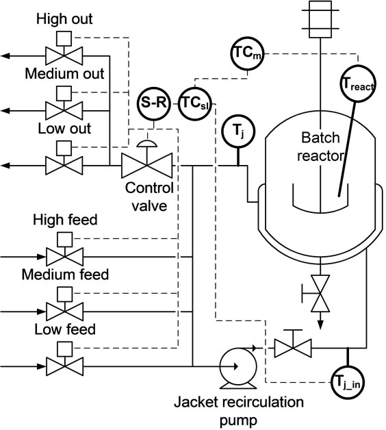
Figure 1. Heating/cooling configuration of the batch reactor.
can reduce the usage of the temperature levels on the boundaries of the temperature range.
3. Jacket Temperature Control of Batch Reactors
In industrial applications, the temperature control of the reactor is usually carried out with PID controllers in a cascade structure [6,7]. Hence, the disturbances affecting the jacket can be eliminated and the constraints regarding the jacket can be defined. The cascade control of the reactor temperature can be seen in Figure 2. According to the authors’ experience, the quality of the slave control loop (jacket temperature control) fundamentally restricts the quality of complex control solutions; hence, the analysis of this loop is the focus of this research.
In the case of the jacket, two measurement points are available: the jacket inlet and outlet temperature. Thus, different possibilities exist for choosing the controlled variable: the jacket inlet, jacket outlet and their average temperature. The best choice for the controlled variable of the jacket temperature control is the jacket inlet temperature because it results in simpler dynamics and constraints related to the jacket can be simply handled. This configuration can be seen in Figure 1.
In industrial control engineering, a split-range controller is preferred in the slave loop of the cascade control to operate two actuators with different effects at the same time. Mostly proportional splitting is used in the case of two modes of operation [8]. In terms of the PID controller, the two actuators can be considered one manipulated variable and the split-range algorithm as part of the controlled system. The main role of the split-range algorithm is to ensure the sign of the gain of the controlled object remains unchanged. For this purpose, the split-range algorithm in Figure 3 is the simplest and most widely used solution in the industry.
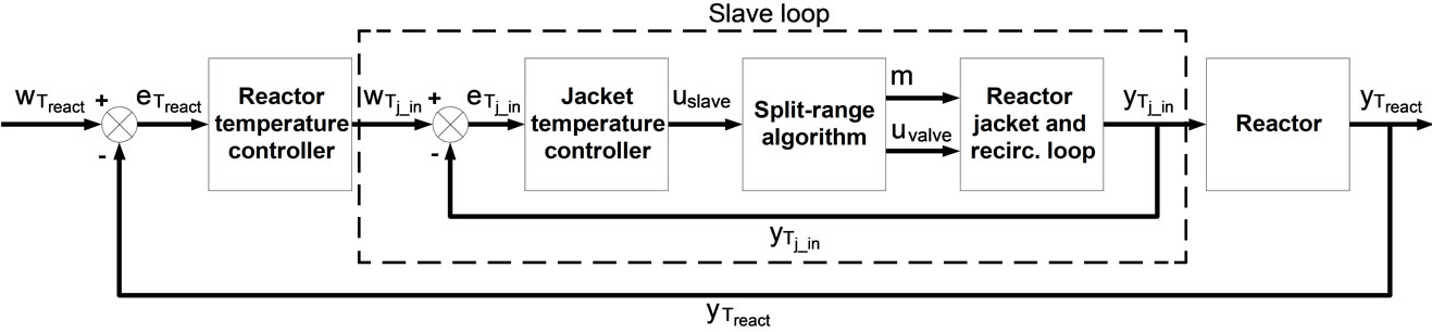
Figure 2. Cascade control of the reactor temperature.

Figure 3. Split-range algorithm for two modes of operation.
Using three different temperature levels as modes of operation, the control becomes more complicated; keeping the sign of the gain of the controlled object unchanged is not as trivial as in the case of two modes of operation. However, due to the aforementioned advantages of systems with three different temperature levels, the research efforts on controllers handling such systems are becoming more important. In the literature, only a few papers can be found that deal with controllers used in systems with three different modes of operation, and most of them present advanced control solutions such as model predictive control [5,9]. The aim of this study is to find a solution that uses the model of the controlled object and can be implemented in the conventional cascade temperature control structure of batch reactors (using PID controllers) without restructuring or using advanced control solutions. Thus, this paper will describe a modelbased split-range solution handling three temperature levels in the case of a monofluid thermoblock and a jacketed batch reactor with a recirculation loop.
4. The Model-Based Split-Range Algorithm
The aim of this study was to develop a split-range algorithm more specific to the jacket configuration commonly used in the industry, which provides better control performance compared to other more universal solutions.
From a modelling point of view, the jacket recirculation loop can be separated into the jacket of the reactor and a mixer, as seen in Figure 4. If the temperature change of the jacket inlet caused by the reactor differs significantly from the temperature change caused by the

Figure 4. Structure of the jacket recirculation loop.
thermal fluid feed, which is mainly relevant in the case of systems located in the industry but not valid for smallscale laboratory reactors, then the jacket recirculation loop can be satisfactorily described with a mixer model (M1). In this case, the reactor is treated as an unmeasured load disturbance. If the dynamics of the two effects are commensurable, then the model can be extended with the model of the jacket (M2) that contains the temperature of the reactor. In this case, the temperature of the reactor is treated as a measured disturbance.
4.1. Modelling Consideration: Mixer Model Only (M1)
The steady-state model of the mixer can be seen in the following equation:
 (1)
(1)
 (2)
(2)
Considering the aforementioned model, the gain of this object (slave loop object) can be evaluated from Equation (2), where the valve is taken into account with linear characteristics (as it is in the physical system).
 (3)
(3)
The resulting gain values in the case of all three modes of operation depending on the jacket temperature can be seen in Figure 5. The gain varies depending on the jacket outlet temperature in all three modes of operation, and the gain changes sign at different temperature values. Only highly exothermic/endothermic reactions can cause the jacket temperature (through the wall of the reactor) to

Figure 5. The gain of the slave loop object in case of M1.
be higher/lower than the available highest heating/lowest cooling media. Thus, the reactor operates in most of the operation time between the available highest and lowest temperature levels. However, when using three modes of operation in the case of the medium temperature level, the sign of the gain can change during normal operation, as can be seen in Figure 5. Thus, it has to be considered in the split-range algorithm.
4.2. Modelling Consideration: Mixer and Jacket Model (M2)
The model of the slave loop object can be described with the following two equations if the dynamics of the heat transfer between the jacket and the reactor is comparable with the dynamics of the temperature change caused by the convectional heat flow of the thermal fluid entering the jacket recirculation loop from the monofluid thermoblock.
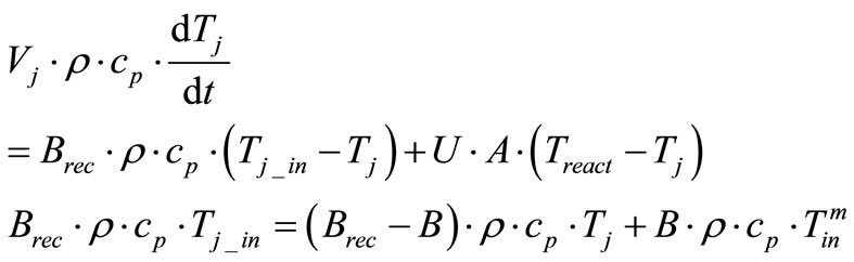 (4)
(4)
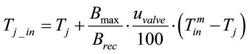
In a steady state, the jacket inlet temperature can be derived from the previous equations as follows:
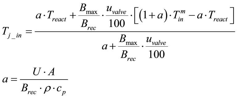 (5)
(5)
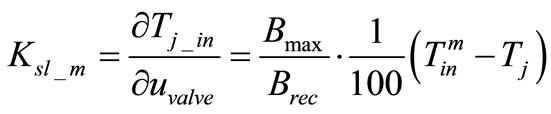
The gain of the resulting object can be calculated by the following equation where the gain is a function of the valve opening, the temperature of the reactor, and the actual jacket recirculation loop inlet temperature.
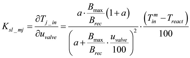 (6)
(6)
The gain values of the object containing the mixer and the jacket model can be seen in Figure 6. In all three modes of operation, the values of the gain as well as the sign changes in the function of both the reactor temperature and the valve opening.
4.3. The Split-Range Algorithm
From the aspect of the slave loop controller, the splitrange algorithm can be considered part of the controlled object, which has the role of keeping the sign of the gain of the controlled object unchanged and managing the two manipulated variables (mode of operation and the control valve) of the slave loop object [9]. In addition to this role, an adequate split-range algorithm can also compensate for the varying of the gain both in the case of jacket temperature and a change in the mode of operation.
In the first step of the algorithm, the maximal possible steady-state jacket inlet temperatures at maximal control valve opening are calculated at all three temperature levels. The two modelling considerations result in different equations. According to the M1 modelling consideration, the jacket inlet temperatures at maximal valve opening can be calculated by the equation on the left in Table 1; when the model of the jacket is also taken into account (M2), the jacket inlet temperatures can be calculated by the equation on the right.
The output of the slave loop PID controller is converted to temperature range according to Equation (7). With this conversion, the output of the PID controller can be handled as a desired steady-state temperature for the jacket inlet temperature.
 (7)
(7)
The minimal and maximal possible steady-state jacket inlet temperatures (Table 2) are derived from the previously calculated  (Table 1) and the actual jacket temperature.
When choosing the adequate mode of operation, the possible steady-state jacket inlet temperatures are first arranged in ascending order. These values can be seen in Table 4.
Using the previously created  vector, the adequate mode of operation can be chosen in the function of the temperature range controller output. The different cases can be seen in Table 3.
The valve opening can be calculated from the steadystate model of the slave loop object (Equation (1) or (4)).
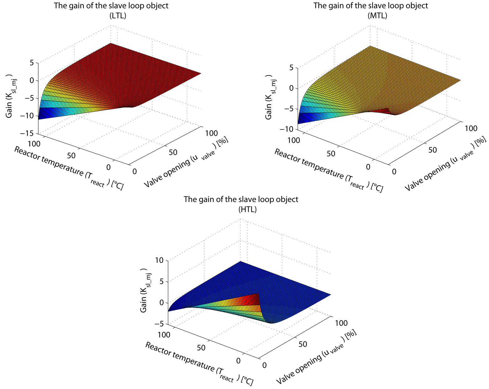
Figure 6. The gain of the slave loop object in case of M2.
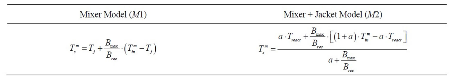
Table 1. The steady-state jacket inlet temperatures at maximal valve opening.
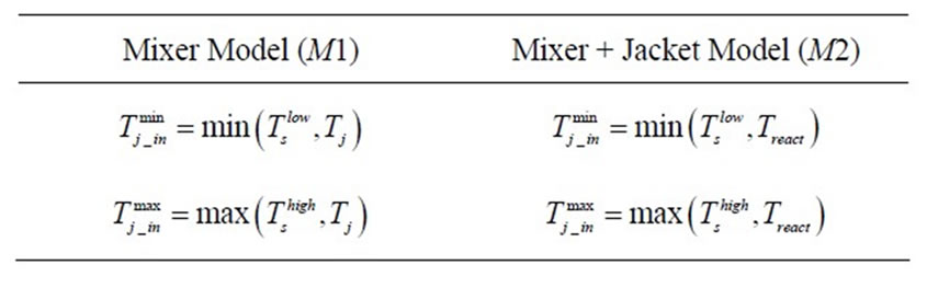
Table 2. The minimal and maximal possible steady-state jacket inlet temperatures.
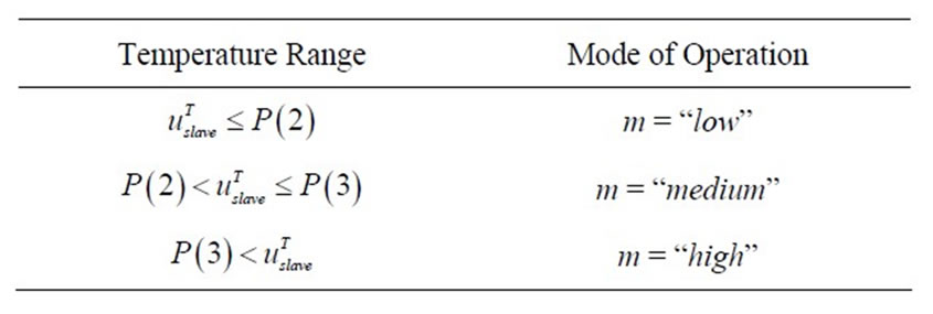
Table 3. Choosing the adequate mode of operation.
The two modelling considerations result in different equations for the calculation of the valve opening, which can be seen in Table 5.
The previously described split-range algorithm can result in several different split-range characteristics that are dependent on the actual temperature of the jacket or the reactor (depending on the type of model) and the temperature levels of the monofluid thermoblock. In the case of the modelling consideration M1, some example characteristics at different jacket temperatures can be seen in Figure 7. For example, at 50˚C according to Equation (7), the PID output percentage where the medium and high temperature levels have zero valve opening represent the jacket temperature on the basis of the PID output. The heating/cooling capacities are also continuous when more than one heating/cooling media is
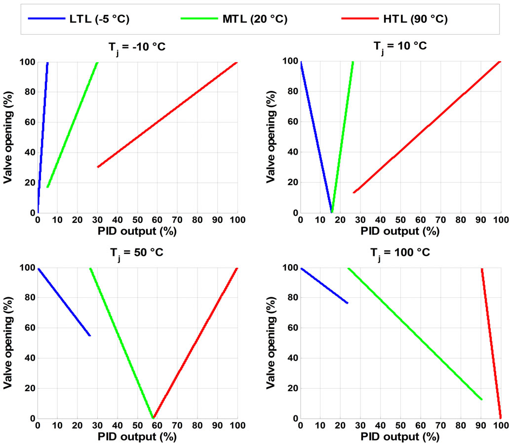
Figure 7. Example of split-range characteristics at different jacket temperature values in the case of M1.

Table 4. Ordering the possible steady-state temperatures in different cases.

Table 5. Calculating the valve position.
available.
Some resulting characteristics can be seen in Figure 8 in the case of the modelling consideration M2. These characteristics are similar to the ones in Figure 7; the differences arise only from differences of the models.
4.4. Gain of the Virtual Object
If the split-range algorithm is considered part of the controlled object, the gain of this virtual object can be calculated with the same equation (Equation (8)) in the case of both modelling considerations. However, the gain values of the virtual objects differ because  and
and  depend on the temperature of the jacket or the reactor.
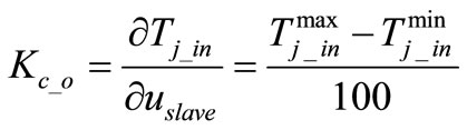 (8)
(8)
With this split-range algorithm, it is possible to conclude that the sign of the gain does not change in the whole operation range. Moreover, the gain is kept constant in the normal operation temperature range and is also independent of the actual mode of operation. Therefore, as an outcome, the change in the mode of operation does not result in a drastic change in the output of the
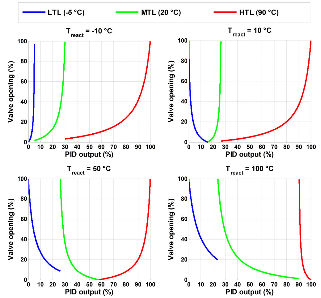
Figure 8. Example of split-range characteristics at different jacket temperature values in the case of M2.
PID controller. The gain values in the case of M1 can be seen in Figure 9.
In the case of M2, the resulting gain values can be seen in Figure 10.
Using the previously described split-range algorithm, the varying of the gain of the slave loop object, which is a function of several variables, can be compensated. The only dependency left in the gain of the virtual object is the varying temperatures of the monofluid thermoblock loops; however, this can be compensated with the PID controller.
5. Results
Before testing the split-range algorithm on the pilot plant simulation, tests were carried out in order to ascertain the proper operation of the split-range algorithm and determine the parameters of the slave loop PID controller. For the slave loop controller, a constrained PI controller was chosen [10].
5.1. Simulation Results
The parameters of the slave loop PID controller were identified by numerical optimisation. The set-point profile was composed to contain drastic changes, constant and ramped set-point ranges in the operating range of the reactor, with the aim to analyse the behaviour of the two model-based split-range solutions. In the reactor, a constant heat flow was introduced to simulate a fictional chemical reaction. In the case of the M2-based split
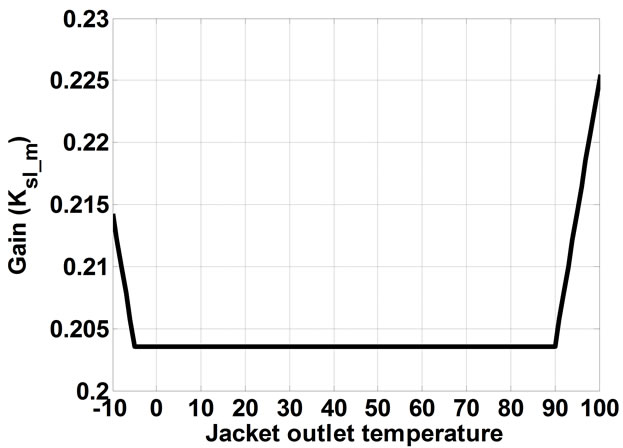
Figure 9. The gain of the virtual object in the case of M1.
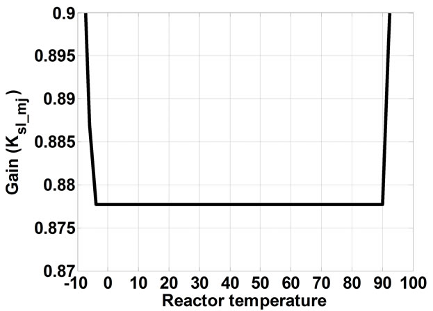
Figure 10. The gain of the virtual object in the case of M2.
range solution, the simulation results can be seen in Figure 11. The behaviour of the PID output is relatively fluctuating, which is a disadvantageous property of this solution. The parameters used in the model of this split-range solution were exactly the same as used in the
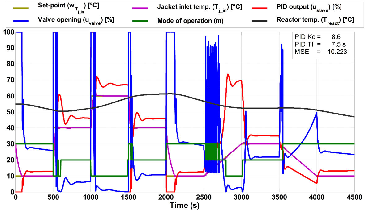
Figure 11. Simulation results in the case of the M2-based split-range algorithm.
simulation model. Thus, the modelling error was eliminated. The oscillation effect from 2500 seconds is caused by the inadequate sign of the gain used by the split-range algorithm; however, in a system where the dynamics of the jacket and the recirculation loop is similar (for example, in small-scale laboratory reactors), this effect does not occur.
The PID parameters identified by numerical optimisation significantly differed for the two split-range solutions, which can be unequivocally explained by the different gain values of the virtual objects.
The simulation results in the case of the M1-based split-range solution can be seen in Figure 12. With this solution, better results can be achieved, and no oscillation or fluctuation is experienced. Besides identifying the parameters of the PID controller for this virtual object by numerical optimisation, satisfactory parameters can also be determined by trial and error. This can promote the use of this solution in industrial applications where control engineers have significant PID controller tuning experience.
According to the experience in simulation tests, the M1-based split-range solution appeared to be the better modelling approach. It is more robust than the solution containing the M2 model, which results in the slave loop being less sensitive to the PID parameters. However, the main advantage of the M1-based split-range solution is the simplicity of the model. It only contains such parameters that can be measured easily in the real system (for example: flow rate, temperature); there is no need to identify the heat transfer coefficient, heat transfer area, etc. of the reactor. Thus, it is not as sensitive to modelling error and is more suitable for different kinds of jacket configurations. Due to its simplicity, it can be easily implemented in industrial controllers without serious changes to the configuration.
5.2. Test Measurement Results
After choosing the proper modelling solution by simulation, the resulting split-range algorithm was tested on the pilot plant. The results of the test measurement can be seen in Figure 13. During the test measurements, similar to the simulation, constant reaction heat was introduced to the reactor with a special loop design for the physical simulation of chemical reactions [11]. The most notable differences between the simulation and test measurement result are caused by the varying temperatures of the monofluid loops of the thermoblock, which remained constant during the simulation. The oscillation between 500 and 1000 seconds, where a near-zero valve opening would be needed, can be explained with the construction of the system and the lag of the control valve in that region.
6. Conclusions
In the case of batch reactors, the most important controlled variable is temperature, since in the manufacturing processes of high value-added products in the pharmaceutical, fine chemical polymer and food industry, insufficient control might produce off-grade products. This can cause significant financial losses, or in the pharmaceutical industry, it can result in unusable batches. Thus, the temperature control of batch reactors is an important area of research. In the industry, an increasing number of heating-cooling systems utilising three different temperature levels can be found. Although they are advantageous from an economic point of view, they make the control more complicated.
The authors have developed a split-range algorithm that is more system-specific. However, it can be implemented in the classical PID-based cascade temperature control of batch reactors without any serious changes.
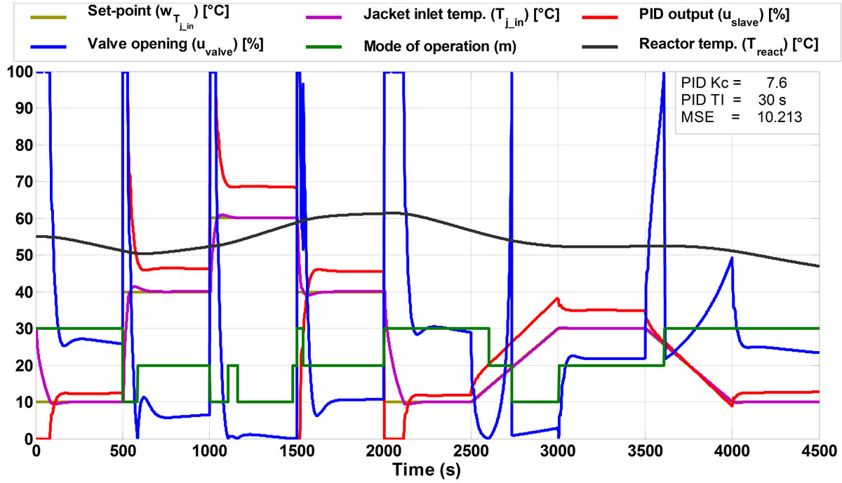
Figure 12. Simulation results in the case of the M1-based split-range algorithm.

Figure 13. Test measurement results in the case of the M1-based split-range algorithm.
For this purpose, a split-range designing technique was developed. In this split-range solution, not only is an algorithm described but a way of thinking is also presented where the model of the jacket recirculation loop is used for control purposes in the split-range algorithm. A similar way of thinking can be used in the case of other jacket configurations. By using the described split-range algorithm, not only can the varying sign of the gain of the slave loop object be compensated but also the varying of the gain caused by the multiple dependencies. The gain of the resulting virtual object that contains the slave loop object and the split-range algorithm is only the function of the temperature values of the monofluid thermoblock loops, which can be compensated with the PID controller.
This paper describes two modelling considerations for a specific jacket configuration that is common in the industry. One of the two modelling approaches contained only a mixer model for describing the jacket recirculation loop (M1), and in the other approach, the model of the jacket was also considered (M2) in addition to the mixer. From the simulation results, the first modelling consideration (M1) proved to be the better choice, as it is not sensitive to the model parameters, provides smoother manipulation compared with the other solution, a wider range of PID parameters can be used for satisfactory control performance, and the equations used are simpler. It only contains such parameters that can be measured easily in the real system (for example: flow rate, temperature); there is no need to identify the heat transfer coefficient, heat transfer area, etc. of the reactor.
The resulting model-based split-range solutions were analysed with simulation and also tested on the pilot plant. The PID parameters were identified by numerical optimisation. Good control performance was achieved using the split-range algorithm containing only the mixer model. Hence, this modelling consideration is more favourable.
7. Acknowledgements
This work has been supported in part by the European Social Fund in the frame of the TAMOP-4.2.2/B-10/1- 2010-0025 and the TAMOP-4.2.1/B-09/1/KONV-2010- 0003 projects.
REFERENCES
- S. Erdoğan, M. Alpbaz and A. R. Karagöz, “The Effect of Operational Conditions on the Performance of Batch Polymerization Reactor Control,” Chemical Engineering Journal, Vol. 86, No. 3, 2002, pp. 259-268. doi:10.1016/S1385-8947(01)00183-8
- M. Friedrich and R. Perne, “Design and Control of Batch Reactors—An Industrial Viewpoint,” Computers & Chemical Engineering, Vol. 19, 1995, pp. S357-S368. doi:10.1016/0098-1354(95)00042-Z
- Z. Louleh, M. Cabassud and M. V. Le Lann, “A New Strategy for Temperature Control of Batch Reactors: Experimental Application,” Chemical Engineering Journal, Vol. 75, No. 1, 1999, pp. 11-20. doi:10.1016/S1385-8947(99)00073-X
- J. E. Edwards, “Dynamic Modelling of Batch Reactors & Batch Distillation,” Paper Presented at the Batch Reactor Systems Technology Symposium, Teesside, 2001. http://www.chemstations.com/content/documents/Technical_Articles/jeedyna.pdf
- H. Bouhenchir, M. Cabassud and M. V. Le Lann, “Predictive Functional Control for the Temperature Control of a Chemical Batch Reactor,” Computers & Chemical Engineering, Vol. 30, No. 6-7, 2006, pp. 1141-1154. doi:10.1016/j.compchemeng.2006.02.014
- D. Vasanthi, B. Pranavamoorthy and N. Pappa, “Design of a Self-Tuning Regulator for Temperature Control of a Polymerization Reactor,” ISA Transactions, Vol. 51, No. 1, 2012, pp. 22-29. doi:10.1016/j.isatra.2011.07.009
- Control Station Inc., “A Cascade Control Architecture for the Jacketed Stirred Reactor,” 2012. http://www.controlstation.com/page/187-a-cascade-control-architecture-for-the-jacketed-stirred-reactor
- B. W. Bequette, S. Holihan and S. Bacher, “Automation and Control No.s in the Design of a Pharmaceutical Pilot Plant,” Control Engineering Practice, Vol. 12, No. 7, 2004, pp. 901-908. doi:10.1016/j.conengprac.2004.01.002
- J. Madár, F. Szeifert, L. Nagy, T. Chován and J. Abonyi, “Tendency Model-Based Improvement of the Slave Loop in Cascade Temperature Control of Batch Process Units,” Computers & Chemical Engineering, Vol. 28, No. 5, 2004, pp. 737-744. doi:10.1016/j.compchemeng.2004.02.027
- F. Szeifert, L. Nagy, T. Chován and J. Abonyi, “Constrained PI(D) Algorithms (C-PID),” Hungarian Journal of Industrial Chemistry, Vol. 33, No. 1-2, 2005, pp. 81- 88.
- M. G. Balaton, L. R. Toth, L. Nagy and F. Szeifert, “Reaction Heat Flow Control by Dynamically Calibrated Thermometers,” Proceedings of the 11th International PhD Workshop on Systems and Control, Veszprém, 1-3 September 2010, pp. 80-85.
Nomenclature
 Heat transfer area between the jacket and the reactor (m2)
 Constant
 Actual flow rate of the feed into the jacket recirculation loop (m3/h)
 Maximal flow rate of the feed into the jacket recirculation loop (m3/h)
 Flow rate in the jacket recirculation loop (m3/h)
 Specific heat of the thermal fluid (kJ/kgK)
 Control error of the slave loop
 Control error of the master loop
 High temperature level
 Gain of the virtual object in the case of the mixer model
 Gain of the virtual object in the case of the mixer + jacket model
 Gain of the slave loop object in the case of the mixer model
 Gain of the slave loop object in the case of the mixer + jacket model
 Low temperature level
 Mode of operation {low, medium, high}
 The model containing the mixer model
 The model containing the mixer and jacket model
 Medium temperature level
 The possible steady-state jacket inlet temperatures arranged in ascending order (1 × 4 vector)
 Temperature of the high temperature level (monofluid thermoblock) (˚C)
 Temperature of the low temperature level (monofluid thermoblock) (˚C)
 Temperature of the feed stream entering the recirculation loop (˚C)
 Temperature of the medium temperature level (monofluid thermoblock) (˚C)
 Jacket outlet temperature (˚C)
 Jacket inlet temperature (˚C)
 Maximal possible steady-state jacket inlet temperature (˚C)
 Minimal possible steady-state jacket inlet temperature (˚C)
 Steady-state jacket inlet temperature at maximal valve opening (high temperature level) (˚C)
 Steady-state jacket inlet temperature at maximal valve opening (medium temperature level) (˚C)
 Steady-state jacket inlet temperature at maximal valve opening (low temperature level) (˚C)
 Steady-state jacket inlet temperature at maximal valve opening (˚C)
 Heat transfer coefficient (kW/m2K)
 Temperature range PID controller output in the cascade controller loop (˚C)
 PID controller output in the cascade controller loop (%)
 Valve opening (%)
 Volume of the jacket (m3)
 Set-point of the slave controller (˚C)
 Set-point of the master controller (˚C)
 Controlled variable of the slave loop (˚C)
 Controlled variable of the master loop (˚C)
Greek letters
 Density of the thermal fluid (kg/m3)