Engineering
Vol. 3 No. 9 (2011) , Article ID: 7326 , 10 pages DOI:10.4236/eng.2011.39107
Rehabilitation of an Existing Office Block
The Institute of Structural Engineering, Poznan University of Technology Poland, Poznan, Poland
E-mail: tomasz.blaszczynski@opal.info.pl, jacek.wdowicki@put.poznan.pl
Received February 1, 2011; revised August 4, 2011; accepted August 20, 2011
Keywords: Column-Slab System, Prefabricated Structure, Rehabilitation, Static and Dynamic Analysis
ABSTRACT
A new owner wishes to refurbish the analysed building assembled in 70’s to modern intelligent office block and to develop up to 3000 m2 of a new part. The old office building has been in use until late 80’s. First two floors are made as a monolithic and the rest are prefabricated as RC frame with the shear walls in both directions. All aspects, which came from the coexistence of an old and new part of the office block, will be the scope of an article. The BW for Windows program has been used for computations. In our paper models of shear wall structures in the modernised part as well as the new adjacent part have been shown. The short period of time necessary to obtain the results of the analysis has allowed for a fully interactive structural design. Many analyses have been created to estimate structural space stiffness for existing and new part of the building. Analysis showed, that existing part deflections were 7 times less then permissible one and after concrete grade of a new part has been changed, deflections for both parts were almost the same.
1. Introduction
The building under investigation is an example of a structure with many prefabricated elements. It was designed and constructed in its original shape around 1975 as an office building for one of the biggest electrical companies, and after the owner’s change it had to be revitalized to the state of a new generation building. The revitalized building under investigation was a 12-storey building, with dimensions 31.9 m × 13.4 m, shown in Figure 1. The load bearing superstructure of the building was a three-nave transverse RC frame. The analysed building was founded on a monolithic, beam and slab raft. The slab thickness was 0.6 m, and the beam dimensions were as follows: height –1.4 m, width –2.0 m. The beams were placed in both directions in the axes of columns of the monolithic-prefabricated superstructure frame and in the axes of shear walls. Up to +8.10 m level (2 storeys) it was constructed as a monolithic one and above this level as a three-nave prefabricated post and beam frame. The posts schedule is 4.8 + 3.0 + 4.8 m in 6.0 m spacing.
The building stiffness was provided by a monolithic reinforced concrete shear walls system of 0.3 m thickness, joined horizontally by existing prefabricated floors. The walls were constructed as monolithic filling of the frame system and as independent gable and longitudinal walls. In all storeys prefabricated floors made of reinforced hollow panels dominated. On the base of hollow panel floors a ventilated dual flat roof was built, but it

Figure 1. The building before revitalization
was not actually ventilated. During macroscopic tests a few cracks in structural frames and shear walls were detected. The construction elements strength state was assessed on the base of non-destructive sclerometric tests of the concrete. They showed the lowest strength of the monolithic elements on I, II, V, VIII, X and XI storey, which could have compression strength of 11 to 19 MPa in 28 days after construction. The rest of elements showed strength of 20 to 39 MPa, but after years the concrete matured to such an extent, that in the weakest elements had strength of 21 MPa, which resulted in classification sufficient for future correct work of the structure. The analysis of current technical state of the supporting structure of the existing part of the analysed office building in Poznan showed its full ability for typical office functions.
The main aim of the building revitalization was constructing an additional part of it. This part was to contain well-lit office open space. This job created a challenge for the structural engineers and resulted in some difficulties during structural designing. It was also necessary to design the new part of the building in such a way, so it would not affect unfavourably the existing part of the building. Due to these factors, the newly designed part contained a structural system consisting of two parts, divided by a structural movement joint of the revitalized existing and newly built parts (Figure 2).
The newly built part was designed as a 14-storey building, containing a basement. Due to the height of the existing part, and, what follows, the need of small structural thickness, a solution was a post-slab structure in three-nave system, on punching shear reinforcement base. The slabs were designed as RC monolithic ones, of Filigran type, the thickness of which differed from 0.20 to 0.25 m, made from grade C30/37 concrete (according to [1]). The slabs work in multi-span system, as 2-way, dot supported on RC columns. This part was also founded on a monolithic, beam and slab raft. As the new part was provided with a basement, it resulted in two different foundation levels.
The basic structural changes in the existing building
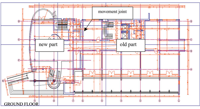
Figure 2. The building layout after rehabilitation.
demanded making large holes in the longitude shear walls and in the transverse shear wall near the elevator shaft. During the modernization the gable evacuation staircase was eliminated, designing an interfloor slab in this space. Additionally, a sloping glass wall on the base of an individual steel structure on the ground level and first floors, was designed. Due to lack of structural walls in the new part of the building, a system of shear walls was designed. It consisted of two transverse reinforced concrete walls (thickness 0.30 m), one of which was curved, and four short longitude walls, forming a social zone between the existing and designed part. In the structural system the following acceptable values of horizontal displacement [2] were assumed:
• for the existing part f = 42.9/1000 = 0.0429 m = 42.9 mm,
• for the new part f = 48.6/1000 = 0.0486 m = 48.6 mm.
2. Applied Analytical Model
The static analyses was carried out by the continuous model [3,4]. A single wall or a group of walls joined in a monolithic way creates a 3-D shear wall (Figure 3). The structure may consist of an unlimited number of two and three-dimensional shear walls freely distributed in a plan. The same height shear walls are considered. They may be joined by lintel's bands or by flexible joints. The structural properties of shear walls, lintels and vertical

Figure 3. 3-D shear wall structure: 1- 3-D shear wall, 2- continuous con-nection, 3- floor.
joints are uniform along the building height. A diaphragm action of all floors is taken into consideration as the effect of its in-plane infinite rigidity and negligible transverse one. The height to width ratio of the shear walls is such that each wall may be treated as an open thin-walled beam. Some difficulties concerning a great number of unknowns and ill-conditioning of a problem for slender structures, which appear in the discrete model, may be avoided in a simple way using the continuous model.
For the dynamic analysis of shear wall tall buildings a continuous-discrete approach was used [4,5]. In this approach the structure mass matrix is found with the lumped mass assumption. To find the flexibility matrix each lumped mass is loaded subsequently with a unit horizontal generalized force and the corresponding horizontal displacement vector to the whole structure is found by the continuous connection method.
3. Integrated System for Analysis
The system considers lateral and vertical loads, free located in plan and freely distributed along the height. It is user-oriented and not expensive in operation [5]. Dynamic computations determine the displacement of the vibrating structure in relation to the static equilibrium. Therefore, the total displacements of a building are algebraic sum of displacements generated by static loads and displacements computed by means of a dynamic analysis. It is difficult to predict which displacement values, produced by pressure wind or an earthquake, will be larger in the zones characterized by a moderate degree of seismicity (rather small ones). Consequently, which one should be added to the displacements caused by dead and live loads to obtain extreme values of the displacements. The fact that the direction of a seismic wave is unknown creates additional difficulty. Thus, it is necessary to compute a dynamic response of the structure at different seismic wave directions, particularly, in the case of buildings without characteristic stiffness axes. Similar difficulties can come across when computing forces in connecting beams and stresses in the walls.
Without a computer program calculating extreme values of: displacement, shear forces in connecting beams and numerous stresses in the walls on the basis of the previously computed values for the load cases, calculations can be time-consuming and it is very easy to make a mistake in this laborious task. The difficulties described above do not occur when the integrated system is used. The integrated system presented in the paper is created by connecting two subsystems: one for static analysis (SAMB) and the other one for a dynamic analysis (DAMB). The modules of interface, necessary for integration, do not exceed 5% of total size of the system. Apart from that only minimal changes in the existing programs are required.
The shear walls can have any cross-sectional shape and their location and orientation can be freely distributed in the plan. Lateral loads are described by loads qx(z), qy(z), ms(z) for characteristic ordinates, and values of concentrated points loads at any storey. The building can be affected by horizontal seismic waves of any direction.
The input data in a form similar to the problem-oriented language are given. They are grouped in the following way:
• job information,
• basic data (e.g. modules of elasticity, properties of material etc.),
• coordinates of characteristic points in the chosen global coordinates OXYZ,
• properties of shear walls, vertical bands and flexible joints,
• properties of floor slabs,
• specification of each storey (bottom and top distance from the base and floor, slab type number),
• declaration of the design response spectrum,
• declaration of the directions of seismic waves,
• specification of the static load and settlement cases,
• control variables.
The correctness of input data is checked in the system.
The system output is presented in tables as well as in graphs and includes the following results:
• geometrical characteristics of shear wall cross-sections,
• mass characteristics of all storeys,
• eigenfrequencies and mode shapes,
• displacements,
• shear forces and bending moments in connecting beams,
• normal, shear and principal stresses in the characteristic points of a floor plan at any level,
• optional internal forces in shear walls.
The results are computed for any ordinates. All results can be obtained for each loadcase and any required combination or envelope.
The Integrated System for static and dynamic analysis of multistorey buildings is composed of twenty four modules of the first level in the form of units compiled independently. The individual units of the Integrated System communicate among themselves by means of one disk file.
3.1. Static Analysis
The first subsystem is for static analysis of multistorey buildings (SAMB—Static Analysis of Multistorey Buildings) [6]. The static analysis has been performed using as unknowns intensity functions of shear forces in continuous connections. In this formulation governing differential equations are as follows:
 (1)
(1)
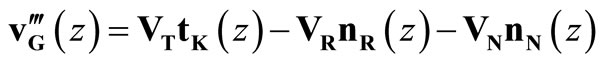 (2)
(2)
The boundary conditions for (1) and (2) can be stated as follows:
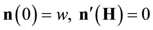 (3)
(3)
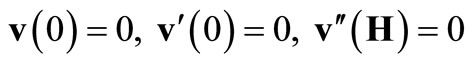 (4)
(4)
The matrices appearing in the above relations are described by the following formulae:
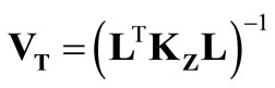 ,
,
 ,
,
 ,
,
 ,
,
 ,
,
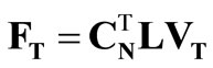
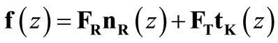

where the following notation applies:
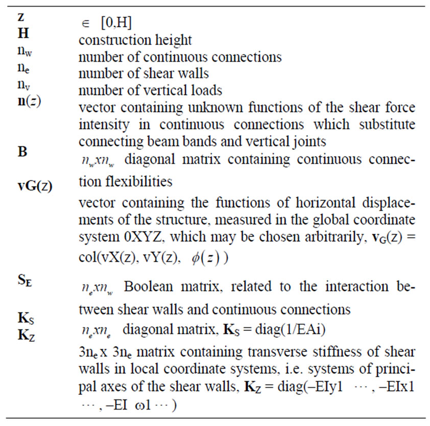

All necessary matrices and vectors are automatically computed.
The differential Equations (1) and (2) with the boundary conditions (3) and (4) are decoupled by orthogonal eigenvectors. Next, the uncoupled equations are exactly solved for the following loadcases.
3.2. Dynamic Analysis
The second subsystem is an extended version of DAMB (Dynamic Analysis of Multistorey Buildings [7, 8]). It is for analysis of coupled torsional-flexural vibration of shear wall multistorey structures due to seismic action moreover analyses the structure as a 3-D model. A dynamic model with masses in the form of rigid floor slabs has been adopted since over a half of building total mass is concentrated in the floor levels. Discrete masses may be free located throughout the height. Seismic response of structure is estimated by using the response spectrum technique.
The vibration of a multidegree of freedom system is described by relation:
 (5)
(5)
where:
M - mass matrix,
C - damping matrix,
K - stiffness matrix,
x - d-element vector of generalized coordinates (d - number of dynamic degrees of freedom of the calculated structure).
fD - d-element vector of generalized excitation forces, corresponding to generalized coordinates.
For a shear wall multistorey structure is more natural to determine the flexibility matrix D then the stiffness matrix K. The vibration of a structure is described by relation:
 (6)
(6)
The flexibility matrix is generated from the exact solution of the governing differential equation for a 3-D continuous model. Also mass matrix is generated exactly according to real distribution of walls, connecting beams and floor slabs and including flexural and torsional inertia.
The steps involved are: 1) determination of natural frequencies and mode shapes, 2) evaluation of modal participation factors and calculation of modal loading on the structure (using an appropriate design spectrum), 3) determining response estimate containing the contribution from the given number of modes for various parameters of interest (using three methods: SRSS—the square root of the sum of the squares, CQC—the complete quadratic combination, DSC—the double sum combination).
4. Analysis of the Examined Building
4.1. Dynamic Analysis
As a result of the first calculation step by DAMB, eigenfrequency and corresponding mode shapes for the old and new part of the building have been received. The eigenfrequency and mode shapes of the first 4 modes are presented in Figures 4 and 5.
The obtained eigenfrequency from the dynamic calculations let on the proper estimation of wind loading examined for both parts of analysed building (separated with the movement joint) based on the new Polish wind code (based on the Eurocode 1) [9].
4.2. Static Analysis
4.2.1. Static Analysis of an Existing Part
The requirements connected with the new function of the building resulted in the need of demolition of some load-bearing walls, which also were shear walls. To ensure the required space stiffness of the building, a few new shear walls were added. Due to this a detailed analysis of the existing part of the building was carried out on based on Integrated System. The wind load was taken into account. The model of the stiffening construction consisted of 23 walls, 12 vertical flexible joint bands and 7 lintel bands. The plan of this structure with the stress distribution at the bottom of the building, and the most stressed element and wall for the wind pressure scheme in the Y axis direction is presented in Figure 6.
Figure 7 shows the displacements for scheme 1 at wind pressure in X direction for the reconstructed existing part, and Figure 8 the displacements for scheme 2.
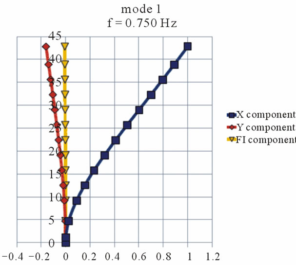
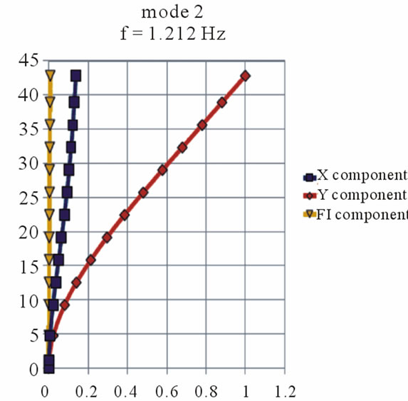
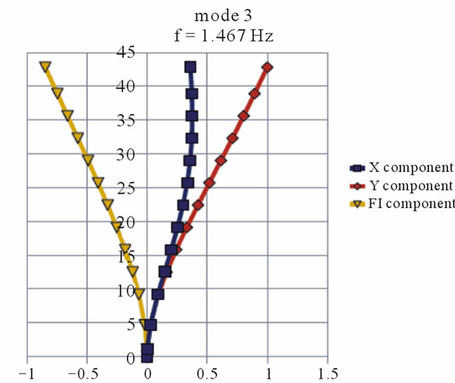
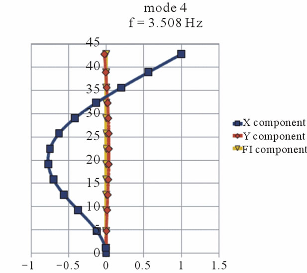
Figure 4. The eigenfrequency and corresponding mode shapes for the old part of the building.
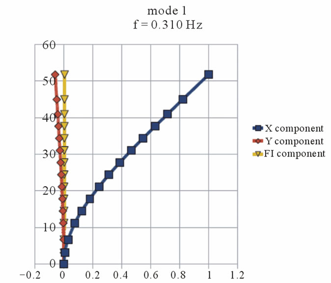
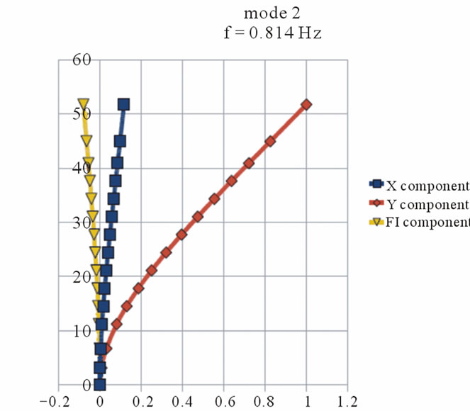
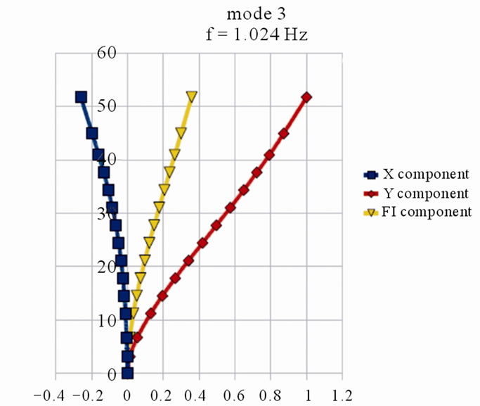
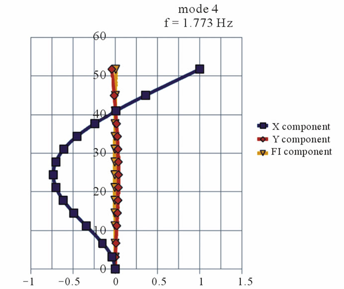
Figure 5. The eigenfrequency and corresponding mode shapes for the new part of the building.
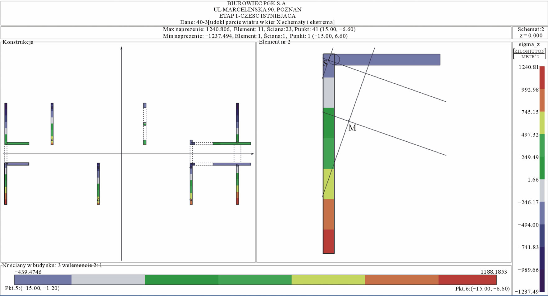
Figure 6. The layout of the reconstructed part of the object; the most stressed wall and the element containing the most stressed wall with the normal stress distribution at the bottom of the building.
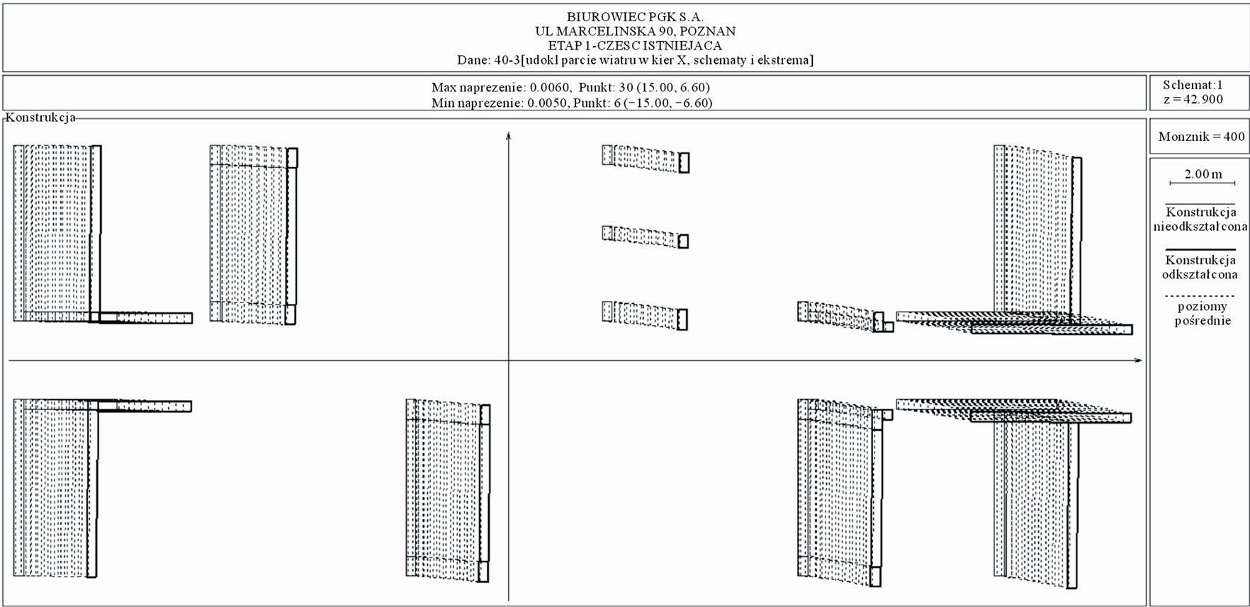
Figure 7. The existing part: displacements ×400, scheme 1.
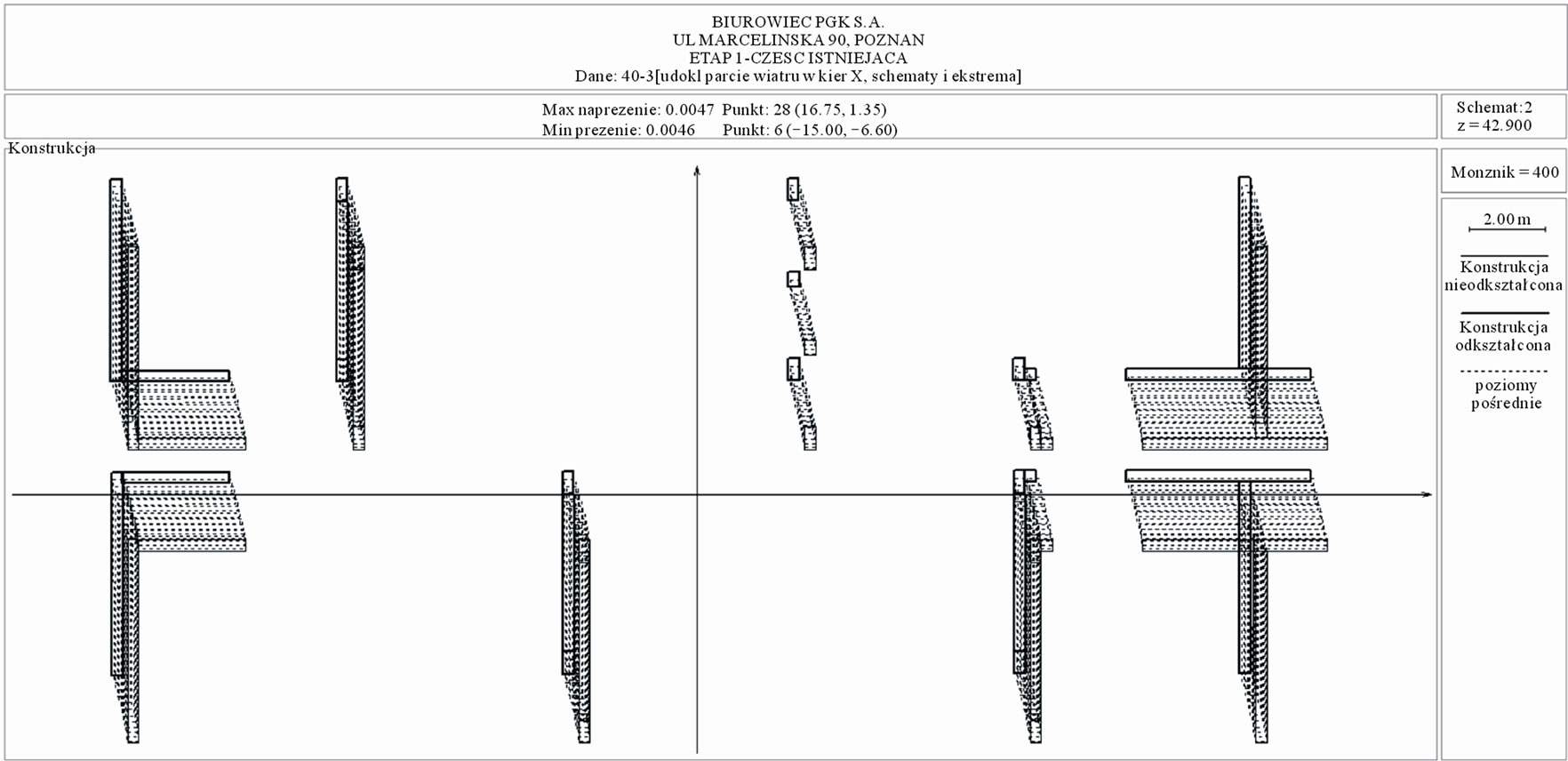
Figure 8. The existing part: displacements ×400, scheme 2.
4.2.2. Static Analysis of a New Part
The aim of the extension of the existing building was a full dilatation of the existing and new part. Therefore, the most important difficulty was designing the new structural system, that it would not affect unfavourably the existing part of the building. After a few trials (using Integrated System analysis) a stiffening structure was proposed. The model of the structure consisted of 28 walls, 18 vertical flexible joints bands and 7 vertical lintel bands. The plan of this structure with the normal stress distribution at the bottom of the building, and the most stressed element and wall for the wind pressure scheme in the X axis direction is presented in Figure 9.
Figure 10 shows the displacements for scheme 1 at wind pressure in X direction for the new part and Figure 11 the displacements for scheme 2.
The analysis using Integrated System showed, that the largest of the extreme displacements in the weakened, existing part had a value of 5.91 mm, and the largest of the extreme displacements in the new part was assessed
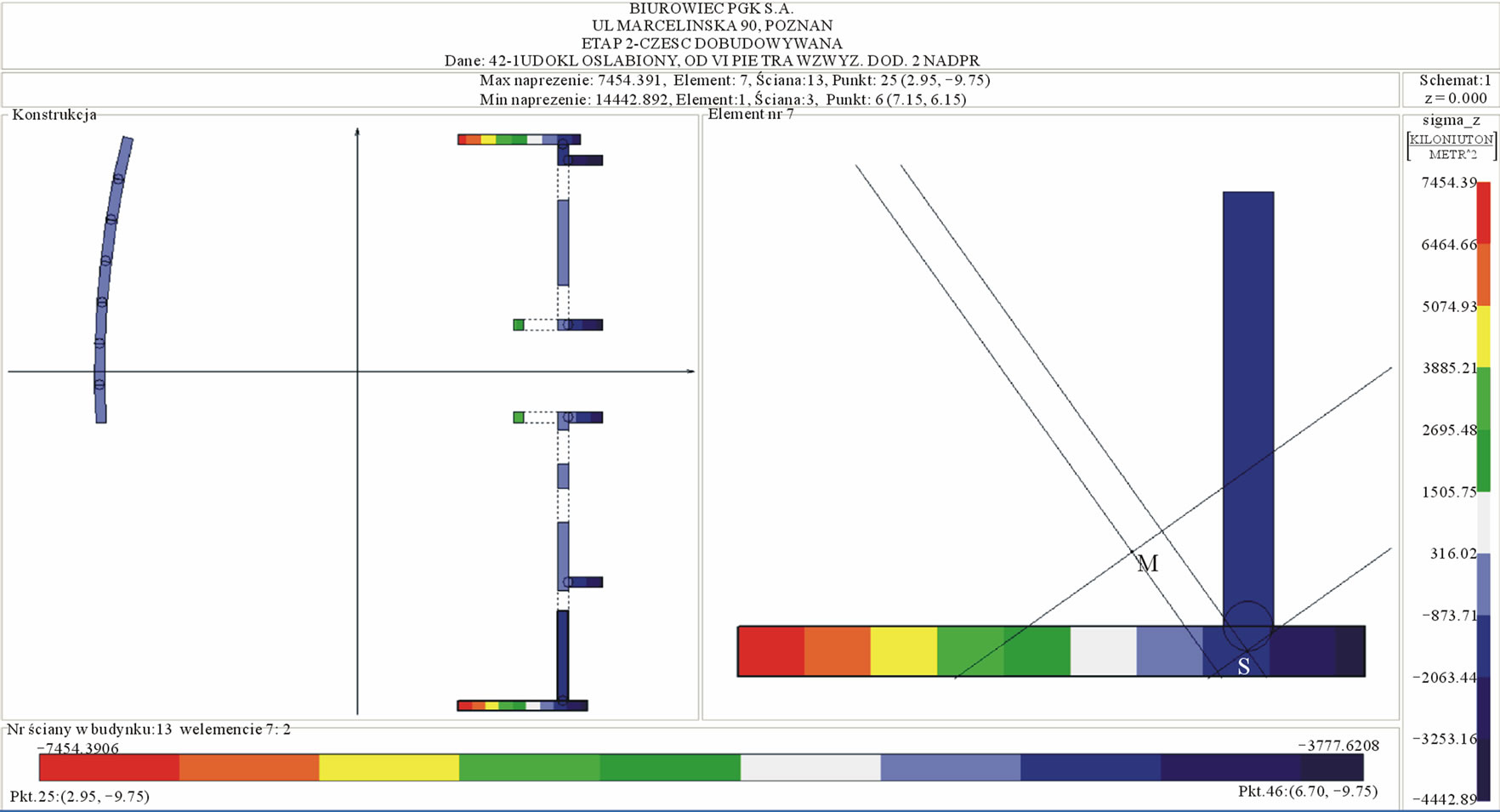
Figure 9. The new part of the building: the most stressed wall and the elem-ent containing the most stressed wall with the normal stress distri-bution at the bottom of the building.
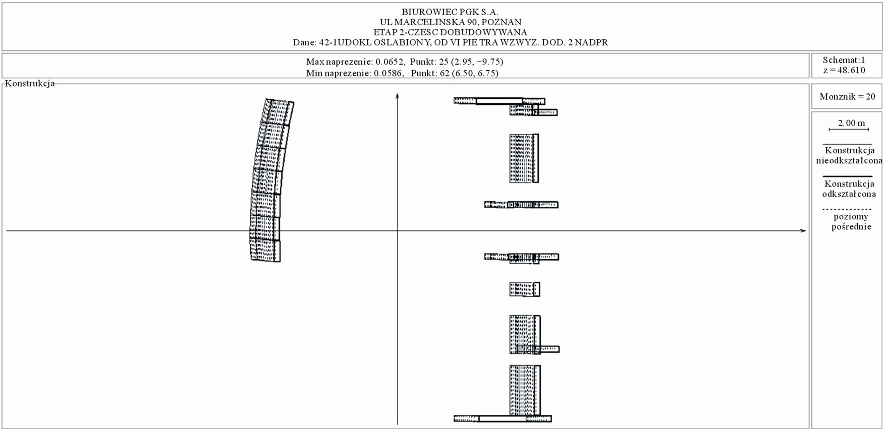
Figure 10. The new part of the building, the upper part (weakened system) displacements ×20, scheme 1.
at 62.14 mm. Thus, concerning too large displacements in the new part, a decision to increase the grade of the concrete used in the stiffening elements in this part of the structure was done. This action decreased the value of the calculated displacements to 48.47 mm.
As shown above, both the reconstructed existing structure and the new part showed the requires 3-D stiffness.
5. Conclusions
The conducted revitalization of a building initially intended for demolition resulted in creating one of the most modern office building in Poznan. The building, which was revitalized was adapted for its new functions and it fulfils the designed functions up to the present day. The
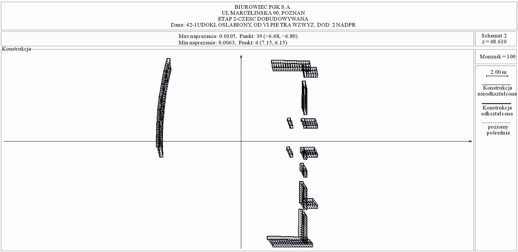
Figure 11. The new part of the building, the upper part (weakened system) displacements x 100, scheme 2.
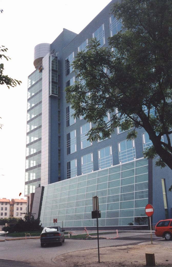
Figure 12. Analysed building after rehabilitation.
Integrated System gives a possibility to perform a full analysis of complex 3-D shear wall structures. It was thoroughly tested to prove the correctness of its work. An application of the system allows to perform effective, low cost analysis of stresses and displacements in nonsymmetrical structures with shear walls and connecting beams freely distributed in the plan. The analysis course confirmed the advantages of a continuous structural model as a convenient tool in the designing process. The short time of getting the analysis results and the use of postprocessors, enabling graphic results presentation, allowed interactive dimensioning of the building structure. The revitalised office building has been adapted to perform new functions and up till now it has been successfully functioning (Figure 12).
6. REFERENCES
- PN-EN 206-1, PN-EN 206-1:2003, Concrete. Specification, Performance, Production and Conformity, in Polish.
- B. Lewicki, et al. “Buildings Build with Industrialized Methods,” in Polish, Arkady, Warszawa, 1979.
- O. Aksogan, H. M. Arslan and B. S. Choo, “Forced Vibration Analysis of Stiffened Coupled Shear Walls Using Continuous Connection Method,” Engineering Structures, Vol. 25, No. 4, 2003, pp. 499-506. doi:10.1016/S0141-0296(02)00192-X
- G. Q. Li and B. S. Choo, “A Continuous-Discrete Approach to the Free Vibration Analysis of Stiffened Pierced Walls on Flexible Foundations,” International Journal of Solids and Structures, Vol. 33, No. 2, 1996, pp. 249-263. doi:10.1016/0020-7683(95)00028-9
- J. Wdowicki, E. Wdowicka and T. Błaszczyński, “Integrated System for Analysis of Shear Wall Tall Buildings,” Proceeding of the Fifth World Congress on Habitat and High-Rise: Tradition and Innovation, Council on Tall Buildings and Urban Habitat, Amsterdam, 1995, pp. 1309-1324.
- J. Wdowicki and E. Wdowicka, “System of Programs for Analysis of Three-Dimensional Shear Wall Structures,” The Structural Design of Tall Buildings, Vol. 2, No. 4, 1993, pp. 295-305. doi:10.1002/tal.4320020403
- J. Wdowicki, E. Wdowicka and T. Błaszczyński, “System of Programs for Dynamic Analysis of Shear Wall Tall Buildings,” Proceeding of the International Conference on Lightweight Structures in Civil Engineering, Warsaw Univ. of Technology, Warsaw, 1995, pp. 440-445.
- E. Wdowicka, J. Wdowicki and T. Błaszczyński, “Seismic Analysis of the “South Gate” Tall Building According to Eurocode 8,” The Structural Design of Tall and Special Buildings, Vol. 14, No. 1, 2005, pp. 59-67. doi:10.1002/tal.261
- Eurocode 1: Actions on structures—Part 1-4: General Actions—Wind Actions on Structures, in Polish, PN-EN 1991-1-4: 2008.