Engineering
Vol. 2 No. 10 (2010) , Article ID: 3175 , 9 pages DOI:10.4236/eng.2010.210098
Modelling and Optimisation of a Spring-Supported Diaphragm Capacitive MEMS Microphone
1Faculty of Engineering and Industrial Sciences, Swinburne University of Technology, Hawthorn, Australia
2School of Electrical and Computer Engineering, RMIT University, Melbourne, Australia
E-mail: norizan@utem.edu.my
Received June 9, 2010; revised September 6, 2010; accepted September 21, 2010
Keywords: Capacitive Microphone, Spring-Supported Diaphragm, Microphone Modelling
ABSTRACT
Audio applications such as mobile communication and hearing aid devices demand a small size but high performance, stable and low cost microphone to reproduce a high quality sound. Capacitive microphone can be designed to fulfill such requirements with some trade-offs between sensitivity, operating frequency range, and noise level mainly due to the effect of device structure dimensions and viscous damping. Smaller microphone size and air gap will gradually decrease its sensitivity and increase the viscous damping. The aim of this research was to develop a mathematical model of a spring-supported diaphragm capacitive MEMS microphone as well as an approach to optimize a microphone’s performance. Because of the complex shapes in this latest type of diaphragm design trend, analytical modelling has not been previously attempted. A novel diaphragm design is proposed that offers increased mechanical sensitivity of a capacitive microphone by reducing its diaphragm stiffness. A lumped element model of the spring-supported diaphragm microphone is developed to analyze the complex relations between the microphone performance factors and to find the optimum dimensions based on the design requirements. It is shown analytically that the spring dimensions of the spring-supported diaphragm do not have large effects on the microphone performance com pared to the diaphragm and backplate size, diaphragm thickness, and air-gap distance. A 1 mm2 spring-supported diaphragm microphone is designed using several optimized performance parameters to give a –3 dB operating bandwidth of 10.2 kHz, a sensitivity of 4.67 mV/Pa (–46.5 dB ref. 1 V/Pa at 1 kHz using a bias voltage of 3 V), a pull-in voltage of 13 V, and a thermal noise of –22 dBA SPL.
1. Introduction
The silicon capacitive microphone has been studied and shown to potentially replace the existing and widely used piezoelectric microphone due to its high sensitivity, long term stability and ability to withstand a high temperature soldering process [1,2]. This type of microphone has been designed to use various diaphragm materials including silicon nitride, polysilicon, aluminum, and polyimide [3-6]. A different diaphragm material was chosen to suit the intended application based on the required dimension, sensitivity, and operating frequency range. Open-circuit sensitivity of a capacitive microphone can be increased by applying a higher bias voltage or reducing the diaphragm stiffness. Since many small size audio applications prefer a low voltage operation, the microphone sensitivity needs to be increased by reducing the diaphragm stiffness alone. The diaphragm stiffness can be reduced by using a low stress material, perforated diaphragm or as a combination with corrugated or spring type diaphragm [4,6-12]. However, the reduction in diaphragm stiffness will cause the reduction in its operating frequency range and pull-in voltage. Moreover, the desired smaller device size and capacitor air-gap thickness will increase the thin film air damping effect which will decrease its open-circuit sensitivity further. Due to the trade-offs relation between these performance factors, the optimization of the microphone parameters is always required depending on the design requirements.
Previous research has been carried out using various spring type diaphragm to increase the sensitivity of a capacitive MEMS microphone. Kim et al. [11] has demonstrated the use of a flexure hinge diaphragm to achieve 0.2 m diaphragm centre deflection with a flat frequency range of up to 20 kHz. Weigold et al. [13] was using a spring-supported, thin polysilicon diaphragm fabricated on silicon on insulator (SOI) wafer to achieve a sensitivity of –47 dB (ref 1 V/Pa) with the amplifier circuit. Another high sensitivity of up to 8.2 mV/Pa was reported by Fuldner et al. [9] using a spring type diaphragm membrane of 1 mm in diameter and low bias voltage of 1 V. Mohamad et al. [12,14] has also demonstrated that a specially designed spring-supported diaphragm can easily achieve up to 100 times higher mechanical sensitivity and 1.5 times higher capacitance change compared to the edge-clamped diaphragm of the same size.
The behaviour of a capacitive microphone can be simplified and represented using linear lumped elements in a reduced-order network modelling. An accurate model will speed-up design analysis and parameters optimization using finite element analysis (FEA). In network modelling method, the electrical linear lumped elements were determined from the acoustical and mechanical structure of the microphone. The diaphragm compliance has the greatest influence on the microphone sensitivity, thus its analytical expression needs to be determined accurately. A detailed analysis to determine the compliance of a circular spring diaphragm has been reported by Fuldner et al. [9].
A novel spring type diaphragm design is proposed that provides increased mechanical sensitivity of a capacitive microphone by reducing its diaphragm stiffness compared to traditional designs. This paper aims to develop a mathematical model of the spring supported diaphragm microphone design and optimize its performance. Spring type diaphragms are the latest design approaches in capacitive microphone research, and analytical modelling of this type diaphragm has not been previously attempted because of the complex shapes. A lumped element model of the spring-supported diaphragm microphone is derived to analyze the complex relations between the microphone performance factors and to find its optimum parameters setting based on the design requirements.
2. Microphone Design and Modelling
This section first describes the development of equations to model the centre deflection of the diaphragm, and then determines equations for the open-circuit sensitivity, frequency response, pull-in voltage and the mechanical thermal noise of the microphone.
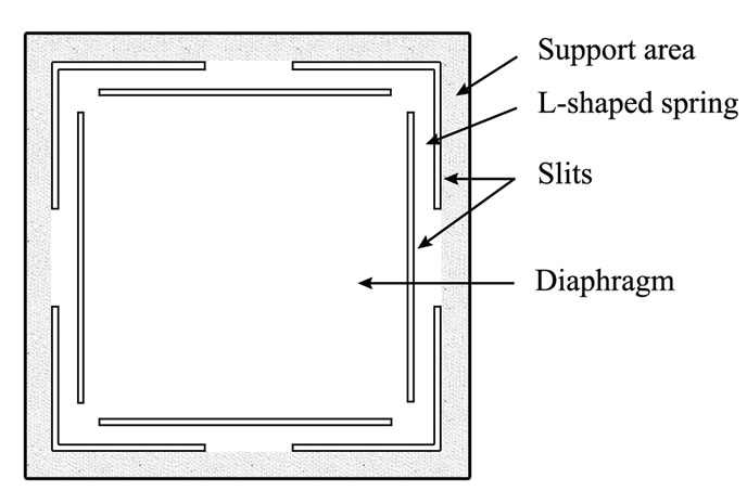
The spring-supported diaphragm presented in this paper has a structure as shown in Figure 1. The square diaphragm is suspended by four L-shape spring at its four corners. Its matched size backplate with several perforated holes is shown in Figure 2. The cross-sectional view of the microphone structure is shown in Figure 3. A mathematical model to describe the diaphragm movement under an oscillating sound pressure was developed by dividing the diaphragm in Figure 1(a) into two main parts:
1) A diaphragm with four corners simply supported by a fixed point in Figure 1(c) (see Figure 4), and 2) Four doubly clamped L-shaped springs in Figure 1(c) (see Figure 6).
 (a)
(a)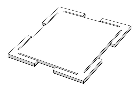 (b)
(b)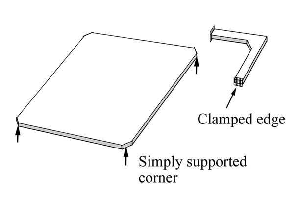 (c)
(c)
Figure 1. Microphone diaphragm structure showing a square diaphragm with four L-shaped springs attached: (a) top-view and (b) 3D view, and (c) a square diaphragm with four simply supported corners and one of the four L-shaped springs with its clamped edges.
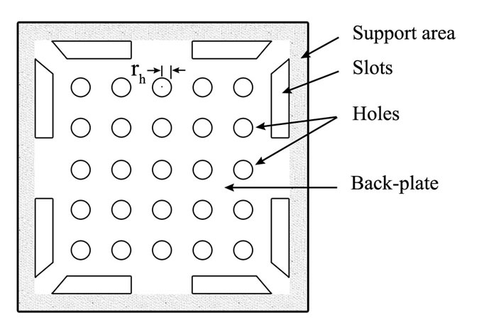
Figure 2. Microphone back-plate structure with perforated holes.
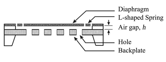
Figure 3. Microphone cross-sectional view.
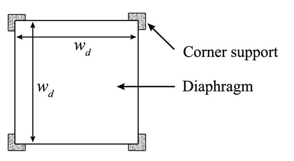
Figure 4. Corner supported diaphragm.
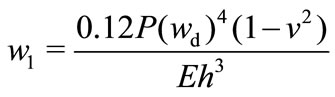
Assuming a linear displacement, the corner-supported diaphragm’s center deflection, w1 in Figure 4 is given by [15]:
 (1)
(1)
where P is the sound pressure perpendicular to the top of the diaphragm in Pascal, h is the diaphragm thickness, wd is the diaphragm length and width. E and v are the modulus of elasticity, and Poisson’s ratio of the diaphragm material respectively.
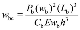
The deflection of an L-shaped spring is derived from a doubly-clamped beam center deflection [16]. Assuming small and linear diaphragm deflection, a center beam deflection, wbc in Figure 5 is given by:
 (2)
(2)
where wb is the beam width, h and Lb are the beam thickness and beam length respectively. The constant factor Cb was determined using Coventor MEMS design software by varying the beam thickness, width, and length to give Cb ≈ 17.4. Modifying (2) by introducing a factor C1 to compensate the differences between the doubly-clamped beam and the L-shaped spring deflection in Figure 6 gives:
 (3)
(3)
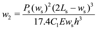
where w2 is the L-shaped spring center deflection, h , ws , and Ls are the spring thickness, spring width, and spring length respectively.
Since the microphone diaphragm’s corner is attached to the center of the L-shaped spring, (3) was modified to include the effect of diaphragm's corner deflection to give:
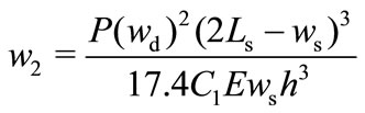 (4)
(4)
The centre deflection of the square spring-supported diaphragm, wc for small diaphragm deflection (wc < h) is given by the sum of the diaphragm deflection in (1) and L-shaped spring deflection in (4):
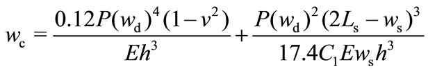 (5)
(5)
Figure 7 shows the numerical relationship of factor, C1 with the diaphragm thickness. The relationship was found using the Coventor to model a spring diaphragm microphone with parameters in Table 1. A linear curve fitting on the graph gives:
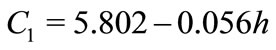 (6)
(6)
2.1. Open-Circuit Sensitivity
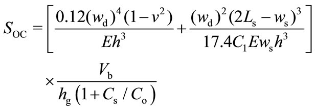
A capacitive microphone operates using the principle of a variable capacitor which produces a variable output voltage when one of its charged capacitor plate is moving parallel to the other plate, thus varying its plate gap. The open-circuit sensitivity (in Volt per Pascal) of a capacitive microphone is given by [17]:
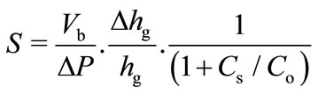 (7)
(7)
where Vb is the bias voltage (in volt), hg is the sound pressure change, Co is the initial air gap distance (in meter) between microphone diaphragm and its back plate, and Cs are the microphone initial capacitance and stray capacitance (in Farad) respectively. The initial or working capacitance can be calculated using the parallel-plate capacitor equation. The narrow air gap in this microphone leads to an increase in the viscous damping. A number of back plate holes was used to reduce the viscous damping effect [18,19] (see Figure 2). Substracting the back plate holes from the back plate area and assuming a flat diaphragm deflection, the initial capacitance, Co is given by:
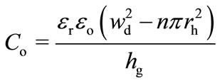 (8)
(8)
where εr is the dielectric constant of the air gap ( εr ≈ 1 for air), εo is the absolute permittivity of a vacuum, n and rh are the number of back-plate holes and hole radius respectively.
Substituting (5) for the Δhg into (7) yields a frequency dependent open-circuit sensitivity of a spring diaphragm microphone:
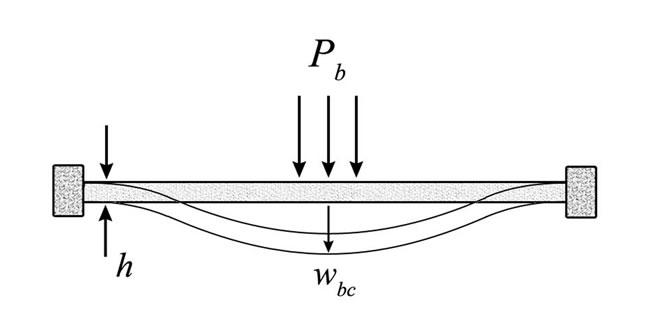
Figure 5. Doubly-clamped beam center deflection.
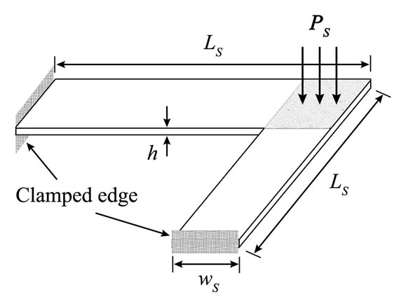
Figure 6. L-shaped spring dimensions.
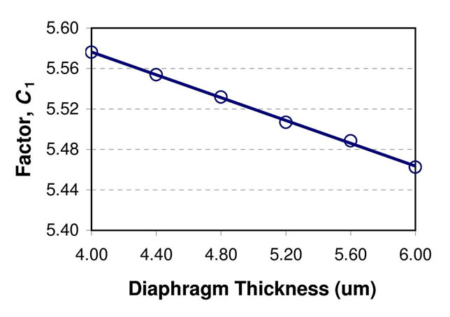
Figure 7. A linear curve fitting for factor C1 vs. diaphragm thickness.
 (9)
(9)
2.2. Frequency Response
A capacitive microphone is often designed to operate in a desired operating frequency range. The frequency response of the microphone must be flat within the desired range to reproduce a good quality sound. In this paper, the microphone will be designed to operate in an audio operating bandwidth of up to 20 kHz. Table 1 shows the optimized parameters for the microphone design discussed in Section 3.
The frequency response of a condenser microphone can be analyzed using linear lumped elements in a network modelling. Figure 8 shows an equivalent circuit diagram to represent various lumped elements of a condenser MEMS microphone where Fs is the sound pressure force, and Vm is the sound velocity.
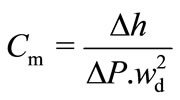
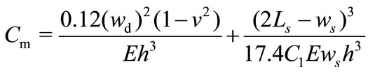
The mechanical compliance, Cm of the diaphragm is given by [17]:
 (10)
(10)
Substituting (5) for Δh into (10) gives a spring-supported diaphragm compliance (in meter-/Newton):
 (11)
(11)
The lumped effective mass, Mm (in kg) of the microphone can be approximated by the total diaphragm and L-shaped spring mass:
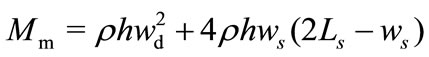 (12)
(12)
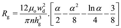
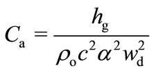
where ρ is the polysilicon density for both diaphragm and L-shaped spring. The air gap viscosity loss, Rg (in N.s/m) and its compliance, Ca (in m/N) can be expressed as [20]:
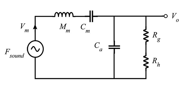
Figure 8. Equivalent circuit diagram of a MEMS microphone.
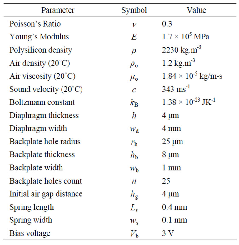
Table 1. Microphone parameters used for the numerical simulations.
 (13)
(13)
 (14)
(14)
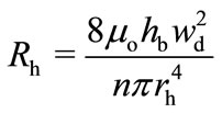
where μo and ρo are the viscosity and density of air respectively, n is the number of backplate holes, hg is the air-gap distance with zero bias voltage, α is the surface fraction occupied by the backplate holes, and c is the sound velocity at room temperature. The backplate holes viscosity loss, Rh (in N.s/m) is given by [17]:
 (15)
(15)
The total impedance, Zt of the circuit in Figure 8 can be expressed as:
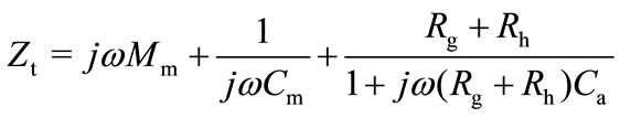 (16)
(16)
Thus, the frequency dependent sensitivity and frequency response of the microphone (in Volt/Pascal) can be calculated as:
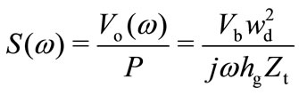 (17)
(17)
2.3. Pull-In Voltage
A capacitive microphone’s pull-in voltage is caused by the attractive force between the diaphragm and backplate when a constant bias voltage is applied during its operation. Its value is mainly determined by the spring restoring force of the diaphragm [21] and the L-shaped spring in this paper. Assuming a linear spring restoring force, the net force, Fnet acting on upper plate (diaphragm and L-shaped spring) is given by [16]:
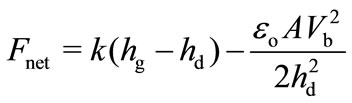 (18)
(18)
where spring constant, k can be calculated from the inverse of the spring-supported diaphragm compliance ( k = 1/Cm ), hg and hd are the air-gap distance with zero and constant bias voltage respectively. A is the effective parallel plate area (backplate area minus area occupied by the holes). The first part of the expression in (18) is the spring upward force by the diaphragm and L-shaped spring, and the second part of the expression is the downward electrostatic force caused by the constant bias voltage. At equilibrium, the net force is equal to zero:
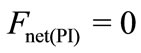 (19)
(19)
The pull-in occurs at the air-gap distance [16]:
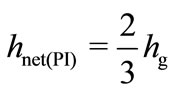 (20)
(20)
Equating (18) and (19), and substituting (20) for the pull-in air-gap yields:
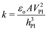 (21)
(21)
where VPI is the pull-in voltage at pull-in air-gap distance, hPI. Substituting (20) into (21) yields the pull-in voltage, VPI expression:
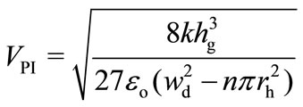 (22)
(22)
2.4. Mechanical Thermal Noise
A good capacitive microphone is designed to pick up the lowest possible sound pressure which is limited by the mechanical thermal noise and the preamplifier noise of the microphone [19]. The A-weighted mechanical thermal noise, SN (in Pascal) can be calculated by [19]:
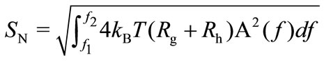 (23)
(23)
where f1 and f2 are 20 Hz and 20 kHz respectively, T is the Boltzmann constant, and A(f) is the absolute temperature (in Kelvin). The A-weighted filter function, is given by:
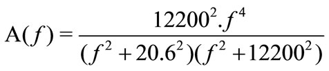
 (24)
(24)
where f is the sound pressure frequency in Hertz.
It can be seen in (23) that a mechanical thermal noise can be reduced by reducing the backplate holes viscous damping. However, the viscous damping reduction will increase the resonant peak of the microphone diaphragm. Thus, optimum parameters need to be calculated to get the lowest mechanical thermal noise according to the frequency response requirements.
3. Performance Analysis
A capacitive MEMS microphone performance factors such as sensitivity, operating bandwidth, pull-in voltage, and thermal noise can be analyzed by varying some of its structural parameters. Table 2 shows the microphone parameters’ change from a low to a higher value which was shown as a percentage parameter change in the analysis graphs throughout this section. Since only one parameter is changed at a time, all other parameters used in the performance analysis simulations are fixed at a reference value as shown in Table 1.
The following sections analyses the effect of viscous damping and structure dimensions on bandwidth, sensitivity, pull-in voltage and thermal noise. The results are then used to determine optimised parameters and the frequency response of the diaphragm.
3.1. Viscous Damping
Viscous damping of a MEMS microphone is largely affected by the air gap and backplate viscosity loss as in Equations (13) to (15). In this section, the spring-supported microphone’s air gap distance, backplate hole count and hole radius were varied as in Table 2 to observe its performance effects. Figure 9 shows that the –3dB operating bandwidth of the microphone can be increased gradually by increasing the backplate hole radius and hole count. Although a larger operating bandwidth can easily be achieved by having more backplate holes and larger hole radius, this decreases the microphone sensitivity as shown in Figure 10. Also, these two parameters changes have negligible effect on the pull-in voltage value (see Figure 11).
An increase in air gap on the other hand reduces the operating bandwidth (Figure 9) even though it increases the pull-in voltage gradually as shown in Figure 11. The aim of a microphone design is to achieve the highest sensitivity, adequate operating bandwidth (20 kHz for an audio applications), and at least 3 times higher pull-in voltage than its bias voltage to prevent the diaphragm from collapsing to the backplate during microphone normal operation.

Table 2. Microphone parameters’ changes used for the performance analysis simulations.
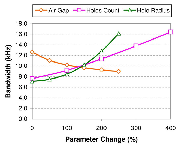
Figure 9. Microphone bandwidth with air-gap distance, number of backplate holes (holes count), and backplate hole radius change.
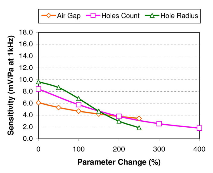
Figure 10. Microphone sensitivity with air-gap distance, number of backplate holes (holes count), and backplate hole radius change.

Figure 11. Microphone pull-in voltage with air-gap distance, number of backplate holes (holes count), and backplate hole radius change.
The A-weighted mechanical thermal noise of the spring-supported microphone is shown to be decreasing with the decrease of viscous damping (see Figure 12). Also, the noise value is shown to be several dBs below the lowest hearing threshold (0 dBA SPL) even at the higher viscous damping values.
3.2. Structure Dimensions
A microphone’s open-circuit sensitivity and its frequency response are dependent on viscous damping, as discussed previously, as well as its structure dimensions as in Equations (9) and (17). Figure 13 shows that an increase in spring width has little effect on the operating bandwidth, but slowly reduces the sensitivity as shown in Figure 14. The increase in spring width, however, does raise the pull-in voltage slightly (see Figure 15). In contrast, the use of a longer spring in a spring-supported MEMS microphone reduces the microphone operating bandwidth and pull-in voltage slightly (see Figure 13 and Figure 15) even though it causes a small increase in microphone sensitivity (Figure 14).
Significant microphone performance effects can be seen by varying the diaphragm and backplate width, as well as the diaphragm thickness. Increasing the diaphragm and backplate width will obviously increases the capacitor effective area thus increasing its capacitance. This is reflected by the large increase in microphone sensitivity as shown in Figure 14. However, the diaphragm width increase will also reduce its spring constant, thus gradually reducing the microphone operating bandwidth (Figure 13), as well as the pull-in voltage (Figure 15).
Increasing a diaphragm’s thickness will increase its spring constant, however this will reduce its operating bandwidth up to about 200% thickness change before the bandwidth begins to increase slightly (see Figure 13). A thicker microphone diaphragm gives a higher pull-in voltage (Figure 15) but reduces the sensitivity due to a higher spring constant (Figure 14).
The A-weighted mechanical thermal noise is shown not to be affected by variations in diaphragm thickness, spring width and spring length, however the noise becomes greater with the increase in diaphragm and backplate width due the increased in the capacitor area which will increase the microphone’s air gap and the backplate holes viscosity loss (see Figure 16). Similar to the viscous damping case, the noise value here is shown to be more than 10 dB below the lowest hearing threshold (0 dBA SPL).
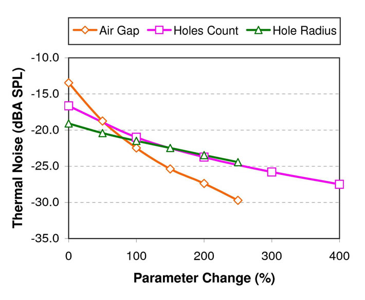
Figure 12. Microphone thermal noise with air-gap distance, number of backplate holes (holes count), and backplate hole radius change.
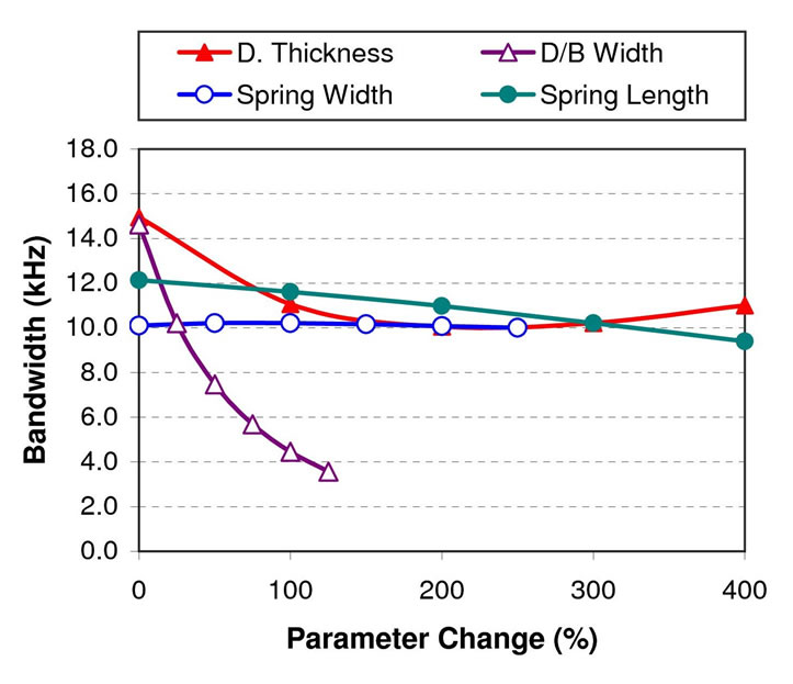
Figure 13. Microphone bandwidth with diaphragm thickness, diaphragm and backplate width, spring width, and spring length change.
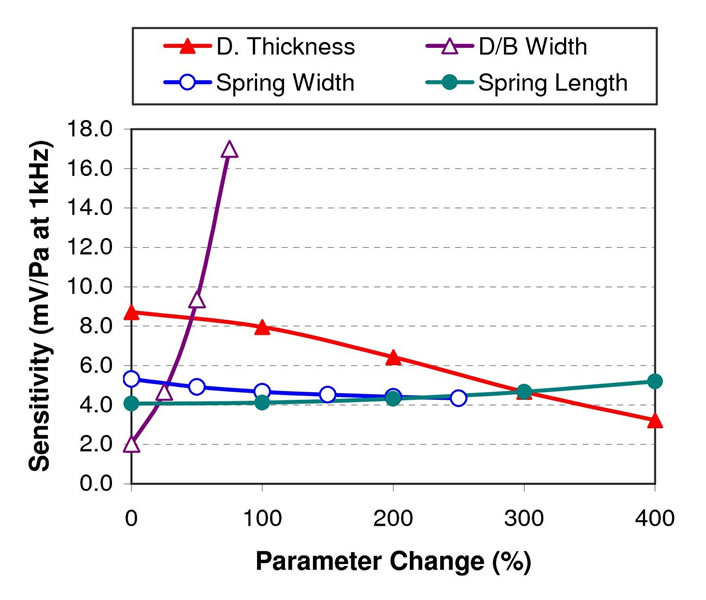
Figure 14. Microphone sensitivity with diaphragm thickness, diaphragm and backplate width, spring width, and spring length change.
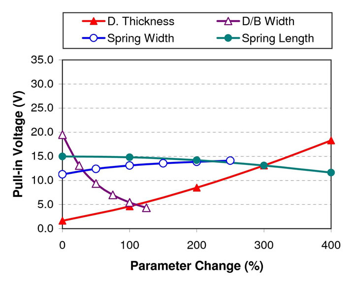
Figure 15. Microphone pull-in voltage with diaphragm thickness, diaphragm and backplate width, spring width, and spring length change.
3.3. Parameters Optimization
Parameters optimization is required to achieve the best microphone performance given various design and application constraints such as smaller device size, wider operating bandwidth, and minimum electrical power usage. In this paper, a spring-supported diaphragm microphone requires 20 kHz operating bandwidth with highest sensitivity and pull-in voltage, as well as the lowest possible thermal noise.
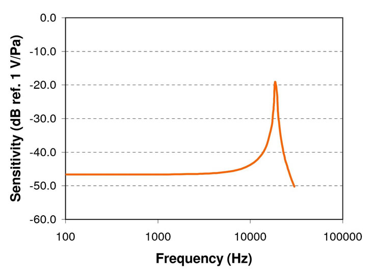
Based on the complex parameters relationships as discussed in previous sections, an optimised microphone design was achieved using the parameter values shown in Table 1. The design gives a –3dB operating bandwidth of 10.2 kHz, a sensitivity of 4.67 mV/Pa (–46.5 dB ref. 1 V/Pa at 1 kHz using a bias voltage of 3 V), a pull-in voltage of 13 V, and a thermal noise of –22 dBA SPL. The theoretical frequency response of the microphone was calculated using (17) and is shown in Figure 17.
4. Conclusions
The design of a spring-supported microphone is governed by a complex relations and trade-offs between several performance factor parameters. Since optimum parameter values are required for a microphone’s performance, a lumped element model is developed to assist in achieving this goal. The model is applied to a novel spring-supported diaphragm capacitive microphone design, and it is concluded that the spring width and length in the spring-support do not have a large effect on the microphone’s operating bandwidth, sensitivity, pull-in voltage, and thermal noise.
An optimum set of parameter values are used for the new spring-supported diaphragm microphone to give a –3
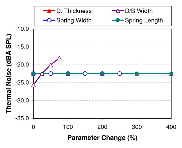
Figure 16. Microphone thermal noise with diaphragm thickness, diaphragm and backplate width, spring width, and spring length change.
dB operating bandwidth of 10.2 kHz, a sensitivity of 4.67 mV/Pa (–46.5 dB ref. 1 V/Pa at 1 kHz using a bias voltage of 3 V), a pull-in voltage of 13 V, and a thermal noise of –22 dBA SPL. The operating bandwidth of the microphone can be increased further by using a thicker diaphragm size with a trade-off of lowering its sensitivity. However, a lower sensitivity can easily be increased by using a higher bias voltage if it is permitted by the intended application and does not exceed the pull-in voltage threshold of the diaphragm.
REFERENCES
- C. P. R. Scheeper, A. G. H. Van Der Donk, W. Olthuis and P. Bergveld, “Review of silicon microphones,” Sensors and Actuators, A: Physical, Vol. 44, No. 1, 1994, pp. 1-11.
- P. Rombach, M. Mullenborn, U. Klein and K. Rasmussen, “The First Low Voltage, Low Noise Differential Silicon Microphone, Technology Development and Measurement Results,” Sensors and Actuators, A: Physical, Vol. 95, No. 2-3, 2002, pp. 196-201.
- P. R. Scheeper, W. Olthuis and P. Bergveld, “Silicon Condenser Microphone with a Silicon Nitride Diaphragm and Backplate,” Journal of Micromechanics and Microengineering, Vol. 2, No. 3, 1992, pp. 187-189.
- A. Torkkeli, O. Rusanen, J. Saarilahti, H. Seppa, H. Sipola and J. Hietanen, “Capacitive Microphone with LowStress Polysilicon Membrane and High-Stress Polysilicon Backplate,” Sensors and Actuators, A: Physical, Vol. 85, No. 1-3, 2000, pp. 116-123.
- M. Pedersen, R. Schellin, W. Olthuis and P. Bergveld, “Electroacoustical Measurements of Silicon Microphones on Wafer Scale,” Journal of the Acoustical Society of America, Vol. 101, No. 4, 1997, pp. 2122-2128.
- B. A. Ganji and B. Y. Majlis, “Design and Fabrication of a New MEMS Capacitive Microphone Using a Perforated Aluminum Diaphragm,” Sensors and Actuators, A: Physical, Vol. 149, No. 1, 2009, pp. 29-37.
- P. R. Scheeper, W. Olthuis and P. Bergveld, “Design, Fabrication, and Testing of Corrugated Silicon Nitride Diaphragms,” Journal of Microelectromechanical Systems, Vol. 3, No. 1, 1994, pp. 36-42.
- X. Li, R. Lin, H. Kek, J. Miao and Q. Zou, “Sensitivity-Improved Silicon Condenser Microphone with a Novel Single Deeply Corrugated Diaphragm,” Sensors and Actuators, A: Physical, Vol. 92, No. 1-3, 2001, pp. 257-262.
- M. Fuldner, A. Dehe and R. Lerch, “Analytical Analysis and Finite Element Simulation of Advanced Membranes for Silicon Microphones,” IEEE Sensors Journal, Vol. 5, No. 5, 2005, pp. 857-862.
- B. A. Ganji and B. Y. Majlis, “Design and Fabrication of a Novel Single-Chip MEMS Capacitive Microphone Using Slotted Diaphragm,” Journal of Micro/Nanolithography, MEMS, and MOEMS, Vol. 8, No. 2, 2009.
- H. J. Kim, S. Q. Lee and K. H. Park, “A Novel Capacitive Type Miniature Microphone with a Flexure Hinge Diaphragm,” Proceedings of SPIE—The International Society for Optical Engineering, Vol. 6374, Boston, 2006.
- N. Mohamad, P. Iovenitti and T. Vinay, “High sensitivity capacitive MEMS microphone with spring supported diaphragm,” Proceedings of SPIE—The International Society for Optical Engineering, SPIE, Canberra, Australia, 2008, pp. 68001T-1 until 68001T-9.
- J. W. Weigold, T. J. Brosnihan, J. Bergeron and X. Zhang, “A MEMS Condenser Microphone for Consumer Applications,” Proceedings of the IEEE International Conference on Micro Electro Mechanical Systems (MEMS), Istanbul, 2008, pp. 86-89.
- N. Mohamad, P. Iovenitti and T. Vinay, “Effective Diaphragm Area of Spring-Supported Capacitive MEMS Microphone Designs,” Proceedings of SPIE—The International Society for Optical Engineering, SPIE, Melbourne, Australia, 2008, pp. 726805-1 until 726805-7.
- S. Timoshenko and S. Woinowsky-Krieger, “Theory of Plates and Shells,” Mcgraw-Hill, New York, 1959, pp. 180-228.
- S. D. Senturia, “Microsystem Design,” Kluwer Academic, London, 2001, pp. 239-265.
- J. Bergqvist, “Finite-Element Modelling and Characterization of a Silicon Condenser Microphone with a Highly Perforated Backplate,” Sensors and Actuators, A: Physical, Vol. 39, No. 3, 1993, pp. 191-200.
- J. Bergqvist, F. Rudolf, J. Maisano, F. Parodi and M. Rossi, “A Silicon Condenser Microphone with a Highly Perforated Backplate,” IEEE International Conference on Solid-State Sensors and Actuators, San Francisco, CA, USA, 1991, pp. 266-269.
- C. W. Tan, Z. Wang, J. Miao and X. Chen, “A Study on the Viscous Damping Effect for Diaphragm-Based Acoustic MEMS Applications,” Journal of Micromechanics and Microengineering, Vol. 17, No. 11, 2007, pp. 2253-2263.
- P. C. Hsu, C. H. Mastrangelo and K. D. Wise, “High Sensitivity Polysilicon Diaphragm Condenser Microphone,” Proceedings of the IEEE Micro Electro Mechanical Systems (MEMS), Heidelberg, Germany, 1998, pp. 580-585.
- S. Chowdhury, M. Ahmadi and W. C. Miller, “Nonlinear Effects in MEMS Capacitive Microphone Design,” Proceedings International Conference on MEMS, NANO and Smart Systems, 2003, pp. 297-302.