Journal of Modern Physics
Vol. 4 No. 10B (2013) , Article ID: 38733 , 6 pages DOI:10.4236/jmp.2013.410A2002
Consideration of Viscoelasticity in Time Step FEM-Based Restraint Analyses of Hardening Concrete
Institute of Structural Concrete, Graz University of Technology, Graz, Austria
Email: dirk.schlicke@tugraz.at
Copyright © 2013 Dirk Schlicke, Nguyen Viet Tue. This is an open access article distributed under the Creative Commons Attribution License, which permits unrestricted use, distribution, and reproduction in any medium, provided the original work is properly cited.
Received August 17, 2013; revised September 16, 2013; accepted October 18, 2013
Keywords: Viscoelasticity; Hardening Mass Concrete; FEM Restraint Analysis; Time Dependant Material Properties; Hydration Heat; Evolution of Stiffness; Quantification of Restraint Stresses; In-Situ Measurements; Recalculation of Measurement Data
ABSTRACT
Concrete structures may suffer considerable restraint stresses during their hardening period. This is caused by several deformation impacts, especially temperature field changings due to hydration heat and volume changes due to autogenous shrinkage. Mainly affected are massive concrete members, but also the application of new concrete types or the erection of outstanding constructions requires further investigations in this context. 3D-FEM analyses of hydration heat induced temperature development in combination with the well known shrinkage give sufficient results for the deformation impact. The according elastic restraint stresses can be determined with consideration of the concrete’s rising elastic modulus and the restraint degree of the system. But due to duration of the heat flow process, the height of restraint stresses is strongly dependent from the viscoelasticity of the concrete. The viscoelastic effects consist of many components constituted by changing material properties influencing themselves. In practice, different simplified approaches are available for considering this in calculations. Their implementation in time step analyses is not generally admitted and requires expertise. In contrast, present research develops material models needing specific input parameters for every use case. This contribution focuses on a practicable approach considering the superposition of the viscoelastic behaviour of every stress increment in time step FEM analysis. The differentiation between the pure viscoelastic material behaviour (as it is given in the codes for idealistic conditions like creep or relaxation) and the according viscoelastic system response (addicted to the systems variable restraint degree) allows the transfer of this model into practice. As one application example of this approach, the compatibility check and the FEM-based recalculation of the monitoring program of a massive power plant slab will be presented.
1. Introduction
The behaviour of concrete structures could be considerably influenced by hardening caused stresses due to hydration heat and shrinkage—especially in case of massive concrete members, but also at the application of new concrete types or at the realization of outstanding constructions. FEM analyses of hydration heat induced temperature development and shrinkage give sufficient results for the deformation impact. The according restraint stresses can be determined with consideration of the concrete’s rising elastic modulus and the restraint degree of the system. But due to duration of the heat flow process, the height of restraint impact will also be affected by the viscoelastic properties of the concrete.
Viscoelasticity can be seen as an additional deformation impact, which occurs by time. And the viscoelastic potential consist of many components constituted by changing material properties influencing themselves. In practice different simplified approaches are available for considering this in calculations. Their implementation in time step analyses is not generally admitted and requires expertise. In contrast present research develops material models needing specific input parameters for every use case.
This contribution focuses on a practicable approach considering the superposition of the viscoelastic behaviour of every stress increment in time step FEM analysis. The differentiation between the pure viscoelastic material behaviour (as it is given in the codes for idealistic conditions like creep or relaxation) and the resulting viscoelastic system response (addicted to the systems variable restraint degree) allows the transfer of this model into practice.
The practicability and the functionality of this approach can be demonstrated by the compatibility check of in-situ measurement data and their 3D FEM-based recalculation. Furthermore experiments on partial restrained RC beams within a steel frame, were analyzed with this approach.
2. Thermal Restraint of Hardening Concrete under Consideration of Viscoelasticity
Thermal restraint of hardening concrete is a superposetion of stress increments built-up by hydration induced deformation impacts (heat + shrinkage), which were restrained by different reasons. The initial stress response Δσc(tk) of a special deformation impact (αT∙ΔT + Δεcs) depends on the systems restraint degree a and the stiffness of concrete at the time E(t). Because of the evolution of stiffness, the length of the time step, in which the temperature change occurs, is restricted to a period, in which nearly constant stiffness can be assumed.
 (1)
(1)
Subsequently this initially stress increment causes additional deformations in the concrete, what is called creep in general. Those creep deformations occur time dependent and in case of restraint they lead into stress reduction, which is called relaxation in general.
Finally the stress state of a hardening concrete member at a certain time can be determined by a superposition of every initial stress increment and their accompanying viscoelastic effects. Figure 1 illustrates those considerations, outgoing from the assumption of abrupt temperature changing.
For the implementation of this process, different methods are available. The result of those is a stress development in the system, which can be used for estimation of risk probability and required minimum reinforcement for crack width control.
Following present approaches were introduced and will be evaluated with regard to practicability and validity limits.
2.1. Critical View on Present Approaches
Usually viscoelastic effects of concrete were considered by a modification of the modulus of elasticity Ec. In case of stress development in hardening concrete this leads into different problems. On the one hand the modification of Ec influences the systems restraint degree, which can falsify the context of hardening caused deformation impacts and initial stress responses.
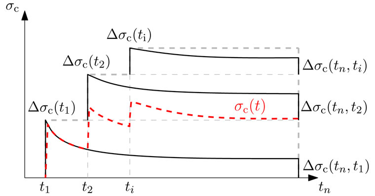
Figure 1. Schematic illustration of determination of total stress by superposition of initial stress increments and their accompanying viscoelastic effects.
On the other hand viscoelasticity of hardening concrete is very strongly time based. It mainly depends on concrete age at point of stress built-up and on duration of the effect. Both were very differently for all initial stress increments occurring in the hardening period of a concrete member—and their consideration by modification of Ec require very much expertise. In detail the modification of Ec in a time step must allow the consideration of all former initiated viscoelastic effects in this time step. And this has to be considered on the base of this time steps deformation impacts, caused by hardening. And nevertheless, it is not possible to simulate viscoelastic effects without any deformation impacts.
In contrast, present research develops material models needing specific input parameters for any case.
Finally present approaches offer no general possibility for consideration of viscoelasticity in FEM analysis of restraint stress states in hardening concrete members. The calculation results must always be verified by measurement data.
2.2. Main Feature of the Presented Approach and Its Benefits to a Time Step Based Analysis
The main feature of the presented approach is its relation to the pure viscoelastic material behaviour as it is given in the codes. Depending on the real stresses in the system a viscoelastic potential will be formulated and given into the calculation model as an additional deformation impact. A modification of Ec is not required, so that there is no risk of falsifying the systems restraint degree. And because of the separate treatment of viscoelasticity, their effects can be considered over the complete period of investigation, even if there is no deformation impact.
Finally, this allows an a priori quantification of real stresses at every point and time—and makes studies on the influence of concrete mixture, concreting time or kind and duration of treatment already in the design phase possible. The result is a stress development at special points. And the comparison with the tensile strength development at this point allows an estimation of risk probability. Furthermore, the stress distribution in the cross section at the critical time can be evaluated. This gives important information for estimation of expected crack formation.
3. Time Step Based Material Model for Viscoelasticity of Hardening Concrete
The material model is based on the creep-function in [1]. This creep-function returns the creep deformation in relation to the elastic deformation with 28d-elastic modulus. Next to strength class of concrete and surrounding conditions, height and development speed of this creep coefficient depends mainly on the age of concrete at loading start and duration of loading. The result of this function is the development of the creep coefficient over time, respectively, the height of the creep coefficient in a defined time step—a so called creep coefficient increment.
Figure 2 shows those creep coefficient increments for C30/37 and time step length of 12 hours depending on the age of concrete at loading start (increments with same colour belong together).
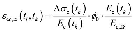
By means of this creep coefficient increments the viscoelastic effect of a stress change in a time step can be defined. Here it is important to scale the associated creep coefficient to the elastic modulus Ec(t) at loading start. The total viscoelastic potential of a former stress change can be estimated with:
 (2)
(2)
And the height of the viscoelastic impact in the actual time step amounts:
 (3)
(3)
This viscoelastic potential will be given into the related time step as a deformation load. The system re-
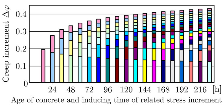
Figure 2. Creep behaviour of successive stress change. Pictured are the creep coefficient increments for time step length of 12 hours depending on time of origination (increments with same colour belong together).
sponse (creep or/and relaxation) depends on restraint degree k. The correlation between creep and relaxation in partially restrained systems is given in [2].
In case of loading in the actual time step (increase of the total stress condition), every former stress change, which led into loading too, has got a viscoelastic potential and brings this into the actual time step as an impact.
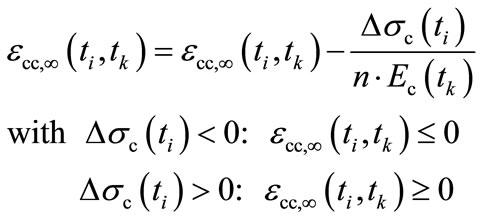
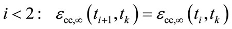
In case of unloading in the actual time step (relief of the total stress condition), the actual stress reduction minimizes only the total stress condition in the system but does not have a viscoelastic potential. In this context it has to be considered, that this stress reduction minimizes the viscoelastic potential of every former stress change. With n as number of former stress changes not equal to zero, a good approximation is provided by:
 (4)
(4)
This stress reduction can neutralize the viscoelastic potential of a stress increment. In that case, the possible residual value has to be distributed to the stress reduction of all remaining viscoelastic potentials.
In case of a total stress condition not equal to zero but no loading, the viscoelastic potential of the former stress changes reduces the total stress condition. And with this, the viscoelastic potential of every former stress change will be reduced. A good approximation is provided by:
 (5a)
(5a)
 (5b)
(5b)
In case of zero-crossing of the total stress state, it must be secured that no viscoelastic potential of former stress changes leads into new stress changes with opposite sign.
All these restrictions require a recording of the stress history of the system, an additional exploring calculation run for every time step and diverse distinctions.
This material model works only as an implementation in time step calculations. Because of dependences between total stress states and viscoelastic effects as well as the dependences between restraint degree of the actual time step and viscoelastic system response and outgoing from these interactions of stress states within the system, it is not permitted to use it as a post processing tool.
The implementation in FEM models takes place on the load side. It has to be done for every single element by on the fly analysis of the former calculation steps and database recording of the needed parameters. The usage requires the consideration of the existing element dimensions. In the first approximation, every element dimension gets an own viscoelastic behaviour in which element stresses are normative.
The following two examples exemplify the effect of the material model on the stress development of a completely restrained cube with temperature loads.
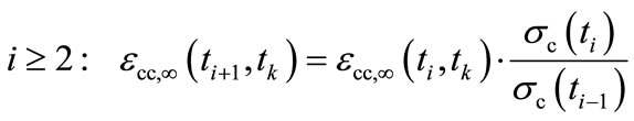
3.1. Example A: Abrupt Temperature Changing
The red solid line in Figure 3 shows the result for a completely restrained cube with abrupt temperature loads. They cause loading (a) and unloading with reduction of the viscoelastic potential of former stress changes (b). Between them there are periods with viscoelastic behaveiour without temperature load changing (tv). Additionally there is a period without any stresses after unloading at day 4. This period is created with a proper temperature change to demonstrate, that no zero-crossing occurs if the total stress state is equal to zero again. The grey dashed line pictures the development of total stress condition, if there is no further temperature change at the last temperature load point. For comparison of the influence of loading time, the black dash dotted line shows the development of total stress state in case of first loading at last load point.
The influence of the restraint degree is shown in Figure 4 by comparision with the calculation results of a partially restrained cube.
3.2. Example B: Adiabatic Heating
Figure 5 shows stress response to temperature changings according to the adiabatic heating. This exemplifies the effect of a continuous temperature changing under consideration of the evolution of stiffness. As it can easily be seen, the effect of viscoelasticity on the total height is reduced considerably. Another effect is the influence of the restraint
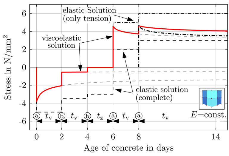
Figure 3. Stress development in a completely restrained cube with several abrupt temperature changes (Example A).
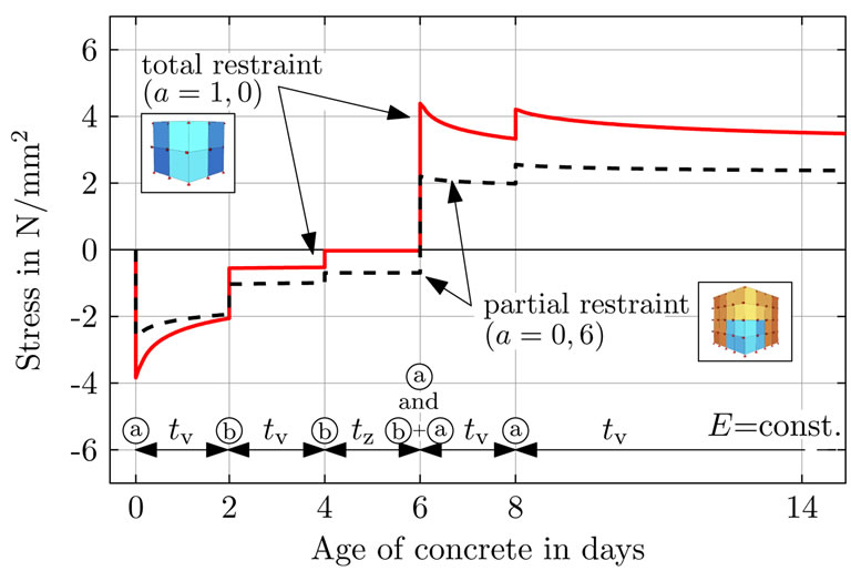
Figure 4. Influence of restraint degree on total stress quantity in Example A.
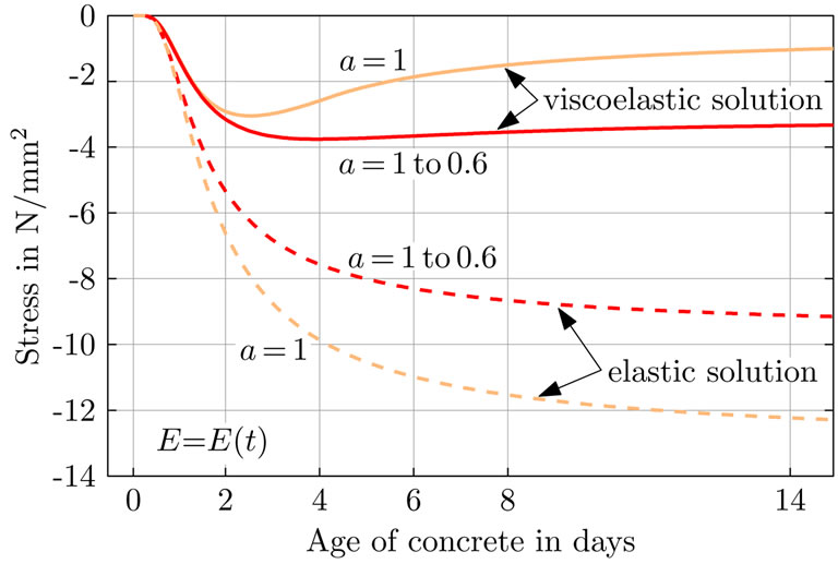
Figure 5. Stress development following to adiabatic heating with consideration of evolution of stiffness (Example B).
degree, which leads into less stress reduction in time.
4. Application Example: Power Plant Slab
The presented approach was used for the analysis of the hardening caused restraint stresses in the base slab of the power plant Boxberg [3]. For this a comprehensive monitoring program with in-situ measurements was carried and recalculated with a 3D FEM calculation model.
On one hand, the theoretical background of the presented approach was used to carry out a compatibility check of the measurement data. On the other hand, the presented approach was used in the 3D FEM simulation for recalculation of the measurement results. In both cases sufficient accordance could be achieved. At this point it should be pointed out, that the FEM simulation works as an a priori calculation without any back coupling to the measurement data.
4.1. Measurement Data and Compatibility Check
This monitoring program is based on a closed measurement system recording temperatures, stress and strain in comparable points. By a time discrete compatibility check of those three state variables in the concrete, the reliability of the data can be verified. Further details are given in [2,4].
The used measurement instruments are shown in Figure 6 and the results are given in Figure 7.
4.2. Comparison of Measurement Data with Results of FEM Simulation
Figure 8 gives an overview of the investigated construction stage of the slab and the localization of the viewed points. Additionally the temperature distribution at maximum member temperature is pictured.
Figure 9 shows the calculation model and gives detailed information on the assumptions and the conditions.
Figure 10 shows the results of FEM simulation in comparison with the measurement data for the marked points. Under consideration of many influence parameters on the hardening concrete slab, sufficient accordance with the measurement results could be achieved. Material parameters and details of the modelling of temperature development as well as evolution of stiffness were given in [3] and [4].
The new feature of this model is the consideration of viscoelastic effects by additional deformation impacts according to the viscoelastic potential of every time steps
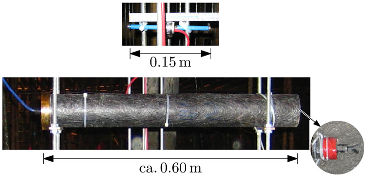
Figure 6. Measurement instruments, above: vibrating wire strain gauge, below: stressmeter.
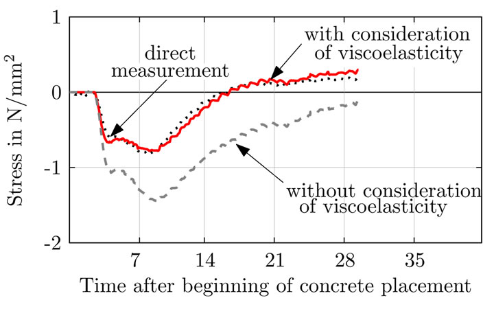
Figure 7. Compatibility check of the measurement data by comparison of direct stress measurement with calculated stresses based on strain data.

Figure 8. Viewed construction stage of the slab and localisation of the viewed points as well as temperature distribution at maximum member temperature.
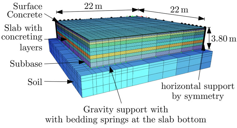
Figure 9. 3D FEM calculation model.
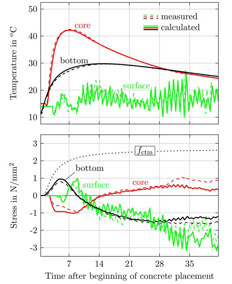
Figure 10. FEM simulation results and comparison with measurement data, above: temperature; below: stress.
stress increment. This material model is implemented for each element and works individual.
5. Conclusion and Outlook
In summary, the following issues should be pointed out:
1) Due to hydration heat, high temperature gradients occur in thick concrete members. Critical stress states can be achieved and crack formation is likely.
2) Accompanying stresses are dependent on development of stiffness, viscoelastic effects of the concrete and constraint.
3) 3D-Finite element analyses of thermal restraint give sufficient results, but not all material models are mechanically based and applicable in general.
4) Present approaches for consideration of viscoelasticity in restraint analysis of hardening concrete must be treated with caution.
a) In case of stiffness modification, the results can be falsified by influencing the restraint degree of system in an unrealistic way. Moreover, it is not possible with this modification to consider viscoelastic effects during the whole period of analysis.
b) In case of usage of material models with specific input parameters for every use case, no generally valid analysis method is provided.
5) The consideration of viscoelastic effects of hardening concrete in FEM analysis by implementation of additional deformation impacts according to the viscoelastic potential of the system provides a mechanically based material model, which can be used in general. The definition of the viscoelastic potential takes place on pure material behaviour and is not dependent on system properties. In this contribution, sufficient results could be achieved with definition of viscoelastic potential on the base of the creep-functions of [1].
6) The practicability of the suggested approach is given by the formulation as an impact based material model, which can be implemented parallel to the load matrix.
7) The suggested approach is generally admitted and not restricted to temperature loads and hardening concrete. It can be used for structure analysis in the state of use as well. This might be beneficial for the analysis of changing load states or the superposition of loads with temperature restraint.
It can thus be concluded that consideration of viscoelastic effects in FEM restraint analysis of hardening concrete is possible and can be carried out mechanically based. This provides meaningful information for the design of concrete mixture, required minimum reinforcement and curing methods, especially in case of thick concrete members. In addition, frequently asked question to real structural behaviour and phenomenon’s of concrete members can be answered by investigations—and not only with experience. As a positive side effect, this might strength the cooperation of concrete technologists, structural designers and construction companies.
At the moment, an all-embracing experiment set up is prepared at the Institute of Structural Concrete of Graz University of Technology, focusing on the development of the restraint force in hardening concrete.
In detail, this will be used for the verification of the introduced approach under laboratory conditions. In this course, the influence of curing method and duration on the height of restraint impact can be clarified.
Furthermore, the set up of this test frame allows the investigation of the superposition of early restraint due to hydration heat with restraint impacts of the state of use. Additionally, investigation on decrease of restraint force depending on type of cracking can be carried out as well.
6. Acknowledgements
Research of the authors was funded by Austrian Science Fund (FWF): I818-N24.
REFERENCES
- EN 1992-1-1: Eurocode 2: Design of Concrete Structures, Part 1-1: General Rules and Rules for Buildings, 2011.
- L. Nietner, D. Schlicke and N. V. Tue, Betonund Stahlbetonbau, Vol. 106, 2011, pp. 169-177. http://dx.doi.org/10.1002/best.201000051
- N. V. Tue, D. Schlicke and H. Schneider, Bautechnik, Vol. 86, 2009, pp. 142-149. http://dx.doi.org/10.1002/bate.200910013
- D. Schlicke and N. V. Tue, Measurement of Thermal ReStraint in Hardening Mass Concrete—A New Approach Exemplified by a Thick Foundation Slab. In Concrete Structures for Challenging Times, pp. 179-184. Marianske Lazne 2010, 6th Central European Congress on Concrete Engineering.