Wireless Engineering and Technology
Vol.3 No.2(2012), Article ID:18925,4 pages DOI:10.4236/wet.2012.32009
Software Defined Radio Prototyping with Visual C++ Express and Code Composer Studio
![]()
Nordic Semiconductor ASA, Trondheim, Norway.
Email: wichlund@gmail.com
Received February 23rd, 2012; revised March 16th, 2012; accepted March 31st, 2012
Keywords: SDR; OFDM; Waveform; IEEE802.11; DSK6713; Visual C++ Express; Baseband Processing
ABSTRACT
The primary goal of this project was educational: to demonstrate Software Defined Radio based prototyping using Visual C++ Express and Code Composer Studio. More specifically an IEEE802.11a Phy [1] compliant baseband processor was written in C++ and a radio link demonstrated “live” using a standard PCand the DSK6713 kit from Spectrum Digital [2] for baseband processing at the receiver and transmitter side respectively. To reduce costs without loss of educational value (the algorithms remains the same), the bandwidth was scaled down from 20MHz to 6 kHz to be able to utilize cheap narrowband COTS RF frontends operating at an intermediate frequency of only 12 kHz at the transmitter and receiver sides. This was easily achieved by just reducing the OFDM symbol rate by a suitable factor. The development process is described in detail, emphasizing development tricks to facilitate debugging of this kind of complex baseband processing. For educational purposes some other simpler waveforms was implemented as well.
1. Introduction
For the last two decades or so, SDR (Software Defined Radio) has been subject to tremendous research1. Fueled by the enormous semiconductor advancement, SDR technology is today at the core of established techniques like Cognitive Radio and DSA (Dynamic Spectrum Access) for more effective use of limited spectrum resources. From a stronghold within military applications, SDR technology is migrating into other application domains as well. There are many definitions of SDR, common is that the waveform is completely defined in software. A typical SDR architecture is depicted in Figure 1. Note that the up/down mixing can in general be either direct conversion or to/from some suitable intermediate frequency.
In this project we wanted to focus on the educational part of SDR prototyping and basic wireless communication concepts. Therefore, focus has been on low cost and writing the baseband processing software from scratch. Unless otherwise stated, we did not emphasize optimizing the code for reduced footprint. In a wideband and/or power constrained context this must of course be focused on. In summary the prime motivating factors were:
Ÿ Gain experience with implementing and debugging digital signal processing software using the free Visual C++ Express [3].
Ÿ Studying carrier and symbol timing recovery techniques applicable to IEEE802.11a/g.
Ÿ Getting a proper understanding of OFDM (Orthogonal Frequency Division Multiplexing) as well as improving skills with digital modulation and demodulation, filtering and pulseshaping.
There is a myriad of existing SDR development platforms out there that vary in cost and performance, from high-bandwidth systems requiring expensive development software to tiny less flexible systems with modest capabilities. The systems may be classified along different dimensions, e.g. cost, bandwidth, processing capabilities, type of RF frontend, development software, flexibility. A detailed overview is considered beyond the scope of this paper. An interesting taxonomy may be found in [5]. Some examples of available systems for SDR prototyping in order of decreasing cost:
Ÿ The “flexComm” SDR platform from Spectrum Signal Processing [6]. This is a high performance / high bandwidth platform.
Ÿ SDR development platforms from Lyrtech [7]. These are commercial high-performance/flexible systems requiring relatively expensive development soft-ware.
Ÿ The Typhoon SDR Waveform Development platform from Datasoft [8]. Interesting is that the popular GNU radio software [9] (a free toolkit for SDR development)

Figure 1. Common SDR architecture.
is supported by this platform.
Ÿ GNU radio [9] is often used together with the USRP device from Ettus Research [10]. This is a popular platform providing the base for several other systems as well [5].
However, either existing systems didn’t fit our budget or we found the flexibility to be insufficient. In addition, taking the educational value into account, we set out defining and developing our own. We may highlight the characteristics for our platforms follows in the order of decreasing priority:
Ÿ Low cost (uses relatively cheap hardware and mainly free software).
Ÿ Developed for educational purposes.
Ÿ Flexible, developed entirely in C++.
Ÿ Any RF frontend with an IF (Intermediate Frequency) in the vicinity of 12 kHz may be used.
The C++ language was chosen as the implementation language because it is “always” used within the digital signal processing community for programming DSPs (Digital Signal Processors). Although GNU radio uses a Phyton based programming interface, the core signal processing blocks are written in C++. Furthermore, every programmer has some C/C++ knowledge.
2. Architecture
Our hardware setup for the SDR platforms is shown in Figure 2. We utilize two PCs together with relatively cheap RF frontend hardware. On the transmitter side we implemented the baseband processor on a DSP using the DSK6713 from [2] connected to PC-A. The reason for this was twofold: 1) to gain experience in programming a DSP, and 2) to be able to compare TIs CCS (Code Composer Studio) IDE2 with Visual C++ Express for developing signal processing software. The DSK6713 has a CODEC that we connected to a mixer from [11] up-converting (without image rejection) our 12 kHz IF signal to 10.724 MHz. This mixer was chosen due to its excellent linearity; note that the crest factor3 for an IEEE802.11a signal is approx. 11 dB. We had a WRG313 receiver [12] from an earlier project and decided to reuse this as the RF frontend at the receiver side. This receiver has its own DSP for demodulation, however the DSP was bypassed and the IF samples were transferred directly to PC-B for demodulation on the PC itself. Note that Win
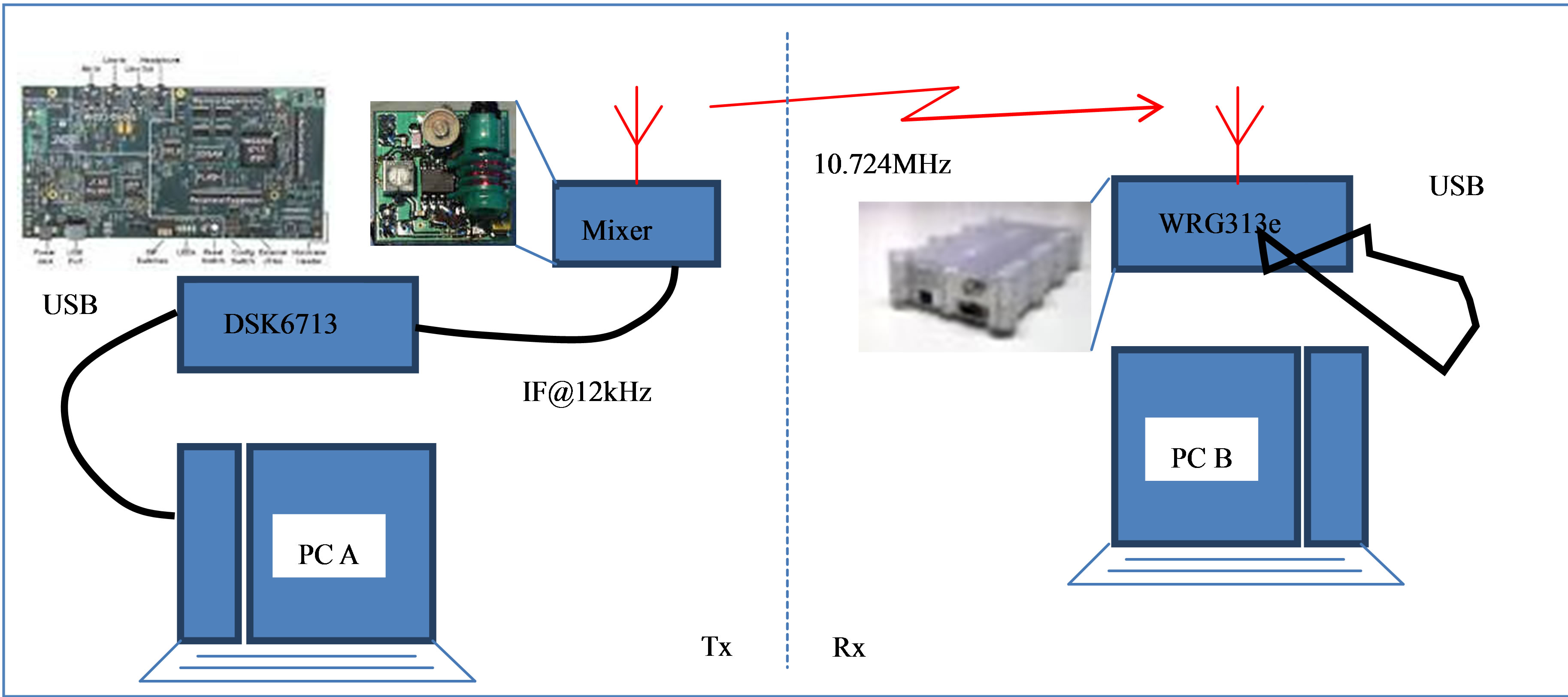
Figure 2. Our SDR platform hardware setup for the radio link.
Radio [12] provides an open API that facilitated complete control over the radio from our software developed on PC-B using Visual C++ Express.
To be able to prototype and run the complete IEEE802.11a baseband processing software using this radio HW setup, we had to scale down the 20MHz bandwidth in the standard [1] down to a manageable bandwidth, in this case 6 kHz. This was accomplished by scaling every relevant IEEE802.11a parameter in [1] by 3 × 10–4. The key figures are shown in Table 1.
The main blocks in an IEEE802.11a OFDM transmitter and receiver (physical layer) is shown in Figure 3.
We will not go into the OFDM fundamentals here, see e.g. [13]. In summary, at the top we have the transmitter chain consisting of inner (convolutional) coder, block interleaving (frequency domain spreading of adjacent bits) and sub-carrier mapping, IFFT transforming the complex OFDM symbol to time-domain samples, guardinterval (cyclic-prefix) insertion, pulse shaping and finally up-conversion to RF. In our case, all these blocks were implemented in C++ using CCS and the executable then downloaded to the DSK6713 board. The up-conversion to “RF” was done using the mixer mentioned above, converting the 12 kHz IF signal output from the onboard DSK6713 CODEC to a 10.724MHz signal radiated from a random wire a few feet long. See Figure 2.
On the receiver side we have down-conversion from RF to a complex baseband signal. In general this may be done either directly or via one or more intermediate frequencies. The choice is left to the implementer. Each method has its strength and weaknesses and the relatively complex trade-offs here are beyond the scope of this paper, see e.g. [14]. In our case we used the WRG313e receiver for converting the received 10.724 MHz signal down to a 12 kHz IF signal at 48Ksamples/s which was then transferred to PC-B via the USB cable.
Please observe that in our low-cost (narrowband) setup, common issues like I/Q mismatch and DC offset are non-existent because the actual I/Q merge/split is done digitally (in the software) with only real IF signals involved. In a system operating at the rated speed and RF frequencies [1], the (broadband) RF frontend will typically be more similar to that in Figure 1 and these issues must of course be dealt with to adequately fulfill required radio performance parameters4.
Following the complex down-conversion is channel filtering (ensuring proper selectivity) and down-sampling to reduce the computational burden in the downstream
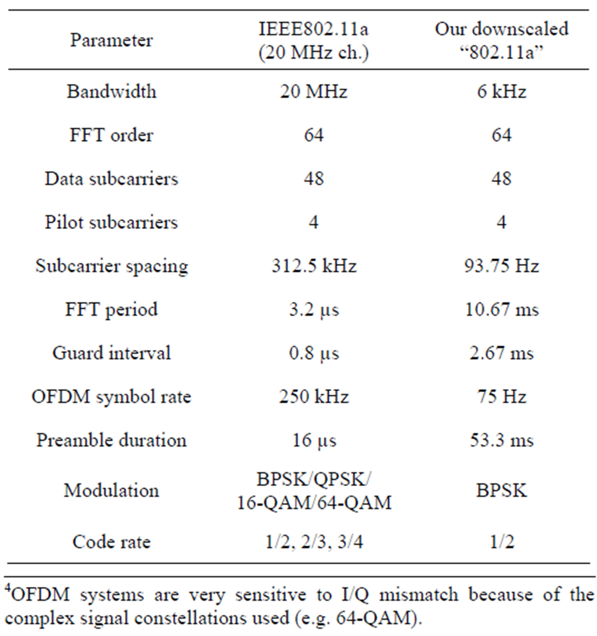
Table 1. IEEE802.11a parameters vs. downscaled “802.11a”.
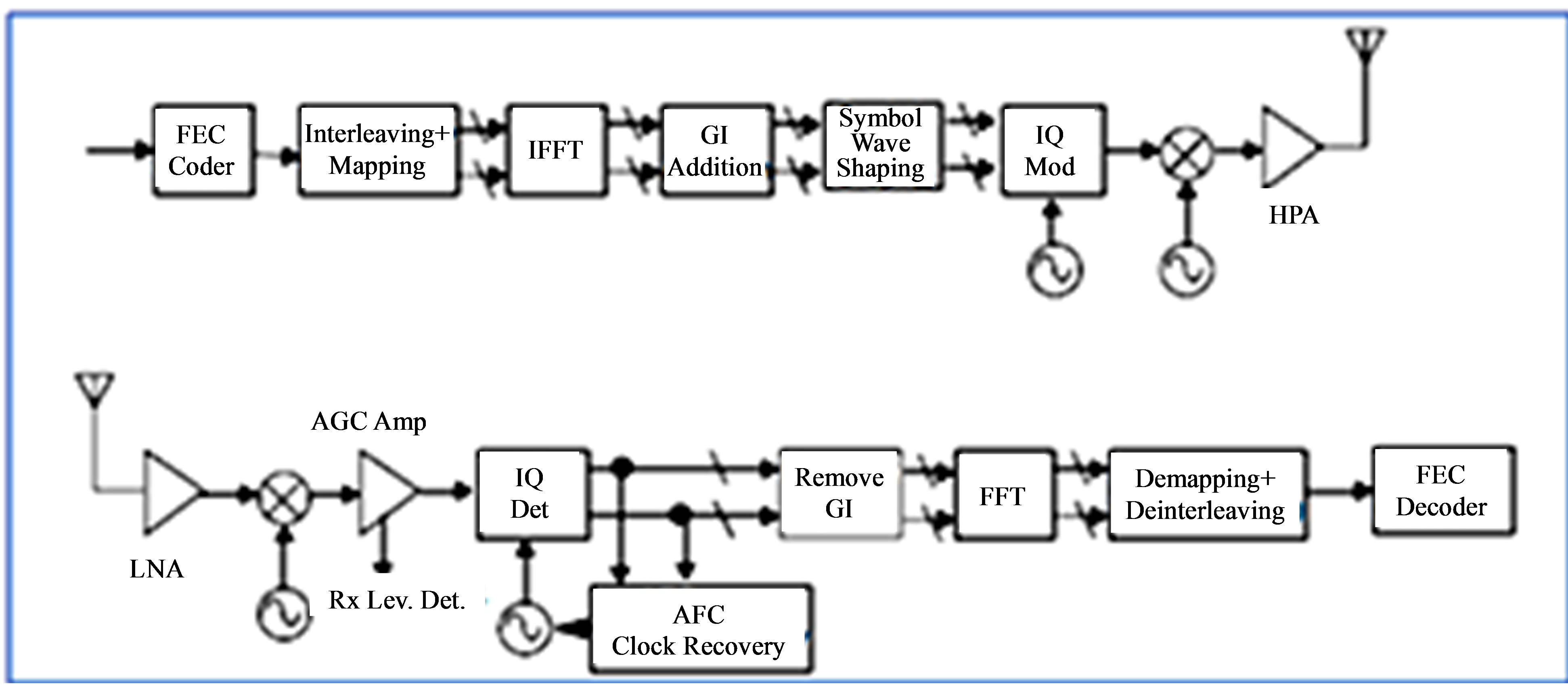
Figure 3. Transmitter and receiver block diagram for an IEEE802.11a OFDM Phy [1].
signal processing blocks. This is not shown in Figure 3. Then come a vital block, namely the carrier and timing recovery engine (synchronizer). The task of this block is to estimate the carrier frequency/phase offset and symbol clock from the incoming signal. In a communication system it is of vital importance that this block is carefully designed as its performance will directly affect the packet error rate for a given demodulator SNR. Assuming that carrier, symbol timing and frame synchronization5 have been performed, the guard-interval is removed and FFT is performed to enable individual subcarrier demodulation. After subcarrier demodulation and equalization6, the raw bits are de-interleaved and passed on to a Viterbi decoder. The bits output from this decoder are then fed to the next protocol level for processing.
3. The Development Phase
Being faced with such a complex development task, we started out with modeling the whole system in Octave [15]. The role of this system modeling can be summarized as follows:
Ÿ First, to get a proper understanding of the OFDMmodulation principles, experimenting with different system parameters, before implementing. See also the tutorial paper [13].
Ÿ Algorithm development: although the key blocks in the processing chain are well defined (Figures 17-12 in [1]), it is left to the designer to choose and implement algorithms for carrier and timing recovery [16,17]. This is a research field on its own and beyond the scope of this paper. However, we will present our implementation of a proper7 carrier and timing synchronizer in detail below.
Ÿ To have a cycle-accurate reference model during the C++ implementation proved extremely useful throughout the development phase.
We started with generating the complex baseband samples constituting the training symbols, see Figure 4. These were verified against Annex G in [1].
We then went on with modeling all the blocks in Figure 3 except for the frontends (the connection in the model between Tx and Rx chains was the 12 kHz IF signal). The most complex blocks to model were the synchronizer and the Viterbi decoder. Since the model was going to be used as an implementation reference for the successive C/C++ implementation, we modeled these blocks in an elaborate way (cycle accurate) to make this transition as smooth as possible. It should however be mentioned that we skipped the “normal” floating-point to fixed-point model refinement during modeling8. For more details about the synchronizer, see appendix A.
Having the model up and running, we were set for the Tx software development on the DSK6713. Before going into further details, we summarize the hardware and
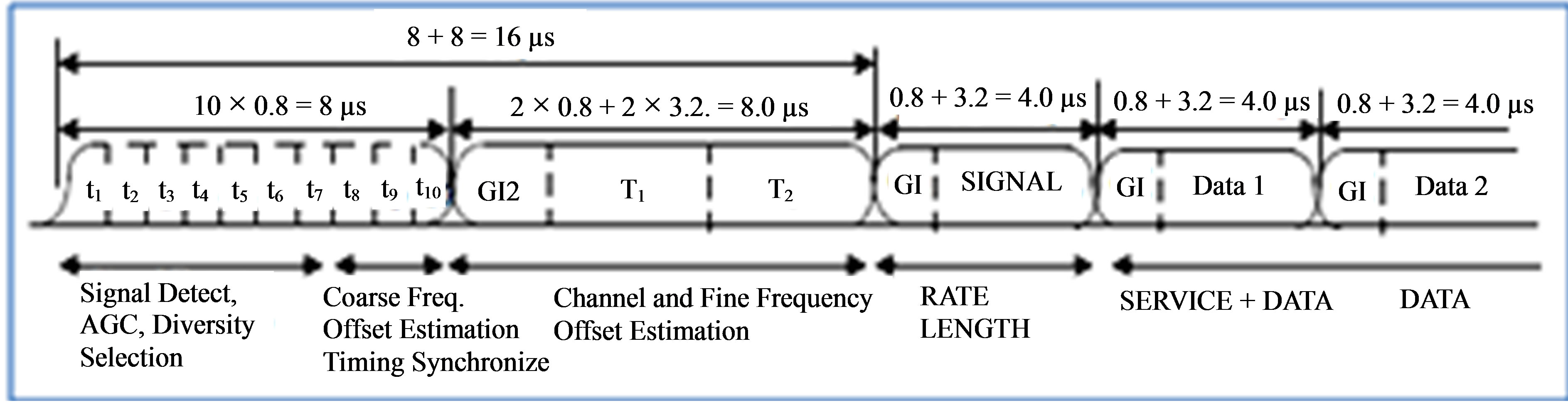
Figure 4. IEEE802.11a OFDM training symbols [1].
software used in Table 2.
Rather than developing the Tx software from scratch in CCS, we decided to implement this software first in VC++ on PC-B on the receiver side. See Figure 5. The reason for this was mainly twofold:
Ÿ This enabled us to dump samples to file from any “probe” point in the Tx software and successively verify the samples directly against our model by reading the samples file into Octave. In this way we were able to verify each development “step” in a direct way that wouldn’t be possible on the DSK6713.
Ÿ During the successive Rx software development we utilized the Tx software9 set up in software-loopback for verification. This proved very useful indeed.
Following the development of the Tx part of the software in VC++, we ported this software into a project denoted “OFDM” in CCS on PC-A. This was pretty straight forward. We verified this step by compiling and debugging the software on the DSK, comparing the generated baseband samples against Annex G in [1]. The sample rate was set to 48 kHz, thus an oversampling factor of 8 (the elementary sample rate is 6 kHz, see Table 1). The complex baseband samples were upsampled to 48 kHz using a FIR interpolation filter and then upconverted to real 12 kHz IF samples by multiplying the samples with  and keeping the real part. The samples were then scaled properly before being output to the CODEC on the DSK6713. A screen shot of the CCS GUI is shown in Figure 6. Furthermore, a scope picture of the final 10.724 MHz signal transmitted on-the-air is shown in Figure 7.
Before going into details about the Rx development, it should be emphasized that the author prior to this project had written a small application for interfacing to the WRG313 receiver using the G313API SDK. This application contains demodulators for simpler modes (AM, FM, SSB, RTTY, BPSK) and has a GUI based on the Qt SDK [18] and sound output10 based on the PortAudio API [19]. Thus it was not necessary to start from scratch establishing the various software “infrastructure” (GUI, lower level software interface to APIs) and it was thus possible to concentrate solely on the implementation of the core DSP algorithms in this project.
The class hierarchy for the VC++ “modem” project is depicted in Figure 5. The Tx part consists of the “Wavesynth” class and parts of “FEC” and “OFDM”. As mentioned above, this part of the software was ported to CCS on PC-A. The part of the software which is the scope of this work was partitioned into the following classes:
Ÿ “FEC”: encoding and decoding (Viterbi) according to the standard [1].
Ÿ “OFDM”: PLCP preamble generation (short and long training symbols), FFT/IFFT, interleaving, packet assembly, windowing.
Ÿ “OFDMRX”: implements Figure 8, in addition to subcarrier demodulation, equalization, de-interleaving, decoding.

Table 2. Software and hardware used during development.
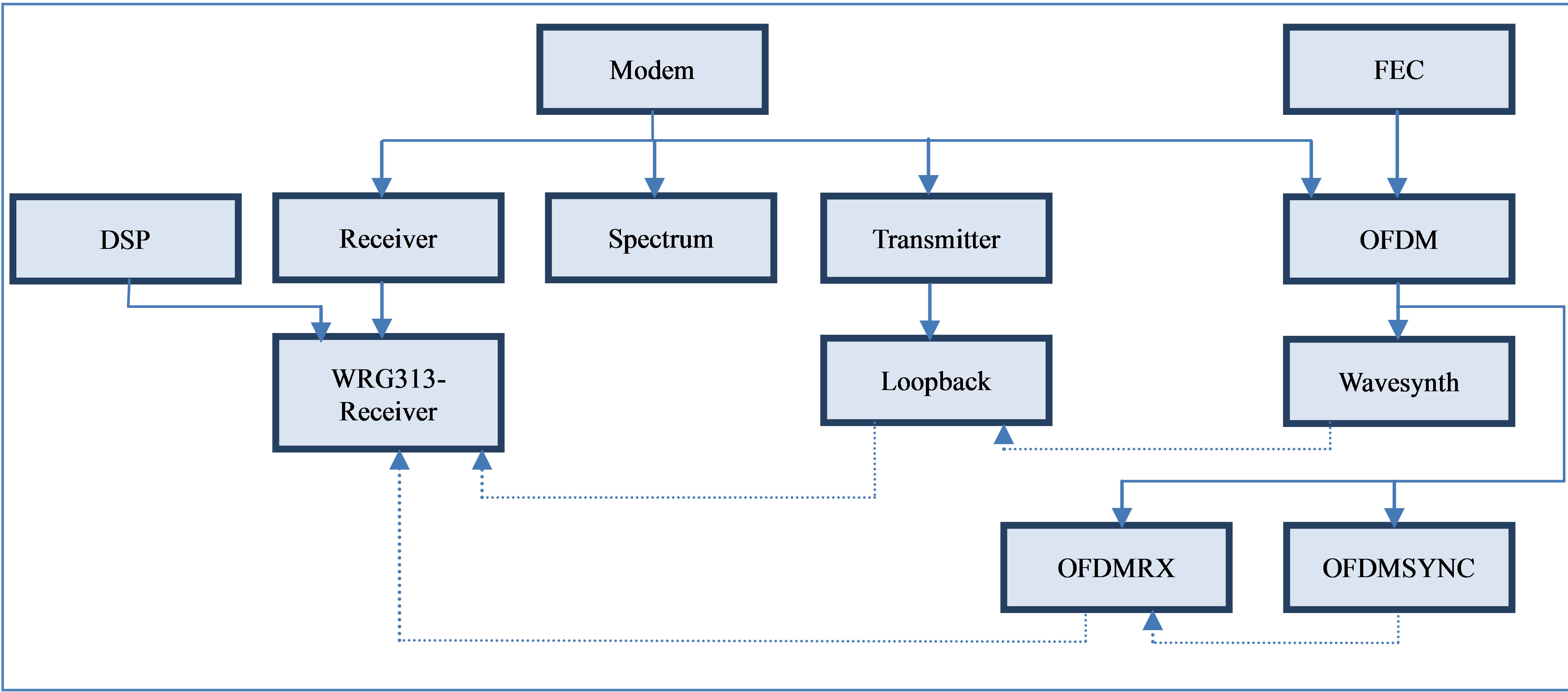
Figure 5. Class hierarchy for the VC++ “modem” project. Dashed lines denotes object instantiation, e.g. a “Loopback” object will instantiate one “Wavesynth” object.
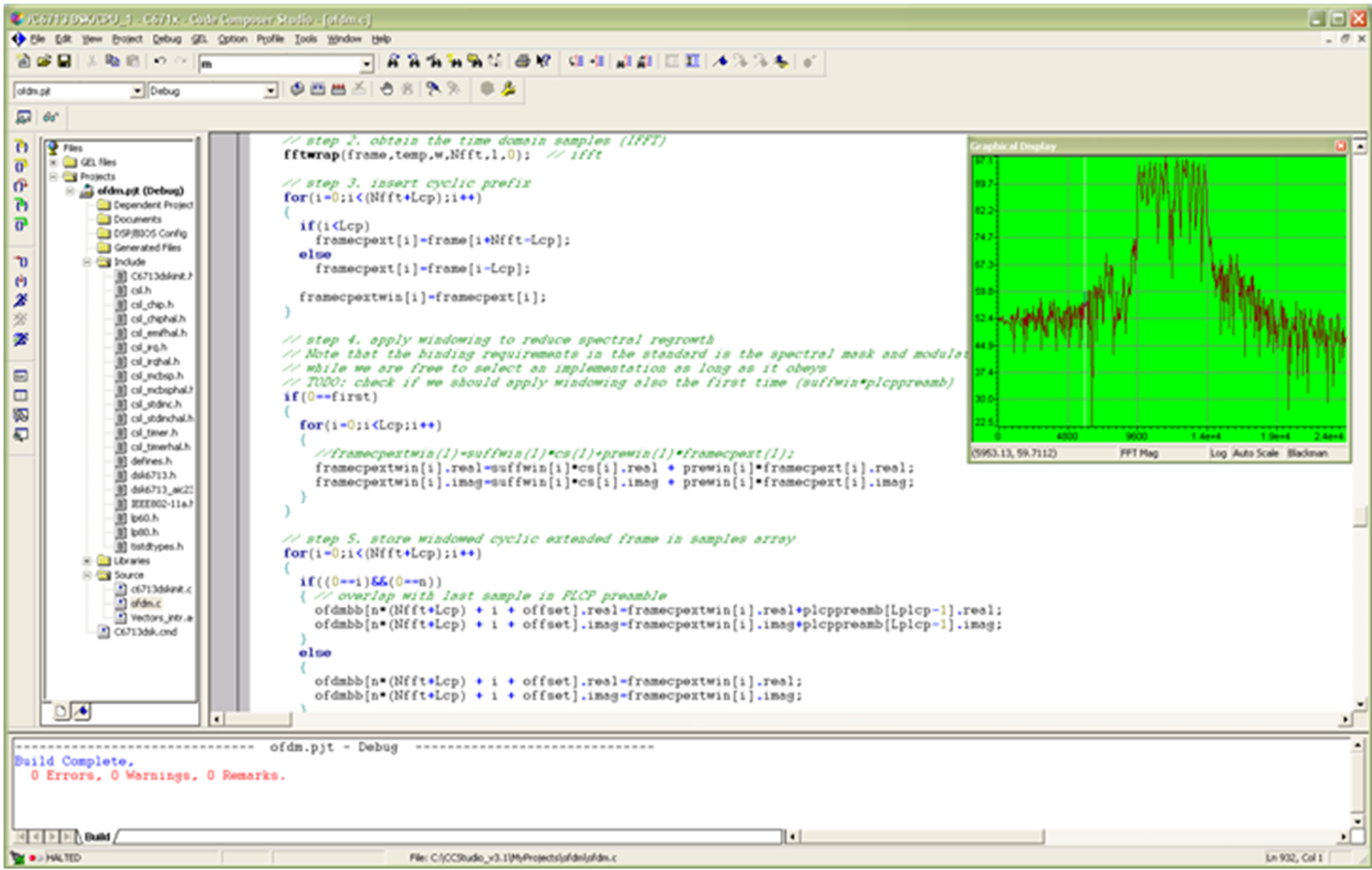
Figure 6. Screen shot of the Code Composer Studio GUI with our “OFDM” project open. An FFT of the transmitted 12 kHz IF signal is shown at the upper right corner of the screen.
Ÿ “OFDMSYNC”: implements the synchronization (carrier and timing recovery, pilot based residual frequency offset correction). See “synchronizer” in Figure 8 as well as Appendix A.
We started the Rx software development by implementing the “synchronizer” (class “OFDMSYNC”) which has been described in detail in Appendix A. With the Tx part of the software now in place in the VC++ project, it was very convenient during debug to loopback Tx to the Rx part of the software under development. Thus the Tx

Figure 7. Oscilloscope screen shot of the 10.724 MHz signal. Note that the image of the signal is visible at the left, since the image is not rejected.
part in loopback acted effectively as our Rx testbench. Alternatively we could have read in reference samples from the Octave model, but as mentioned earlier it was beneficial to develop the Tx software itself within the same VC++ project on PC-B.
To increase confidence, we implemented incrementally in small steps. Thus, the “testbench” for each step consisted of:
Ÿ Stimuli generation by the previous block(s) in the Rx processing chain.
Ÿ Verifying the response by dumping the samples to file and reading them into our Octave model for verification.
Only after gaining sufficient confidence in the current implementation, we did move on to the next step in the processing chain.
Implementing OFDMRX was relatively straightforward due to the “processing blocks” being so well defined by the standard [1]. However when implementing the Viterbi decoder (belongs to class “FEC”), the tutorial [20] was of great help. Much of the total debugging time was spent on this decoder. A screenshot of VC++ with the “modem” project during debugging of the Viterbi decoder is shown in Figure 9.
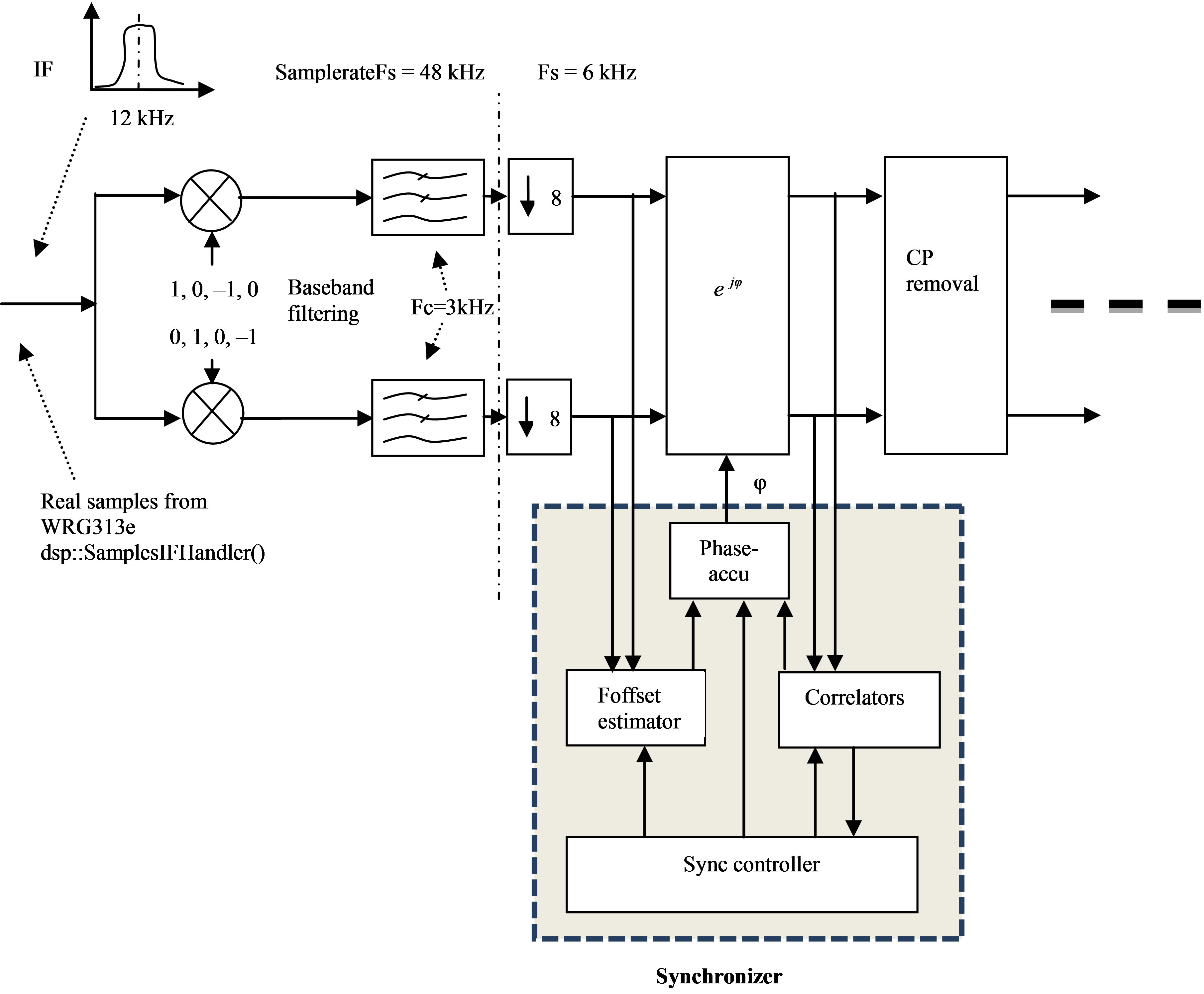
Figure 8. A detailed view of parts of the receiver chain, including the synchronizer. All blocks shown modeled in Octave and implemented in C++.
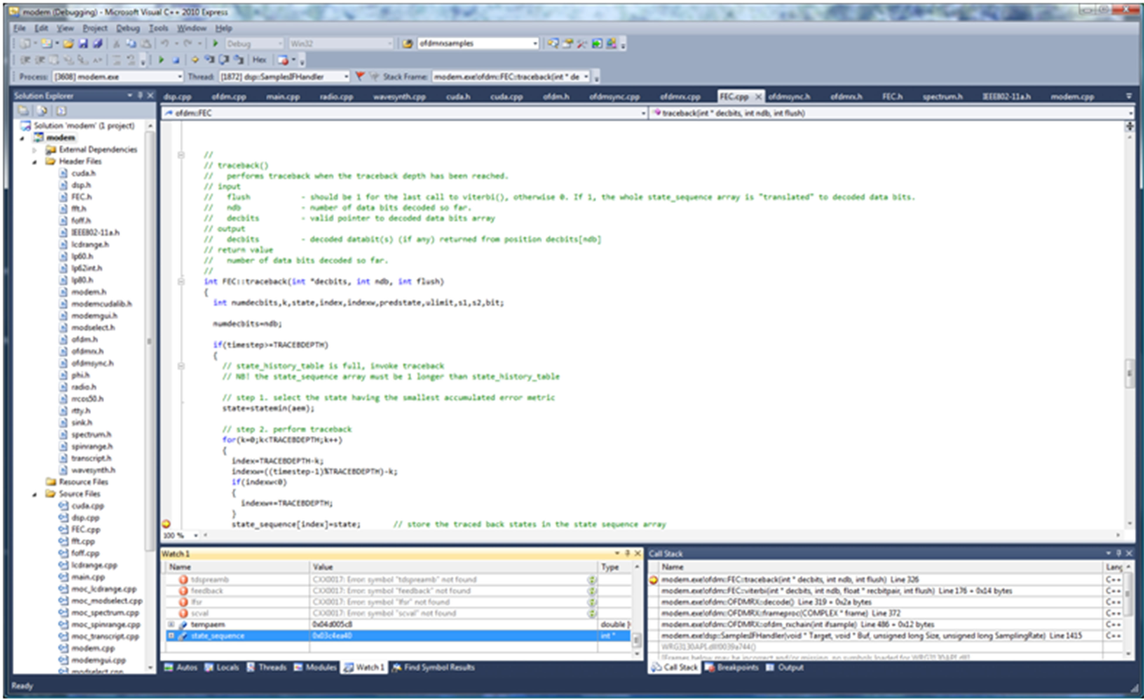
Figure 9. Screen shot of Visual C++ 2010 Express GUI with our “modem” project open.
To be able to effectively use the Octave model as a reference, we used the same LFSR (Linear Feedback Shift Register) for payload generation in the Tx software and the Octave model.
4. Results
A GUI screenshot of our application running on PC-B is shown in Figure 10. The main part of the GUI consists of a real time spectrum display of the 12 kHz IF as received from the WRG313 radio. At the bottom is a transcript window logging packet statistics. To ensure adequate SNR we located the transmitter and receiver as shown in Figure 2 within a few meters of each other.
For reference, we started testing with FEC disabled and achieved a PER (Packet Error Rate) of approx. 30%. With FEC enabled the PER dropped to well below 1%. The packet length was fixed at 10 OFDM symbols (including the SIGNAL field, excluding the PLCP preamble).
For such a narrow bandwidth, the processing requirements were modest. On the Rx side, the “modem” project’s CPU usage on PC-B was barely noticeable. On the Tx side, we were well within limits set by the sample rate (48 kHz). However, we struggled a bit with the memory footprint; some minor tweaking was necessary to fit the executable within the 264 kB L1/L2 memory of TMS320C6713.
A direct comparison of VC++ Express and TIs CCS with respect to DSP software development may be difficult based on one project only. However, here are a couple of observations based on our setup.
CCS has better data analysis (graph plotting frequency/time domain) possibilities, but this was partly outweighed in our project through the use of Octave together with VC++. Implementing the DSP software this way, using VC++ in tandem with Octave turned out to be surprisingly effective in this project. Another observation is that the “Express” version of VC++ has no profiling support. In addition to extensive profiling support, CCS has other useful analysis capabilities facilitating real time embedded software development.
We found that it was quite convenient to partition the Rx software as discussed earlier: during debug it was e.g. possible to “watch” the whole OFDMSYNC object, thus tracking “key” sync parameters during packet receive.
Approximate software development times are depicted in Table 3.
The development times listed are based on the number of SVN commits with an average of 4 man hours per commit. The development time of the existing software “infrastructure” (the GUI, etc) is not included here.
5. Conclusions and Further Work
In this work we have demonstrated the high level modeling and subsequent SDR implementation of an IEEE802.11a
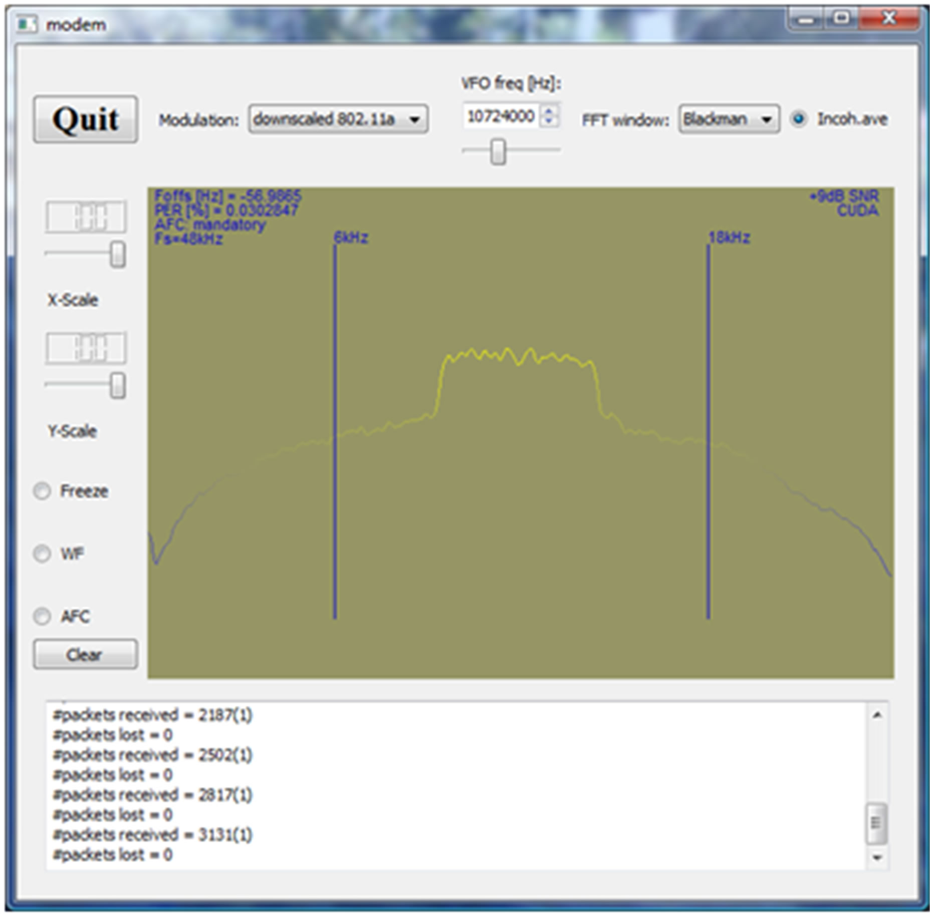
Figure 10. Screen shot of the “modem” GUI. An FFT of the received 12 kHz IF signal is shown in the middle. The transcript window at the bottom shows the received packet statistics. Note that the carrier frequency offset displayed at top left is the offset as estimated prior to offset correction (i.e. it is not the residual offset).
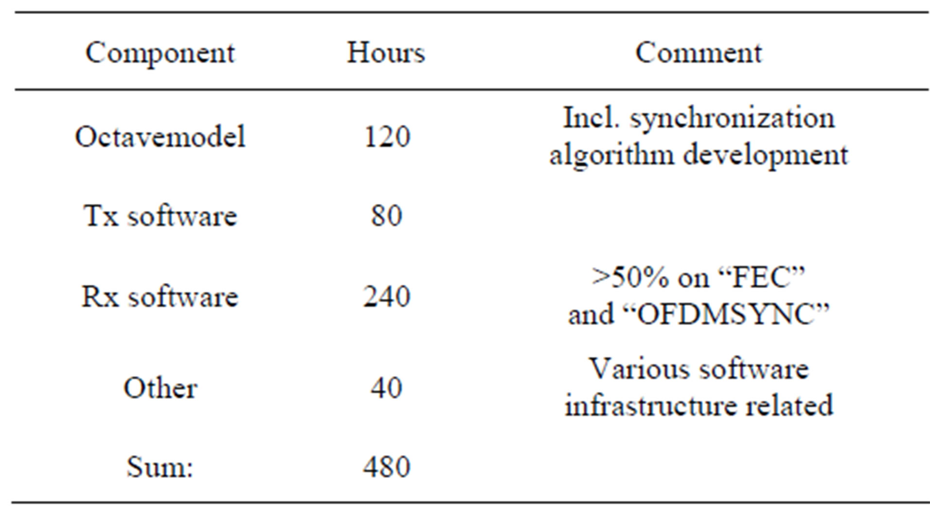
Table 3. Approximate development time spent on Octave modeling and C++ implementation.
Phy compliant baseband processor. The baseband processor was implemented in C++ using MS’ VC++ Express and TIs CCS and executed on a standard PC as well as on the DSK6713 board. To be able to demonstrate functionality utilizing relatively cheap RF frontends, the bandwidth was scaled down to 6 kHz without loss of educational value.
We believe we could have put together a similar system running in the 2.4/5 GHz band in a shorter time frame using commercially available prototyping platforms with available reference designs and more sophisticated development tools. But the cost would have been on a completely different scale. Our focus has been on low cost and educational value using only free tools as far as possible.
At a later stage it would have been interesting to investigate the possibility of porting some of the developed C++ code to fit one of the available USRP RF frontends from Ettus [10]. Other platforms don’t fit our low cost budget.
REFERENCES
- http://standards.ieee.org/findstds/interps/802.11-2007.html
- Spectrum Digital Inc. www.spectrumdigital.com
- The free Visual Studio 2010 products. http://www.microsoft.com/visualstudio/en-us/products/2010-editions/express
- J. Mitola, “The Software Radio,” Proceedings of IEEE National Telesystems Conference, 19-20 May 1992, Washington DC, pp. 13-15.
- Christophe F4DAN. http://f4dan.free.fr/sdr_eng.html
- Spectrum Signal Processing. www.spectumsignal.com
- Lyrtech. http://www.lyrtech.com.
- Datasoft. www.datasoft.com
- GNU radio. www.gnuradio.org
- Ettus Research. www.ettus.com
- SAT-Service Schneider. http://www.sat-schneider.de/DRM/DRM.htm
- WiNRADiO Communications. http://www.winradio.com/home/g313e.htm
- S. A. Fechtel, “OFDM: From the Idea to Implementation,” Advances in Radio Science, Vol. 3, 2005, pp. 27-37. doi:10.5194/ars-3-27-2005
- P. Kenington, “RF and Baseband Techniques for Software Defined Rario,” Artech House, London and Boston, 2005.
- Octave. http://www.gnu.org/software/octave/download.html
- H. Meyr, M. Moeneclaey and S. A. Fechtel, “Digital Communication Receivers,” John Wiley & Sons Inc., Hoboken, 1998.
- C.-H. Liu, “On the Design of Symbol Timing Recovery for WLAN OFDM Systems,” IEEE 8th International Symposium on Spread Spectrum Techniques and Applications, Sydney, 30 August-2 September 2004, pp. 184-188.
- Qt SDK. qt.nokia.com
- PortAudio Cross-Platform API. www.portaudio.com
- Viterbi Decoding Tutorial. http://home.netcom.com/~chip.f/viterbi/tutorial.html
- Wang, “Design and Implementation of Timing Acquisition in IEEE 802.11a Wireless LANs,” Proceedings of the 2003 Joint Conference of the 4th International Conference on Information, Communications and Signal Processing, Singapore City, 15-18 December 2003, pp. 554- 558.
Appendix: The Synchronization Engine
The location of the synchronizer is shown in more detail in Figure 8. The figure shows the first parts of the receiver chain. Note that the synchronizer is running at the (elementary) sample rate of 6 kHz. The block labeled “Foffset estimator” is providing a coarse estimate of the carrier frequency offset based on the short training symbols, see Figure 4. It must be run prior to timing recovery, otherwise the correlator based timing recovery algorithm will not provide qualifying correlation peaks. This will become clear below11. The coarse frequency offset estimator we chose here is based on Phase Increment Estimation [16]. Let 1)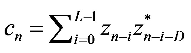 , z complex baseband samples Then we may estimate the carrier frequency offset by 2)
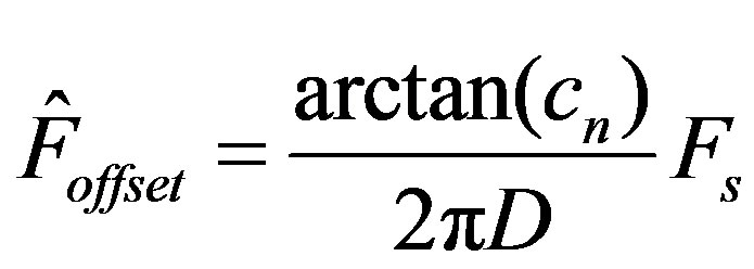
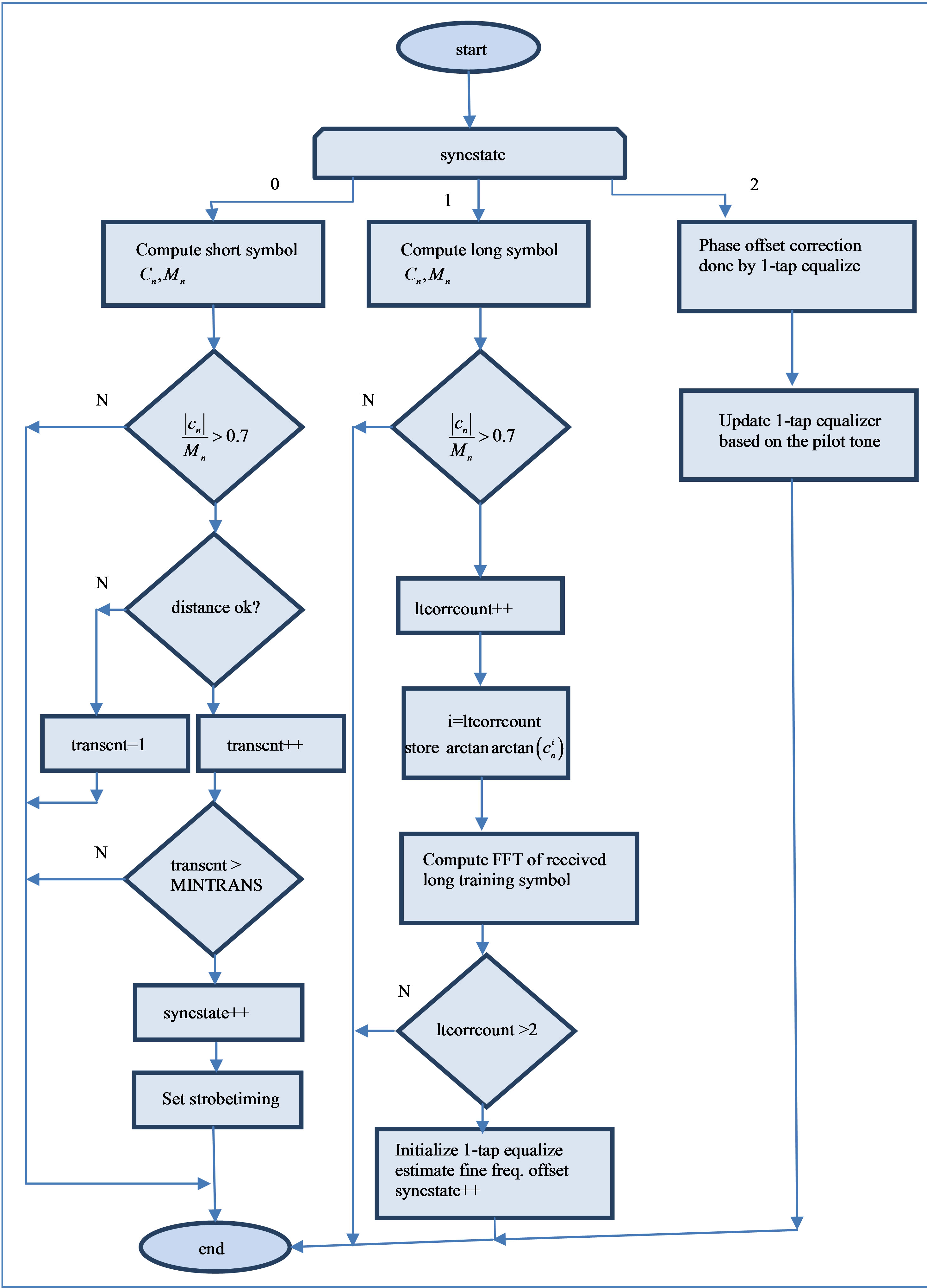
Figure 11. The “sync controller” state machine. Some details are not shown.
where  is the sampling rate (6 kHz here) and D is a constant. The choice of D is not trivial [16,21]. We chose a value of 16 to cancel the modulation effect on the estimate since the short training symbol length is 16 samples long given our sample rate. A correlation length L of 32 was found to be sufficient through experiments with our Octave model in an AWGN channel.
The increment in the phase accumulator in Figure 8 was then loaded with the initial (coarse) carrier frequency offset estimate given by Equation (2). This estimate must be “good” enough to allow subsequent timing synchronization.
The timing recovery is based on the correlation of the complex baseband samples with coefficients  constituting the short training symbol. Let 3)
 , z complex baseband samples 4)
The symbol timing was then recovered by monitoring the value of . A sufficient correlation (peak) was defined as
  . By counting a sufficient number of correlation peaks (4 in our case) occurring sequentially with a distance of 16 +/–1 sample between them, we then based our subsequent long symbol strobe timing on the average of the time of these events. The reference time was simply given by a modulo 16 counter.
The frame synchronization is based on the correlation of the complex baseband samples with coefficients  constituting the long training symbol:
5) , z complex baseband samples
6) 
Note the value 32 added to the index in the coefficients  in Equations (5)-(6). This was to avoid correlating with the samples constituting the cyclic prefix added to the first long training symbol, see Figure 4. In additionwe only had to evaluate
  at the recovered strobe timing. At the second event of
  we know that the subsequent OFDM symbol according to the standard [1] will be the SIGNAL symbol. We are now frame synchronized as well, and know that the subsequent OFDM symbol shall be processed 80 samples in time after the last event of
 . This reference time is ensured by a modulo 80 counter, initialized at this time.
We also used Equation (5) for fine frequency offset estimation. By storing the value of  after correlation with each of the two long training symbols, we then calculated the fine frequency offset estimation by:
7) 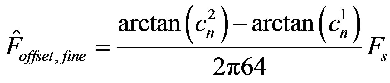
where  and
and  are
are  after correlation with the first and second long training symbol respectively. The increment in the phase accumulator in Figure 8 was then adjusted by adding the fine carrier frequency offset estimate given by Equation (7) to the increment.
The proper sequencing of the blocks and events in the synchronizer was orchestrated by the block labeled “Sync controller”. This is a state machine which runs continuously at Fs. The state of the synchronizer is given by the variable syncstate. The state machine is depicted in Figure 11 below.
Some details have been omitted in the figure. More specifically:
Ÿ A “watchdog” was implemented which resets the synchronizer in the case that the long training symbol correlator fails detection (missed framesync).
Ÿ The tasks in the figure corresponding to syncstate > 0 are run at a sample rate : The tasks corresponding to syncstate==1 are run@
 , while the tasks corresponding to syncstate==2 are run @
  (the OFDM symbol rate).
NOTES
1See the landmark paper by J. Mitola [4].
2Integrated Development Environment.
3Or peak-to-average power ratio is a dimensionless quantity calculated from the peak amplitude of the waveform divided by the RMS value of the waveform.
4OFDM systems are very sensitive to I/Q mismatch because of the complex signal constellations used (e.g. 64-QAM).
5Frame synchronization is the task of determining the relative bit position in the received data-packet such that we know where the header and payload starts. This task is easily done by correlating with a known pilot symbol.
6Not shown in Figure 2 is a necessary equalizer block which equalizes the channel effect on the OFDM symbol. The 1-tap equalizer coefficients are easily computed based on the long training symbol. They are successively updated based on the pilot symbols. Note that the subcarrier phase coherency is based on the complex rotation done by the equalizer.
7“Proper” in this case means that the synchronizer worked flawlessly (didn’t turn out to be a bottleneck with respect to packet error rate) under the conditions present in our experimental setup.
8This step is mandatory when designing DSP systems for HW implementation (ASIC, FPGA) to be able to estimate area/speed/power before going to HW. In our case however, the SDR implementation is largely floating point based since the TMS320C6713 on the DSK is a floating point DSP.
9Which now had been verified against our “golden” Octave reference model.
10Only relevant for the voice modes.
11Although powerful algorithms for joint frequency offset and timing recovery exist (see e.g. [16]), we chose to split these tasks here.