Smart Grid and Renewable Energy
Vol.08 No.10(2017), Article ID:80100,11 pages
10.4236/sgre.2017.810021
Effect of Incidence Angle of Magnetic Field on the Performance of a Polycrystalline Silicon Solar Cell under Multispectral Illumination
Idrissa Sourabié, Issa Zerbo, Martial Zoungrana, Dioari Ulrich Combari, Dieudonné Joseph Bathiebo
Laboratory of Thermal and Renewable Energies, Department of Physics, University Ouaga I Prof. Joseph ki-Zerbo, Ouagadougou, Burkina Faso

Copyright © 2017 by authors and Scientific Research Publishing Inc.
This work is licensed under the Creative Commons Attribution International License (CC BY 4.0).
http://creativecommons.org/licenses/by/4.0/


Received: September 18, 2017; Accepted: October 28, 2017; Published: October 31, 2017
ABSTRACT
The aim of this work is to investigate, with a three-dimensional steady-state approach, the effect of the incidence angle of a magnetic field on the performance of a polycrystalline silicon solar cell under multispectral illumination. The magneto-transport and continuity equations of excess minority carriers are solved to
find the expression of the density of excess minority carriers and the related electrical parameters, such as the photocurrent density, the photovoltage and the electric power, of a grain of the polycrystalline silicon solar cell. The influence of the incidence angle of the magnetic field on the diffusion coefficient, the short-circuit photocurrent density, the open-circuit photovoltage and the electric power-photovoltage is studied. Then, the curves of the electric power-photovoltage is used to find the maximum electric power allowing to calculate, according to the incidence angle of the magnetic field, the fill factor and the conversion efficiency. The study has shown that the increase of the incidence angle of the magnetic field from 0 rad to π/2 rad, can reduce the degradation of the performance of solar cells.
Keywords:
Bifacial, Conversion Efficiency, Incidence Angle, Magnetic Field, Polycrystalline Silicon Solar Cell

1. Introduction
The performance of photovoltaic modules and cells depends on climatic and seasonal parameters but also on external factors as electric field, magnetic field, or electromagnetic field.
Concerning the effect of climatic and seasonal parameters on the performance of photovoltaic modules, it has been proved that for PV cells/modules, the open circuit voltage decreases with an increase in the cells temperature but increases with an increase in solar radiation [1] [2] . As for the short-circuit, it increases with an increase in solar irradiation as well as an increase in temperature [1] [2] . Finally, the electrical efficiency and the power output of a PV module decrease with an increasing operating temperature of the PV cells/modules [3] . On the other hand, the maximum power produced by PV modules decreases under partially shaded conditions [4] [5] and when dust particles are deposited on them [6] .
Various researchers used both experimental and theoretical methods to study the effect of magnetic field on the properties of solar cells. Betser et al. [7] used an experimental method to measure the mobility of minority carriers in the base of InP/GaInAs heterojunction bipolar transistor under constant magnetic field. The magnetic field was applied perpendicular to the direction of the current flow or parallel to the surface of junction emitter-base of the HBT. Vardanyan et al. [8] proposed a method for measuring all recombination parameters (diffusion length, diffusion coefficient, carriers mobility, back surface recombination velocity) in the base region of bifacial solar cell illuminated by its rear side and under constant magnetic field applied parallel to the surface of the p-n junction. Others researchers Madougou et al. [9] , Zouma et al. [10] , Zerbo et al. [11] [12] , Sané et al. [13] , Zoungrana et al. [14] [15] and Combari et al. [16] , proposed studying the modelling of the negative effect of magnetic field on the performance of solar cells and photovoltaic modules. In their studies, the magnetic field was applied parallel to the surface of the p-n junction of the solar cells. In all these experimental and theoretical methods used to study the effect of magnetic field on the response of solar cells, the magnetic field was applied parallel to the surface of the p-n junction of the solar cells and it caused a degradation of the performance of solar cells.
As a magnetic field causes a degradation of the performance of solar cells, in this work, we showed how the increase of the incidence angle of a magnetic field can limited the degradation of the performance of a polycrystalline silicon solar cell in a three-dimensional steady-state approach.
2. Theoretical Background
The bifacial polycrystalline silicon solar cell n+-p-p+, studied, is modelled as a regular array of parallelepipedic grains connected in parallel [17] [18] . Each grain has the same electronic and electrical characteristics as the solar cell and that allowed us to conduct the study on a grain and then extrapolate the results to a solar cell [19] . The isolated grain of polycrystalline silicon solar cell illustrated in Figure 1 is used in the study with the following assumptions:
・ the grain has a square section (gx = gy) and a thickness H [17] [18] ;
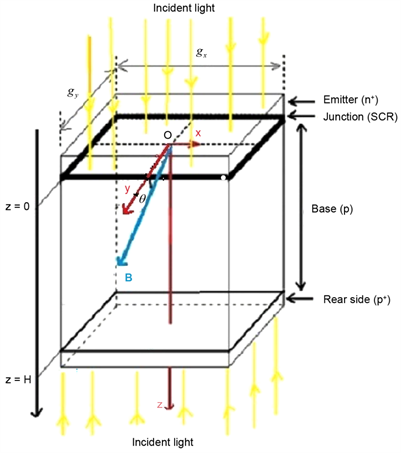
Figure 1. Grain of bifacial polycrystalline silicon solar cell illuminated by multispectral light and under the influence of incidence angle of magnetic field.
・ the grain boundaries are perpendicular to the junction and their recombination velocity Sgb is constant along the grain boundaries and independent of illumination up to AM 1 [20] so under AM 1.5 which is the standard spectrum for measuring the efficiency of solar cells used on the surface of the earth [21] ;
・ the grain and by extrapolation the polycrystalline silicon solar cell have a high n-type doped emitter so that the contribution on the performance of the cell comes from the p-type base region [18] ;
・ the p-type base is quasi-neutral (quasi-neutral base assumption) so that only the junction electric field will be taken into account [22] ;
・ the effect of temperature is not taken into account on the performance of the solar cell;
・ the magnetic field is constant and it is applied into the base region in the plan (O, y, z) with an incidence angle θ with the axis Oy: .
When the grain of the bifacial polycrystalline silicon solar cell represented in Figure 1 is illuminated simultaneously on both sides with a multispectral light, the continuity equation for the density of excess minority carriers photogenerated in the base is given by Equation (1) [20] :
(1)
with , and are
the electron diffusion coefficient and diffusion length depending on the applied magnetic field.
d(x, y, z) and G(x) are respectively the density of carriers and the optical generation rate of carriers for a multispectral incident light. B0 and θ are respectively the intensity and the incidence angle of the applied magnetic field while μn is the electrons mobility.
The density of the excess minority carriers photogenerated in the base of the polycrystalline silicon grain, general solution of the continuity equation, is expressed by Equation (2) [20] :
(2)
with , , and
is the electron diffusion coefficient depending on the magnetic field and its incidence angle. Coefficients ai and bi are tabulated values obtained from modelling of the generation rate considered for over all the solar radiation spectrum under Air Mass 1.5 standard conditions [11] [23] . Coefficients and are solved for using the boundary conditions of the solar cell [14] [20] while coefficients and are found using the grain boundary conditions [14] [20] .
The expression of the photocurrent density at the junction of the polycrystalline silicon grain is given by Equation (3) [20] :
(3)
The expression of the photovoltage across the junction of the polycrystalline silicon grain is expressed using Boltzmann’s relation [14] :
(4)
VT is the thermal voltage, NB the base doping density and ni the intrinsic concentration of electrons at thermodynamic equilibrium.
The expression of the electric power provided by the polycrystalline silicon grain to an external circuit is expressed by Equation (5):
(5)
The conversion efficiency of the polycrystalline silicon grain is calculated, for various incidence angle of the magnetic field, using Equation (6):
(6)
The power of the incident light under AM 1.5 standard conditions, used, is Pinc = 100 mW/cm2.
Knowing the short-circuit photocurrent density, the open-circuit photovoltage and using Equation (7), the fill factor of the polycrystalline silicon grain is calculated according to the incidence angle of the magnetic field:
(7)
3. Results and Discussion
3.1. Effect of the Incidence Angle of the Magnetic Field on the Diffusion Coefficient
The curve of diffusion coefficient versus incidence angle of the magnetic field is plotted in Figure 2.
The curve in Figure 2 shows that the diffusion coefficient increases for incidence angle varying from θ = 0 rad to θ = π/2 rad and from θ = π rad to θ = 3π/2 rad while it decreases for incidence angle varying from θ = π/2 rad to θ = π rad and from θ = 3π/2 rad to θ = 2π rad. In fact, for incidence angle varying from θ = 0 rad to θ = π/2 rad and from θ = π rad to θ = 3π/2 rad the strength of Lorentz, that deviates the electrons photogenerated in the base of the solar cell, decreases until its cancellation resulting in an increase of the quantity of carriers that diffuse through a unit surface per second. For incidence angle varying from θ = π/2 rad to θ = π rad and from θ= 3π/2 rad to θ = 2π rad, the reverse behaviour is observed. Thus, the diffusion coefficient versus incidence angle of the magnetic field is a positive periodic sinusoidal function which period is π. Consequently, all electronic and electrical parameters proportional to the diffusion coefficient will have the same behaviour as the diffusion coefficient.
3.2. Effect of the Incidence Angle of the Magnetic Field on the Short-Circuit Photocurrent Density
Figure 3 plots the curve of short-circuit photocurrent density versus incidence angle of the magnetic field.

Figure 2. Diffusion coefficient versus incidence angle of magnetic field (Dn = 26 cm2/s; μn = 103 cm2/V.s, B0 = 7.5 mT).
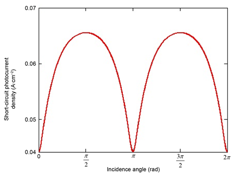
Figure 3. Short-circuit photocurrent density versus incidence angle of magnetic field (Dn = 26 cm2/s; μn = 103 cm2/V.s, B0 = 7.5 mT, Ln = 0.015 cm; H = 0.03 cm, gx = gy = 3 × 10⁻³ cm; Sb = 103 cm/s; Sgb = 102 cm/s, Sf = 8 × 108 cm/s).
The curve in Figure 3 has the same behaviour than the one of the diffusion coefficient in Figure 2 because the photocurrent density and therefore the short-circuit photocurrent density are proportional to the diffusion coefficient. So, the strength of Lorentz which influences the carriers’ diffusion towards the junction will also influence the short circuit photocurrent. Indeed, for the incidence angles of the applied magnetic field: θ = 0 rad, θ = π rad and θ = 2π rad, the direction of the magnetic field vector is orthogonal to the direction of the velocity vector of the electrons resulting in a maximum effect of the strength of Lorentz. In this situation, the strength of Lorentz deviates the electrons photogenerated resulting in a reduction of the quantity of carriers which can cross the junction and then the short-circuit photocurrent density is minimum. On the other hand, for the incidence angles of the applied magnetic field: θ = π/2 rad and θ = 3π/2 rad, the direction of the magnetic field vector is collinear to the direction of the velocity vector of the electrons. For this orientation, the strength of Lorentz is null and so it does not has any effect on the movement of the electrons towards the junction. The maximum of carriers can reach to the junction and cross it and then the short-circuit photocurrent density is maximum.
3.3. Effect of Incidence Angle of the Magnetic Field on the Open-Circuit Photovoltage
The curve of open-circuit photovoltage is plotted versus incidence angle of the magnetic field in Figure 4.
The curve in Figure 4 shows that the open-circuit photovoltage decreases for values of the incidence angle θ of the magnetic field included between the intervals [0, π/2] and [π, 3π/2], while it increases for incidence angle θ included between
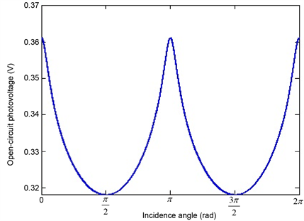
Figure 4. Open-circuit photovoltage versus incidence angle of magnetic field (Dn = 26 cm2/s; μn = 103 cm2/V.s, B0 = 7.5 mT, Ln = 0.015 cm; H = 0.03 cm, gx = gy = 3 × 10⁻³ cm; Sb = 103 cm/s; Sgb = 102 cm/s, Sf = 0 cm/s).
the intervals [π/2, π] and [3π/2, 2π]. The maximum values of the open-circuit photovoltage are observed at the values of the incidence angle θ equal to 0 rad, π rad and 2π rad and the minimum one’s at the incidence angle θ equal to π/2 rad and 3π/2 rad. It was proved in previous studies [11] [15] that, the increase of the magnetic field leads to an increase of carriers’ storage near the junction. Thus, the increase of the incidence angle θ of the magnetic field from θ = 0 rad to θ = π/2 rad and from θ = π rad to θ = 3π/2 rad which means a reduction of the magnetic field effect on the carriers photogenerated in the base leads then to the decrease of the carriers concentration in the base. The open-circuit photovoltage being a function of carriers concentration near the junction, the increase of the incidence angle θ of the magnetic field leads to the decrease of the open circuit photovoltage in the intervals [0, π/2] and [π, 3π/2] while it increases in the intervals [π/2, π] and [3π/2, 2π]. The maximum values of the open-circuit photovoltage are observed at the maximum influence of magnetic field which corresponds to the incidence angle θ equal to 0 rad, π rad and 2π rad and the minimum one’s at the incidence angle θ equal to π/2 rad and 3π/2 rad.
The curve in Figure 4 has the reverse behaviour of the curve of diffusion coefficient in Figure 2 and short-circuit photocurrent density in Figure 3. Despite this reverse behaviour, the open-circuit photovoltage versus incidence angle of the magnetic field is a positive periodic sinusoidal function which period is π.
3.4. Effect of the Incidence Angle of the Magnetic Field on the Electric Power-Photovoltage Characteristics
The curves of electric power versus photovoltage for various incidence angle of the magnetic field are plotted in Figure 5.
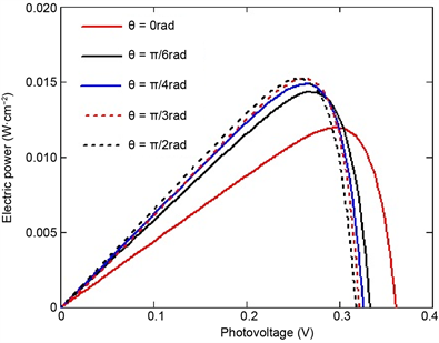
Figure 5. Electric power-photovoltage curves for various incidence angle of magnetic field (Dn = 26 cm2/s; μn = 103 cm2/V.s, B0 = 7.5 mT, Ln = 0.015 cm; H = 0.03cm, gx = gy = 3 × 10⁻³ cm; Sb = 103 cm/s; Sgb = 102 cm/s).
Curves in Figure 5 have the same shape than those of previous works [12] [16] . We observe on the curves in Figure 5 that for the values of the incidence angle of the applied magnetic field varying from θ = 0 rad to θ = π/2 rad, the maximum electric power increases with the increase of incidence angle while the open-circuit photovoltage decreases. This behaviour is the consequence of the decrease of the strength of Lorentz until its cancellation.
3.5. Electrical Parameters of the Polycrystalline Silicon Grain
As the diffusion coefficient, the short-circuit photocurrent density and the open-circuit photovoltage are symmetrical compared with θ = π/2 rad, consequently the modelling of the effect of the incidence angle of the magnetic field on the electrical parameters of the polycrystalline silicon grain will be conducted in the range of θ = 0 rad to θ = π/2 rad.
By means of the curves of Figures 3-5 we find successively, for various incidence angle of the magnetic field, the short-circuit photocurrent density, the open-circuit photovoltage and the maximum electric power. The conversion efficiency and the fill factor of the polycrystalline silicon grain are calculated using respectively Equations (6) and (7). The electrical parameters of the polycrystalline silicon grain for various incidence angle of the magnetic field are given in Table 1.
These results show that the maximum electric power and consequently the conversion efficiency increase with the increase of the incidence angle of the magnetic field while the fill factor decreases. The increase of the maximum electric power and the conversion efficiency of the polycrystalline silicon grain with the increase of the incidence angle of the magnetic field shows a way to decrease the negative effect of a magnetic field on solar cells. One must tilt solar cells in order that the lines of magnetic field make an incidence angle non-null with the junction of these solar cells.
4. Conclusion
Three-dimensional modelling of the effect of incidence angle of a magnetic field on the performance of a grain of polycrystalline silicon solar cell has been investigated. This study showed that the maximum electric power and the conversion

Table 1. Electrical parameters of the polycrystalline silicon grain according to the incidence angle of magnetic field.
efficiency of the polycrystalline silicon grain increase with the increase of the incidence angle of the magnetic field. It appears also through this study that the degradation of the solar cells performance induced by the application of a magnetic field can be reduced by increasing the incidence angle of the magnetic field. These results show also that the negative effect of a magnetic field on solar cells can be limited by tilting the cells so that the lines of magnetic field make an incidence angle non-null with the junction of the cells.
Acknowledgements
The authors are grateful to International Science Program (ISP) for supporting their research group (energy and environment) and allowing them to conduct this work.
Cite this paper
Sourabié, I., Zerbo, I., Zoungrana, M., Combari, D.U. and Bathiebo, D.J. (2017) Effect of Incidence Angle of Magnetic Field on the Performance of a Polycrystalline Silicon Solar Cell under Multispectral Illumination. Smart Grid and Renewable Energy, 8, 325-335. https://doi.org/10.4236/sgre.2017.810021
References
- 1. Nema, S., Nema, R.K. and Agnihotri, G. (2010) Matlab/Simulink Based Study of Photo-voltaiccells/Module/Array and Their Experimental Verification. International Journal of Energy and Environment, 1, 487-500.
- 2. Asghar, S.B. and Singh, R.K. (2015) Simulink Based Analysis and Realization of Solar PV System. Energy and Power Engineering, 7, 546-555. https://doi.org/10.4236/epe.2015.711051
- 3. Skoplaki, E. and Palyvos, J.A. (2009) On the Temperature Dependence of Photovoltaic Module Electrical Performance: A Review of Efficiency/Power Correlations. Solar En-ergy, 83, 614-624. https://doi.org/10.1016/j.solener.2008.10.008
- 4. Alsayid, B.A., Alsadi, S.Y., Jallad, J.S. and Dradi, M.H. (2013) Partial Shading of PV System Simulation with Experimental Results. Smart Grid and Renewable Energy, 4, 429-435. https://doi.org/10.4236/sgre.2013.46049
- 5. Boukebbous, S.E. and Kerdoun, D. (2015) Study, Modeling and Simulation of Photo-voltaic Panels under Uniform and Non-Uniform Illumination Conditions. Revue des Energies Renouvelables, 18, 257-268.
- 6. Kazem, H.A., Khatib, T., Sopian, K., Buttinger, F., Elmenreich, W. and Albusaidi, A.S. (2013) Effect of Dust Deposition on the Performance of Multi-Crystalline Photovoltaic Modules Based on Experimental Measurements. International Journal of Renewable Energy Research, 3, 850-853.
- 7. Betser, Y., Ritter, D., Bahir, G., Cohen, S. and Sperling, J. (1995) Measurement of the Minority Carrier Mobility in the Base of Heterojunction Bipolar Transistor Using Magneto-Transport Method. Applied Physics Letter, 67, 1883-1884. https://doi.org/10.1063/1.114364
- 8. Vardanyan, R.R., Kerst, U., Wawer, P. and Wagemann, H. (1998) Method for Measure-ment of All Recombination Parameters in the Base Region of Solar Cells. Proceedings of the 2nd World Conference and Exhibition on Photovoltaic Solar Energy Conversion, Vienna-Austria, 6-10 July 1998, Vol. I, 191-193.
- 9. Madougou, S., Made, F., Boukary, M.S. and Sissoko, G. (2007) I–V Characteristics for Bifacial Silicon Solar Cell Studied under a Magnetic Field. Advanced Materials Research, 18-19, 303-312. https://doi.org/10.4028/http://www.scientific.net/AMR.18-19.303
- 10. Zouma, B., Maiga, A.S., Dieng, M., Zougmoré, F. and Sissoko, G. (2009) 3D Approach of Spectral Response for a Bifacial Silicon Solar Cell under a Constant Magnetic Field. Global Journal of Pure and Applied Sciences, 15, 117-124. https://doi.org/10.4314/gjpas.v15i1.44908
- 11. Zerbo, I., Zoungrana, M., Sourabie, I., Ouedraogo, A., Zouma, B. and Bathiebo, D.J. (2015) External Magnetic Field Effect on Bifacial Silicon Solar Cell’s Electric Power and Conversion Efficiency. Turkish Journal of Physics, 39, 288-294. https://doi.org/10.3906/fiz-1505-10
- 12. Zerbo, I., Zoungrana, M., Sourabie, I., Ouedraogo, A., Zouma, B. and Bathiebo, D.J. (2016) External Magnetic Field Effect on Bifacial Silicon Solar Cell’s Electrical Parameters. Energy and Power Engineering, 8, 146-151. https://doi.org/10.4236/epe.2016.83013
- 13. Sané, M. and Barro, F.I. (2015) Effect of Both Magnetic Field and Doping Density on Series and Shunt Resistances under Frequency Modulation. Indian Journal of Pure and Applied Physics, 53, 590-595.
- 14. Zoungrana, M., Zerbo, I., Ouedraogo, F., Zouma, B. and Zougmoré, F. (2012) 3D Modelling of Magnetic Field and Ligth Concentration Effects on a Bifacial Silicon Solar Cell Illuminated by its Rear Side. IOP Conference Series: Materials Science and Engineering, 29, Article ID: 012020. http://iopscience.iop.org/1757-899X/29/1/012020 https://doi.org/10.1088/1757-899X/29/1/012020
- 15. Zoungrana, M., Zerbo, I., Soro, B., Savadogo, M., Tiedrebeogo, S. and Bathiebo, D.J. (2017) The Effect of Magnetic Field Effect on the Efficiency of a Silicon Solar Cell under an Intense Light Concentration. Advances in Science and Technology Research Journal, 11, 133-138. https://doi.org/10.12913/22998624/69699
- 16. Combari, D.U., Zerbo, I., Zoungrana, M., Ramde, E.W. and Bathiebo, D.J. (2017) Modelling Study of Magnetic Field Effect on the Performance of a Silicon Photovoltaic Module. Energy and Power Engineering, 9, 419-429. https://doi.org/10.4236/epe.2017.98028
- 17. Ba, B. and Kane, M. (1995) Open-Circuit Voltage Decay in Polycrystalline Silicon Solar Cells. Solar Energy Materials and Solar Cells, 37, 259-271.
- 18. Ba, B., Kane, M. and Sarr, J. (2003) Modelling Recombination Current in Polysilicon Solar Cell Grain Boundaries. Solar Energy Materials and Solar Cells, 80, 143-154.
- 19. Ouedraogo, A., Barandja V.D.B., Zerbo, I., Zoungrana, M., Ramde, E.W. and Bathiebo, D.J. (2017) A Theoretical Study of Radio Wave Attenuation through a Polycrystalline Silicon Solar Cell. Turkish Journal of Physics, 41, 314-325. https://doi.org/10.3906/fiz-1703-16
- 20. Dugas, J. (1994) 3D Modelling of a Reverse Cell Made with Improved Multicrystalline Silicon Wafers. Solar Energy Materials and Solar Cells, 32, 71-88.
- 21. Würfel, P. (2005) Physics of Solar Cells: From Principles to New Concepts. WILEY-VCH Verlag GmbH & Co. KGaA, Weinheim.
- 22. Misiakos, K., Wang, C.H., Neugroschel, A. and Lindholm, F.A. (1990) Simultaneous Ex-traction of Minority Carrier Parameters in Crystalline Semiconductors by Lateral Photocurrent. Journal of Applied Physics, 67, 321-331. https://doi.org/10.1063/1.345256
- 23. Mohammad, S.N. (1987) An Alternative Method for the Performance Analysis of Silicon Solar Cells. Journal of Applied Physics, 61, 767-772. https://doi.org/10.1063/1.338230