Energy and Power Engineering
Vol.10 No.08(2018), Article ID:86716,15 pages
10.4236/epe.2018.108022
Data Logging and Control of a Remote Inverter Using LoRa and Power Line Communication
K. A. Terashmila Lasagani, Tariq Iqbal, George K. Mann
Department of Electrical and Computer Engineering, Memorial University of Newfoundland, St. John’s, Canada

Copyright © 2018 by authors and Scientific Research Publishing Inc.
This work is licensed under the Creative Commons Attribution International License (CC BY 4.0).
http://creativecommons.org/licenses/by/4.0/


Received: May 9, 2018; Accepted: August 14, 2018; Published: August 17, 2018
ABSTRACT
For decades, the power system was highly centralized. With the growing integration of distributed generations into the system, there is a necessity for bi-directional communication methods to monitor and control the remote assets. The primary objective of this paper is to develop a communication link for monitoring and controlling a grid-connected inverter in a remote location. Furthermore, the paper presents developments that have been incorporated to improve the communication link. The literature survey indicates that LoRa is superior compared to other technologies, but has some security and reliability issues. This paper also presents an encryption algorithm to improve the security of the LoRa link. Local data storage added to the system before transmitting data increases the system reliability. A display at the transmission end is added to improve the user-friendliness of the communication link. A Powerline Communication link is parallelly added to the LoRa link to improve the reliability. Finally, tests are conducted with an actual inverter and the results are presented. The tests show that the developed communication link has improved security and reliability, while its open nature makes it highly scalable and adaptable for employment in other smart grid applications.
Keywords:
LoRa Application, Supervisory Control and Data Acquisition System, Inverter Remote Control, Power Line Communication

1. Introduction
The recent development of renewable power generation and energy storage systems has increased the distributed nature of the power system. Only a few decades ago, the power system was centrally controlled with no small power generations. The power system requires integrated automated management with reliable real-time information that smoothly matches demand and supply. Even small distributed generators (DG) require control for unhindered operation. Therefore, given the increasingly distributed nature of the power system, a central Supervisory Control and Data Acquisition (SCADA) system is essential for the remote monitoring and controlling of a grid-connected inverter. Figure 1 provides a schematic for the master SCADA station and the remote SCADA stations connected to the distributed resources.
In typical configurations of SCADA systems, both wired and wireless communication technologies have been employed to serve the monitoring and control objectives. Wired technologies such as Powerline Communication (PLC), Optical-fiber communication, and Digital Subscriber Lines (DSL) are employed, as well as wireless technologies such as Cellular Network Communication, Bluetooth, and Wi-Fi. While each of these techniques has its inherent pros and cons, opportunities exist for improved approaches for communication between the master and remote SCADA stations.
Therefore, this paper addresses the gap that exists for a secure, reliable, and low-cost communication method by demonstrating a novel communication method for remote monitoring and control with extended range, and increased levels of protection, and high reliability based on state-of-the-art technology through the use of LoRa in combination with PLC.
The paper is organized as follows. Section 2 explains the methodology followed and the development of the SCADA, while Section 3 proposes a solution to improve reliability and overcome temporary data losses through a LoRa and PLC based redundancy system within the proposed communication model. Section 4 critically reviews the developed communication channel on several fronts including security, reliability, scalability, quality of service, etc. Section 5 provides conclusions for the paper and discusses the direction for future work.

Figure 1. A typical arrangement of a SCADA system.
According to the literature survey, both wired and wireless communication methods are utilized in SCADA communications.
1.1. Wired Technologies
There are a handful of wired technologies that are in use in SCADA applications. While a literature survey reveals there are many publications discussing DSL and other state-of-the-art technologies such as fiber optics, Powerline Communication (PLC) can be considered as the best wired technology due to the existing infrastructure for smart grid applications.
Powerline Communication (PLC) is a wired communication technology that uses power lines for communication purposes. M. Y. Zhai et al. [2] present the measurement results of channel properties of low-voltage (LV) PLC systems after giving a general overview of the topologies for the typical LV distribution networks in China. However, the work does not address the presence of transformer issues in PLC.
S. Bavarian et al. [3] give a comprehensive overview for PLC. In general, using power lines, smart meters and data concentrators have been connected to the PLC network, and using cellular technologies, data is being transferred to the data center. Using this approach, by connecting any electrical device to the power line, such as a power line smart transceiver-based meter, data can be transmitted to a central location.
Z. Wang et al. [4] proposed a novel method using PLC, by combining PLC and wireless technology to solve the uplink channel problem in non-signal or poor-signal areas encountered in the on-site implementation. At present, wireless communication modules of the concentrator are installed as discrete modules. The uplink wireless communication and the local power line communication were achieved by the internal gateway of the concentrator.
1.2. Wireless Technologies
Typically, wireless technologies such as Bluetooth, Wi-Fi, Radio Teletype, UHF/VHF Wireless Data Transmission, Satellite Communication, and Zigbee are used in SCADA communication. E.C.-H. Ngai et al. [1] discuss low power data communication options for the Internet of Things (IoT). Table 1 summarizes features of wireless technologies based on the complete literature survey. LoRa, Radio Teletype, and UHF/VHF data transmission can be identified as low-cost and long-range options as per this comparison of features. Based on the results published by T.K.A. Lasagani et al. [5] , LoRa can be recognized as the best available technology from the three highlighted options.
LoRa communication technology is one of the promising wide-area IoT technologies which was introduced by Semtech and the Long Range Wide Area Network (LoRaWAN) protocol specification for the technology was developed and is further promoted by the LoRa Alliance [9] .
J. So et al. [10] have discussed the execution of the LoRa network server on

Table 1. Comparison of available wireless technologies.
OpenStack. By taking advantage of the system services provided by OpenStack, they have been able to update the operations of the LoRa network server to achieve flexible and scalable service. They developed an experimental set up using commercially available hardware related to LoRa and available open sources for LoRa terminal, LoRa gateway and OpenStack software to validate their LoRa network server on the OpenStack platform. J. Kim et al. [11] present a dual-key scheme for increasing LoRa security. The suggested scheme is good but its computing requirements would necessitate significantly more power and increase system costs. To satisfy the demand for low-power, long-range, high-data transmission which arises with the commercialization of IoT, D. Kim et al. [12] have introduced a method which combines LoRa and Wi-Fi services. Though LoRa can provide low-power, long-range communication, its data transmission rate is small. Therefore, to address the requirement to send large amounts of data, the authors have chosen Wi-Fi service to satisfy the high-data rate problem. Using these two technologies, they have introduced a multi-interface communication module which can achieve long-range and low-power requirements using LoRa and a large amount of data using wireless LAN (wi-fi).
To study the coverage of LoRaWAN technology, J. Petajajarvi et al. [13] have experimented using commercially available equipment, particularly for two cases in the city of Oulu, Finland. They collected measurements by connecting a node on the ground and a node on the water, both reporting data to a base station. Using this information, they have estimated the communication range of LoRaWAN as 15 km on ground and 30km on water. Furthermore, a channel attenuation model derived using the collected data from the experiment is also presented.
2. Methodology
The body of research literature on the application of LoRa is small, and the survey did not identify any developments or publications regarding the usage of LoRa for SCADA systems or monitoring and controlling of an inverter. For such evolving IoT power system communication, security and safety are vital concerns. As per the literature, an AES encryption algorithm improves the security of a LoRaWAN network. Researchers have not addressed the safety of a LoRa link used outside a LoRaWAN for private communication. AES encryption slows the process when used in an Arduino. Therefore, this paper develops a device that can be utilized for monitoring and controlling of an inverter using LoRa. The method also facilitates use of a local storage system to improve reliability.
The following section explains the methodology used to improve the LoRa communication link. Since the primary objective of the research is to develop a communication link for monitoring and controlling of an inverter, the two sides of the communication link are designated as the inverter side and the server side. Figure 2 illustrates the two sides of the system as described.
2.1. Inverter Side
The inverter side is principally responsible for the following essential tasks, around which the Arduino MEGA based system has been designed and tested:
1) Communicating with the inverter through RS232 port,
2) Storing and displaying data using a SD card and a local LCD display, and
3) Securely and efficiently communicating with the server side.
2.1.1. Physical Arrangement
Figure 3 shows the physical arrangement of the circuit where Arduino MEGA is acting as the master. To save and display received data, the Master MEGA board sends data to another Arduino MEGA connected to the circuit using UART protocol. The above said slave board then transmit data to the TFT display for displaying purposes and data logging purposes using SPI protocol. Figure 4 illustrates the stacked circuits, and this method allows the user to save space.
1) Arduino Mega [14] : Arduino Mega is a microcontroller based on ATmega2060 which lost of sophisticated features.
2) LoRa transceiver [15]
3) RS232 converter: A RS232 interface communicate with the inverter using UART protocol.
4) Thin-film-transistor liquid-crystal display [16] : This is an Arduino compatible liquid crystal display.

Figure 2. Server and Inverter side electronics.

Figure 3. Inverter Side block diagram.

Figure 4. Actual circuit layout.
2.1.2. Main algorithm for the Inverter Side
A. Silva et al. [17] discuss power management in a communication network. Power management could be achieved by putting the Arduino and LoRa module in sleep mode when it is not transmitting or receiving. However, this can add an additional burden to the Arduino. In their paper Z. Jiang et al. [18] talk about an innovative scheduling scheme for IoT communication. Although the proposed scheme shows advantages, the necessity for additional computing resources and thereby increased power consumption was not a desirable research outcome. Therefore, the main algorithm is developed to perform the three main tasks stated above. As per Algorithm 1, the master MEGA acquires data from the inverter and sends it to the slave MEGA for displaying and data logging purposes. The data communications are encrypted for security purposes. The received inverter data is then transmitted to the server using LoRa after this encryption. As the next step, the master MEGA will wait a maximum of 5 seconds to receive data from the server side. If it receives data, the decrypted data will be sent to the inverter.
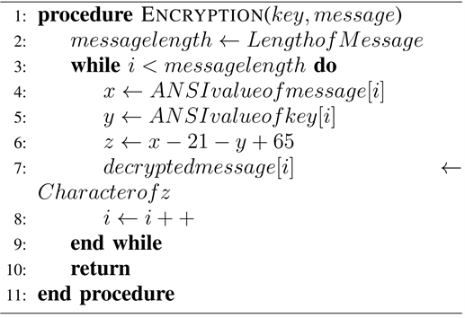
2.1.3. Encryption and Decryption Algorithms
The primary objective of these algorithms is to improve the security of the communication link by encrypting data using two encryption methods. The first method uses a shift cipher. The second method uses Vigenere Cipher with a key word and shifting each letter in the plain text by a different number per each letter in the key word. Since in most SCADA applications, plain text has a constant length, the key word is selected such that it would be longer than the plain text. Therefore, each letter is shifted differently. The algorithm for the encryption is shown in Algorithm 2. For decryption, the encrypted message is deciphered as per the algorithm shown in Algorithm 3.
2.1.4. Data Processing Algorithm
Data coming from the inverter are sent to the slave MEGA for displaying and data logging purposes. At the beginning of the program, it reads data stored in the EEPROM for time setting goals and self-sets the date and time. Also, it allows the user to set date and time, whereby if the user does not adjust the time within 5 seconds, the system will automatically take the saved date/time on the EEPROM as the present date and time. Then the algorithm sets up the SD card. After the setup, the main loop runs which starts with taking serial input from the
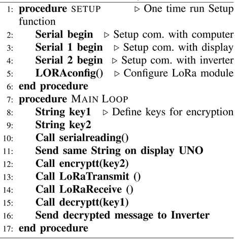
Algorithm 1. LoRa MEGA algorithm.

Algorithm 2. Encryption algorithm.
Algorithm 3. Decryption algorithm.
Master MEGA. The data string for the developed application is coming as a HEX string. And it also comes in Little Endian format. As the next step of the algorithm, the data string will be split and converted into DEC for displaying and data logging. This algorithm is explained in the pseudo code given in Algorithm 4.
2.1.5. Save data on the SD Card Algorithm
The next important feature that the system offers is the data logging on the SD card. The data string is split into parts and saved in the card for each 5 second interval in CSV format. The information contains a time stamp, voltage, current, power, the version number of the inverter respectively. The advantage of this CSV file is that it can be directly uploaded to an IoT server which has been developed as another component of this research.
Transferred data is supposed to be saved at a secure location. Therefore, there is no requirement to keep data inside the local SD storage for a long period of time. Hence, data will only be stored for seven days. Algorithm 5 addresses this issue. Since data is saved for each 5 seconds, 17,280 data strings are saved for a

Algorithm 4. Data processing algorithm.
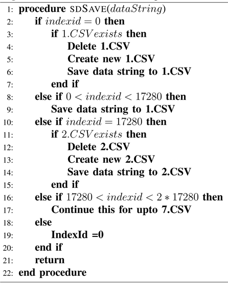
Algorithm 5. Save Data on SD algorithm.
day (12 × 60 × 24). After keeping data for seven days, the algorithm automatically deletes it.
2.2. Server Side
On the server side, the LoRa SX1272 module is connected to an Arduino UNO and that component will communicate with the server computer through a USB port. Algorithm 6 outlines the algorithm used on the server-side Arduino UNO.
2.3. Testing with an Actual Inverter
This paper is part of a larger research project being funded by the NSERC Energy Storage Network fund. The objective of this portion of the research being conducted at Memorial University of Newfoundland (MUN) is to develop low cost SCADA system for power converters. Upon completion, the developed LoRa system has been tested with the inverter developed in the University of New Brunswick (UNB) Sustainable Power Research Lab. Figure 5 show the inverter developed by UNB. They are using a DSP2407A board for communication purposes with the inverter, and as shown in Figure 6 that board has a RS232 port for UART communication. The inverter side of the developed communication channel has been connected to the serial port. Data strings are sent by the inverter according to the protocol shown below. The data strings have been successfully decoded by the system and communicated to the other side through the LoRa link. Figure 7 shows data available on the display on the developed system as well as the inverter itself.
Decoding: Sample data string,
55AA0200000064BF07001B4A76001B3E1E00A6009C02400FF71C643B1231
In the data string, the first two bytes represent the synchronous word and the next four bytes represent the status, where the next twelve bytes represent data as current, voltage and power respectively in four bytes. Then number of samples, maximum voltage and the maximum current value and the version number sent in two bytes each respectively. The following equations are implemented in the Arduino Mega. Equation (1) shows the decoding of current and Equation (2)

Algorithm 6. LoRa UNO algorithm.
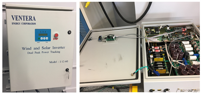
Figure 5. Wind and Solar Inverter Developed by UNB.
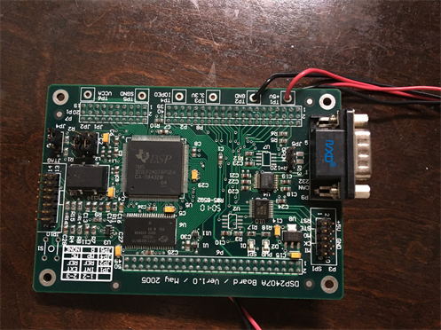
Figure 6. DSP board used for communication.
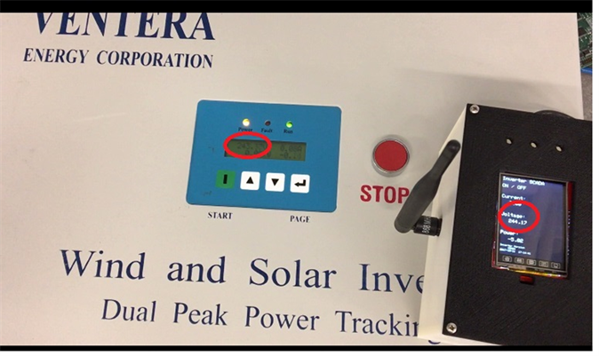
Figure 7. Displaying decoded data on the system and the inverter.
shows the decoding of the voltage and Equation (3) shows the decoding of the real power.
(1)
(2)
(3)
2.4. Results
The proposed system has been prototyped and tested in the field environment. It successfully communicated up to 4.5 km range at the medium power level, and after decoding, values are displayed on the display and stored in the SD card.
3. LoRa and Power Line Carrier Communication Based Redundant Model
Wireless networks are inherently vulnerable since interferences by a third party are simple. LoRa uses the free ISM band and anyone can use the same band, leaving data transmissions open to higher interferences and signal noise. Methods such as slow frequency hopping will be helpful to overcome this issue. However, in cases where the entire band is interfered, then frequency hopping will not be helpful. To overcome temporary data losses a SD card based local storage is added to the system. But this does not solve the communication loss between the server and the inverter which is more critical than the data loss.
Therefore, to improve the reliability of a LoRa communication link this section proposes a solution by combining a PLC based solution with an added LoRa solution, in cases where use of PLC is possible. To achieve the objective of improved reliability, the inverter side of the developed LoRa link is connected to a Raspberry PI using the USB port of the Arduino Mega through the serial interface. The same data string received by the Arduino Mega through the Serial2 interface is written on the Serial0 interface. Raspberry PI is connected to a one end of the PLC module. As Figure 8 emphasizes, data flows in two communication channels, where one set of data flows through the power lines and the same data set flows through the LoRa as wireless. This redundant system will improve the reliability of the communication model.
4. Discussion
This section critically reviews the developed channel regarding security, reliability, scalability and the quality of service.
4.1. Security
Security of the developed channel has been achieved through an embedded encryption which ensures the confidentiality of data by preventing disclosure of

Figure 8. Block Diagram for LoRa and PLC Setup.
information to unauthorized persons. The cyclic redundancy check algorithm embedded into the LoRa algorithm guarantees the integrity of data. There are some issues regarding availability where a hacker can jam the signal, an issue the developed channel shares with all wireless technique. Since there is a local storage of data, short-term data jamming can be ignored.
Overall, the developed system has an improved security compared to a LoRa link without encryption.
4.2. System Reliability, Robustness and Availability
Reliability of the system is critical in smart grid applications. LoRa itself has inherent robustness. The addition of local storage has improved the data redundancy. The proposed two channel model is more reliable than the time division multiplexing model.
4.3. Scalability
For the aspect of scalability, the developed system has many advantages compared to available technologies due to the open source nature. Developers can comfortably adopt this system to their specific smart grid applications while ensuring strong security and reliability attributes for the system.
5. Conclusion and Future Works
Monitoring and controlling of energy storage has become highly important for dispatching purposes. This paper mainly discusses selection and development of an open source communication channel for monitoring and controlling of a remote inverter. In the first part of the article, three open source communication methods are tested in terms of power consumption, the range of communication, and the data rate. At the end of the first portion of the paper, a LoRa based communication link is selected as the best communication method.
The second part proposes and implements methodology to develop the LoRa link, adding algorithms to improve its performance. Changes are also included for adding security features, reducing power consumption and improving data redundancy. To enhance security, an encryption algorithm has been added. Data redundancy has been increased through the use of local storage for the inverter side. As well, local data display is provided to the system to improve user friendliness.
From field testing, it has been verified that this communication link can be used for secure communication between a SCADA and a controlled device. Though the system developed is specifically for an inverter, it can be easily converted for use in secure communication for power system dispatching. As future works, power consumption improvements will be made to reduce the phantom load of the system.
Acknowledgements
The authors would like to thank NSERC Energy Storage Network (NESTNET) for funding and WEICan for their support.
Conflict of Interest
The authors declare that there are no conflicts of interest regarding the publication of this paper.
Cite this paper
Lasagani, K.A.T., Iqbal, T. and Mann, G.K. (2018) Data Logging and Control of a Remote Inverter Using LoRa and Power Line Communication. Energy and Power Engineering, 10, 351-365. https://doi.org/10.4236/epe.2018.108022
References
- 1. Sathyamoorthy, P., Ngai, E.C.-H., Hu, X. and Leung, V.C.M. (2017) Profiling Energy Efficiency and Data Communications for Mobile Internet of Things. Wireless Communications and Mobile Computing, 2017, Article ID: 6562915.
- 2. Zhai, M.Y. (2011) Transmission Characteristics of Low-Voltage Distribution Networks in China under the Smart Grids Environment. IEEE Transactions on Power Delivery, 26, 173-180. https://doi.org/10.1109/TPWRD.2010.2067228
- 3. Bavarian, S. and Lampe, L. (2012) Communications and Access Technologies for Smart Grid. In: Hossain, E., Han, Z. and Poor, H.V., Eds., Smart Grid Communications and Networking, Cambridge University Press, Cambridge, 111-146. https://doi.org/10.1017/CBO9781139013468.006
- 4. Wang, Z., Ge, W., Wang, C. and Zeng, C. (2012) The Applications of Networking of Consumption Data Acquisition System by Combining Broadband Powerline Communication and Wireless Communication. IEEE PES Innovative Smart Grid Technologies, Tianjin, 21-24 May 2012, 1-4.
- 5. Lasagani, T.K.A., Iqbal, T. and Mann, G. (2017) A Comparison of Low Cost Wireless Communication Methods for Remote Control of Grid-Tied Converters. IEEE 30th Canadian Conference on Electrical and Computer Engineering (CCECE), Windsor, ON, 31 October 2017, 1-4.
- 6. Zhou, H.J., Guo, C.X. and Qin, J. (2010) Efficient Application of GPRS and CDMA Networks in SCADA System. IEEE PES General Meeting, Providence, RI, 25-29 July 2010, 1-6.
- 7. Fu, C. and Ni, Z. (2015) The Application of Embedded System in Supervisory Control and Data Acquisition System (SCADA) over Wireless Sensor and GPRS Networks. IEEE 9th International Conference on Anti-counterfeiting, Security, and Identification (ASID), Xiamen, 25-27 September 2015, 81-85. https://doi.org/10.1109/ICASID.2015.7405666
- 8. Conti, M., Fedeli, D. and Virgulti, M. (2011) B4V2G: Bluetooth for Electric Vehicle to Smart Grid Connection. Proceedings of the Ninth International Workshop on Intelligent Solutions in Embedded Systems, Regensburg, 7-8 July 2011, 13-18.
- 9. Hossain, E., Han, Z. and Poor, H. V. (2012) Smart Grid Communications and Networking. Cambridge University Press, Cambridge. https://doi.org/10.1017/CBO9781139013468
- 10. So, J., Kim, D., Kim, H., Lee, H. and Park, S. (2016) LoRaCloud: LoRa Platform on OpenStack. IEEE NetSoft Conference and Workshops (NetSoft), Seoul, 6-10 June 2016, 431-434. https://doi.org/10.1109/NETSOFT.2016.7502471
- 11. Kim, J. and Song, J. (2017) A Dual Key-Based Activation Scheme for Secure LoRaWAN. Wireless Communications and Mobile Computing, 2017, Article ID: 6590713.
- 12. Kim, D.H., Lim, J.Y. and Kim, J.D. (2016) Low-Power, Long-Range, High-Data Transmission Using Wi-Fi and LoRa. 6th International Conference on IT Convergence and Security (ICITCS), Prague, 26 September 2016, 1-3.
- 13. Petajajarvi, J., Mikhaylov, K., Roivainen, A., Hanninen, T. and Pettissalo, M. (2015) On the Coverage of LPWANs: Range Evaluation and Channel Attenuation Model for LoRa Technology. 14th International Conference on ITS Telecommunications (ITST), Copenhagen, 2-4 December 2015, 55-59. https://doi.org/10.1109/ITST.2015.7377400
- 14. https://store.arduino.cc/usa/arduino-mega-2560-rev3
- 15. https://www.cooking-hacks.com/documentation/tutorials/extreme-range-lora-sx1272-module-shield-arduino-raspberry-pi-intel-galileo
- 16. https://www.tftcentral.co.uk
- 17. Silva, A., Liu, M. and Moghaddam, M. (2012) Power-Management Techniques for Wireless Sensor Networks and Similar Low-Power Communication Devices Based on Nonrechargeable Batteries. Journal of Computer Networks and Communications, 2012, Article ID: 757291.
- 18. Jiang, Z., Han, B., Chen, P., Yang, F. and Bi, Q. (2016) On Novel Access and Scheduling Schemes for IoT Communications. Mobile Information Systems, 2016, Article ID: 3973287.