Energy and Power Engineering
Vol.07 No.08(2015), Article ID:58750,5 pages
10.4236/epe.2015.78032
A Defect Formation as Snail Trails in Photovoltaic Modules
Han-Chang Liu, Chung-Teng Huang, Wen-Kuei Lee, Shih-Siang Yan, Fu-Ming Lin
Green Energy and Environment Research Laboratories, Industrial Technology Research Institute, Hsinchu, Taiwan
Email: itri960529@itri.org.tw
Copyright © 2015 by authors and Scientific Research Publishing Inc.
This work is licensed under the Creative Commons Attribution International License (CC BY).
http://creativecommons.org/licenses/by/4.0/


Received 23 July 2015; accepted 9 August 2015; published 12 August 2015
ABSTRACT
In this paper, we discussed the field failures of the brownish discolored lines like snail trails in PV modules. We were successful simulation snail trails in laboratory and outdoor field. We had found out some types EVA (ethylene vinyl acetate) encapsulants and back sheets which had the serious snail trails but others were snail trails free. Furthermore, according to IEC 61215 accelerated aging testing, we also found only within 2% power loss after these modules impacted by snail trails. The main power losses over 5% were come from cell micro cracks before snail trail formation. That snail trails occurrence means solar cells should have micro cracks. In here, we contributed the snail trail effects and avoided the failures in future photovoltaic modules performance.
Keywords:
Snail Trails, Micro Crack, EVA (Ethylene Vinyl Acetate)

1. Introduction
In recent years, increasing numbers of reliability issues for different photovoltaic (PV) technologies which have not been reported by International Electrotechnical Commission (IEC) standard testing. One of them is correlated to potential induced degradation (PID) certain potential gradients caused module failure. Now, another failure which discolored lines like snail trails or worm trails have been found in the crystalline photovoltaic modules.
This phenomenon so called “Snail Trail” (also known as snail tracks or worm marks) [1] -[3] have been observed at outdoor exposure photovoltaic modules recently, which appears as brownish discolored contact fingers on solar cell surface especially around the cell edges and/or micro cracks areas. The presence of micro cracks is considered to be an essential condition for the formation of snail trails, but also necessary have moisture, oxygen to the presence of micro cracks. A different opinion from Canadian solar Inc., they reported that snail trails does not affect actual solar module performance. They have found some evidences that the additives like glass frits of silver paste and peroxide additives in the EVA (ethylene vinyl acetate) were root cause to form snail trails. They said to avoid snail trails, solar module manufacturers need to select the type of silver paste used and additives contain within the encapsulation polymer [4] .
In order to study snail trail effects, we presented sequence indoor light soaking testing to investigate the phenomenon and to evaluate the different types of EVA encapsulants and back sheets performance. We also built outdoor field test to contrast the different encapsulate effects in the real environment conditions. Finally, we used IEC61215 accelerated tests like damp heat test, thermal cycling test and humidity-freeze test to investigate these modules which had “Snail Trail” with respect to their long-term negative influences on the PV product lifespan.
2. Experimental
2.1. Module Preparation
In this work, we prepared five pieces standard PV mini-modules with 4 × 3 arrays multicrystalline silicon solar cells for the snail trails testing, respectively. These modules were laminated with different EVA encapsulant films and back sheets as M, S, Ma and Ta, respectively. The detail module components were shown in Table 1.
2.2. Simulation and Accelerated Aging Tests
To study the snail trail effects we simulated the formation of snail trails in PV modules and compared with indoor and outdoor performance for the snail trails phenomena. Sequences testing flow chart were described in Figure 1. Indoor exposure was used light soaking machine at 800 W/m2 and 50˚C. All test modules were exposed until snail trails appearances and recorded irradiances. In this paper we were focus on micro cracks relative to snail trails. Prior to light soaking we used mechanical load according to IEC 61215 (10.16) to simulate field weight load like snow and wind impacted causing micro cracks.
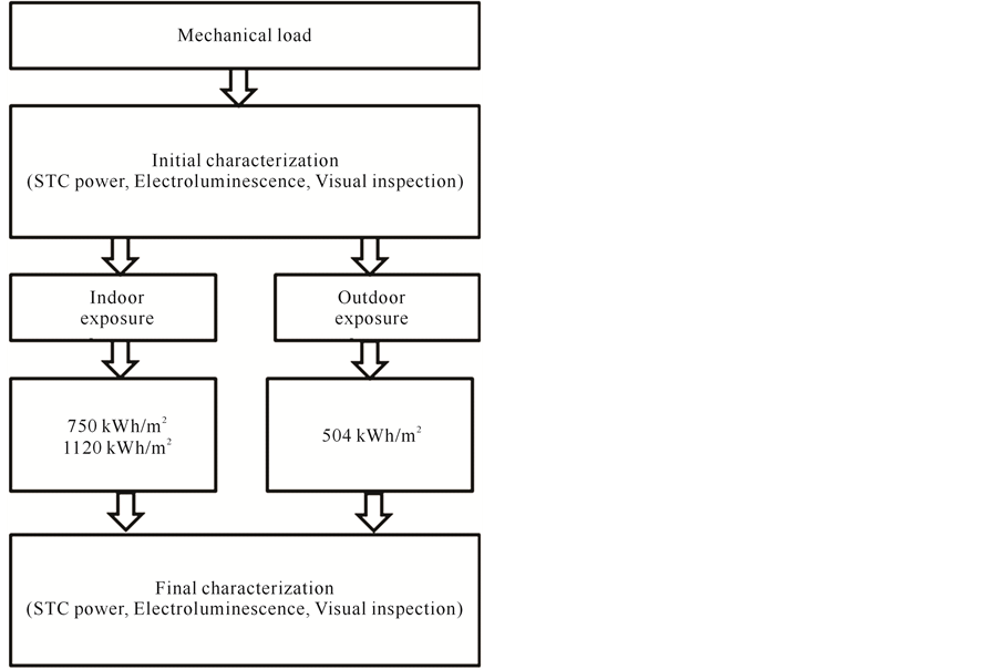
Figure 1. The snail trails testing flow chart.

Table 1. Module components for snail trails testing.
Further three pieces of 6 × 10 arrays photovoltaic modules were to be investigated long-term reliability impacted by snail trails. The long-term reliability test used 200 thermal cycles (TC200), 10 day humidity freeze (HF10) and 1000 hours damp heat (DH1000) according to IEC 61215 10.11, 10.12 and 10.13 standards, respectively. For IV characterization of these testing modules before and after the snail trail affects the Berger PSS30 flash tester [5] and a high resolution electroluminescence (EL) camera were used.
3. Results and Discussion
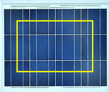
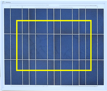
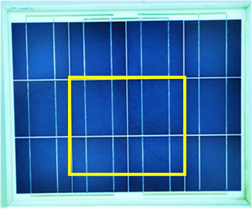
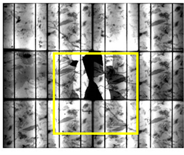
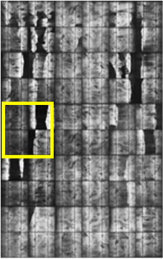
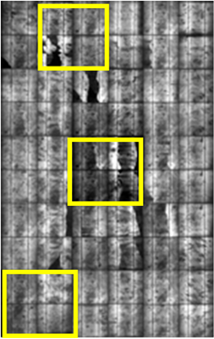
In this work we had successfully simulation the snail trails by our indoor method as shown in Figure 1. For risk analysis referring to snail trail effected modules it is not only to check power output, it is also essential to estimate to which extent further power degradation has to be expected within modules life time. These IV test results were shown in Table 2. In Table 2 the initial powers represent the power loss after mechanical loading test with respect to cell cracks. Next sequence light soaking was performed on modules entitled of No. 1 - No. 4, after irradiance accumulation to 1120 kW・h/m2 the modules of No. 1 and No. 2 power loss was 3.61% and 2.26% without significant discolorations for snail trails, respectively, pictures here were not shown. However the modules of No. 3 and No. 4 which appeared the clear discolorations under glass front sheet as shown in Figure 2(a) and Figure 2(b) yellow squares, the power loss were 1.49% and 1.20%, respectively. This is a very interested to these testing results. We speculated the EVA encapsulant splaying important roles than backsheets to trigger the effect. These discolorations had different opinions in issued papers [1] [2] [6] [7] . In our former studying we had verified the EVA film Mvolume resistivity, which had less one order than EVA film S [8] . The poor electric resistances may promote Ag ions migration and formed electrochemical corrosion [7] , hence caused the modules of No. 1 and No. 2 power loss more serious than modules of No. 3 and No. 4 without any discolorations. However inmodules of No. 3 and No. 4 power loss were not serious but appeared obvious snail trail discolorations. This may speculate to the EVA film S had extra antioxidant with respect to phosphorus [9] , it plays a reductant to result the fingers discoloration like snail trails. In order to compare No. 4 module we also used the same encapsulation conditions entitled No. 5 module to perform outdoor exposed testing. These results showed in Table 2 and Figure 3(a) and Figure 3(b) yellow squares. The No. 5 module had not only high power loss 16.84% but also snail trails. From these findings are suggesting additional power reducing processes not being correlated to the cell breakage but to electrochemical corrosion. The outdoor environment combined with high temperature and high humidity accelerated the Ag fingers corrosion to cause the No. 5 module power loss seriously. In Figure 3(b), the electroluminescence (EL) images showed the micro cracks which corresponding to snail trails formation. The snail trails following with cracks that induced a lot of moisture into module from back side and accelerated Ag ions migration to cause cell fingers discoloration and corrosion. In our studying the slight crack not caused power loss but serious cell cracks can cause the power loss seriously and more snail trails to be appearance.
To investigate power loss in the long term reliability of these PV modules impacted by snail trails in field, some accelerated aging tests were being conducted. In this paper we used three field-discolored snail trails modules. Testing items were 200 thermal cycles (TC200), 10 day humidity freeze (HF10) and 1000 hours damp heat (DH1000), respectively according to IEC 61215 10.11, 10.12 and 10.13 standards. Before testing we measured snail trail modules power loss after installation in field as shown in Table 3. The power loss had seriously degradation were 7%, 10.76% and 7.73%, respectively after 8 months field exposure. These over 5% power losses may come from light-induced degradation (LIP), cell cracks and corrosion. The extent of power degradation related to the snail trail issue mainly depends on the ratio of isolated crack cells during soldering, handling, shipping and installation. The Table 3 showed the power degradation in snail trail modules after accelerated aging
 (a) (b)
Figure 2. Photographs of modules with snail trails (a) No. 3 and (b) No. 4 module.
 (a) (b)
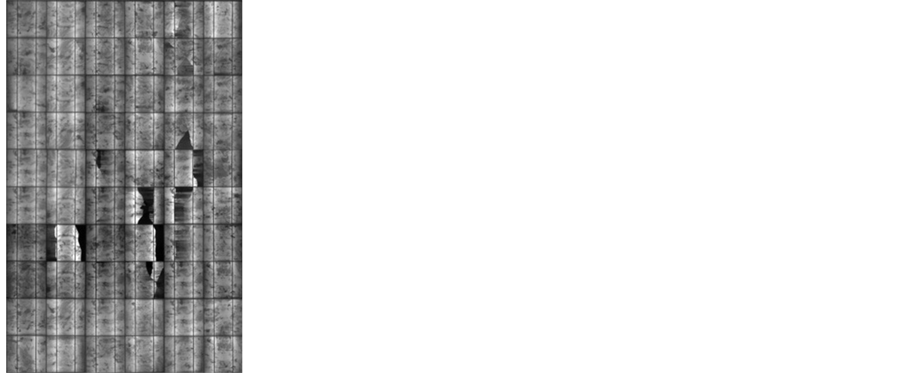
Figure 3. The correlation between (a) Visible optical features (snailtrails) and (b) Micro cracks visible in EL imagingafter No. 5 moduleoutdoor exposed testing.
Table 2. Current-voltage (I-V) results after light soaking at indoor and outdoor fields.
Table 3. Comparison the snail trail modules before and after the accelerated agingtests.
 (a) (b) (c)
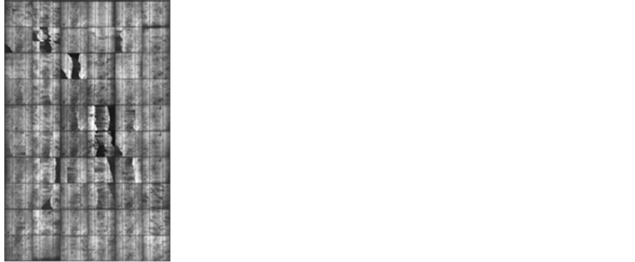
 (d) (e) (f)
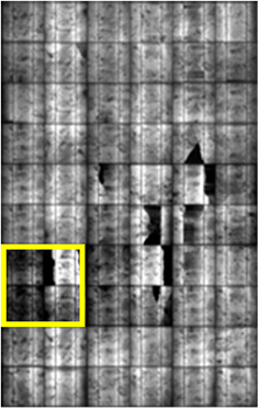
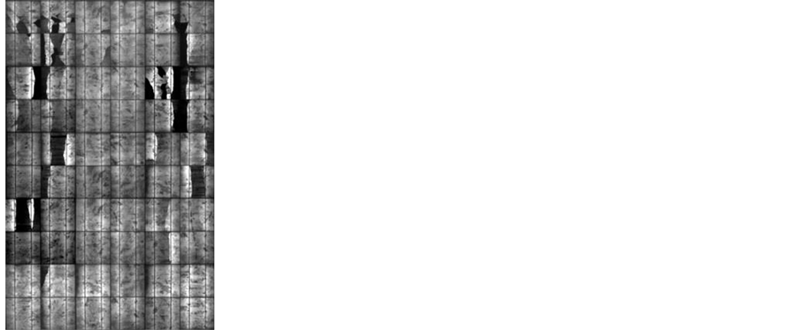
Figure 4. Comparison of snail trailsin field with EL images before and after accelerated aging tests (a) before TC200, (b) after TC200, (c) before HF 10, (d) after HF 10, (e) before DH1000 and (f) after DH1000.
tests were 8.38%, 11.36% and 9.54%, respectively. All snail trail modules decreased power within 2% during testing period and no discolored areas enlarged by our visual inspection. In here we can speculate the reactants such as EVA excessive antioxidant or peroxide exhausted and no further discoloration. A special phenomenon was observation in our long term 3000 hours damp heat test which original snail trails were disappearance (pictures here not shown) it like reversed process [10] . In Figure 4 the EL images showed cells micro cracks did not enlarge and no new micro defects were formed in the PV modules during the accelerated aging tests. From EL images showed little darken at former crack areas after these tests as shown in Figure 4(b), Figure 4(d) and Figure 4(f) yellow squares. There were corrosion formations to increase series resistance. In our results showed the power loss not serious after these accelerated aging tests. But not warranty the module performance correlated with cell cracks in the future. The cell cracks defects would need to be checked more detail to assure the PV module lifetime in future 25 years.
4. Conclusion
We were successful simulation snail trails in laboratory scale and commercial size. The appearance of snail trails discoloration had been visualized optical images and electroluminescence investigations. Our EL results showed the micro cracks following snail trails. The EVA encapsulant also played an important role for discoloration processes which not only by its physical (e.g. volume resistively) but also by its chemical additives. Furthermore, according to IEC 61215 accelerated aging testing shown these snail trails modules were power degradation within 2% and no discolored area enlargement after TC200, HF10 and DH aging tests. It meant that most power losses depended on cell cracks before snail trails appearance. According to our testing results, snail trails only the poor visual. The hide defect “cell cracks” are more aware. To minimize snail trails, the rigid quality control would be executed and therefore optimize the energy output of the PV module over 25 years lifetime.
Acknowledgements
The financial support provided by Bureau of Energy (contract No.: 104-D0304) is gratefully acknowledged.
Cite this paper
Han-ChangLiu,Chung-TengHuang,Wen-KueiLee,Shih-SiangYan,Fu-MingLin, (2015) A Defect Formation as Snail Trails in Photovoltaic Modules. Energy and Power Engineering,07,348-353. doi: 10.4236/epe.2015.78032
References
- 1. Berghold, J., Roericht, M., Bttcher, A., Wendlandt, S., Hanusch, M., Koch, S., Grunow, P. and Stegemann, B. (2012) Electrochemical Corrosion within Solar Panels. 27th European Photovoltaic Solar Energy Conference and Exhibition, Frankfurt, 3511-3517.
- 2. Richter, S., Werner, M., Swatek, S. and Hagendorf, C. (2012) Understanding the Snail Trail Effect in Silicon Solar Modules on Microstructural Scale. 27th European Photovoltaic Solar Energy Conference and Exhibition, Frankfurt, 3439-3441.
- 3. Rutschmann, I. (2012) Unlocking the Secret of Snail Trails. Photon International, 114-125.
- 4. http://www.onlinetes.com/tes0512-solar-industry-snail-trail.aspx
- 5. IEC (2007) Photovoltaic Devices-Solar Simulator Performance Requirements.
- 6. Peng, P., Hu, A.M., Zheng, W.D., Su, P., He, D., Oakes, K.D., Fu, A., Han, R.J., Lee, S.L., Tang, J. and Zhou, Y.N. (2012) Microscopy Study of Snail Trail Phenomenon on Photovoltaic Modules. RSC Advances, 2, 11359-11365.
http://dx.doi.org/10.1039/c2ra22280a - 7. Mon, G.R., Orehotsky, J., Ross, R.G. and Witla, G. (1984) Predicting Electrochemical Breakdown in Terrestrial Photovoltaic Modules. Proceedings of the 17th IEEE Photovoltaic Specialists Conference, Kissimmee, 1-4 May 1984, 337- 340.
- 8. Liu, H.C., Huang, C.T., Lee, W.K. and Lin, M.H. (2013) High Voltage Stress Impact on P Type Crystalline Silicon PV Module. Energy and Power Engineering, 5, 455-458.
http://dx.doi.org/10.4236/epe.2013.57049 - 9. Meyer, S., Timmel, S., Richter, S., Werne, M., Glser, M., Swatek, S., Braunb, U. and Hagendorf, C. (2014) Silver Nanoparticles Cause Snail Trails in Photovoltaic Modules. Solar Energy Materials & Solar Cells, 121, 171-175.
http://dx.doi.org/10.1016/j.solmat.2013.11.013 - 10. Pingel, S., Frank, O., Winkler, M., Daryan, S., Geipel, T., Hoehne, H. and Berghold, J. (2010) Potential Induced Degradation of Solar Cells and Panels. 35th IEEE Photovoltaic Specialists Conference (PVSC), 2817-2822.