World Journal of Mechanics
Vol. 3 No. 1 (2013) , Article ID: 27736 , 17 pages DOI:10.4236/wjm.2013.31002
Modeling Fiber Composites during the Cure Process for Piezoelectric Actuation*
Department of Mechanical Engineering, Mississippi State University, Starkville, USA
Email: darrylvmurray@gmail.com, myers@me.msstate.edu
Received November 10, 2012; revised December 11, 2012; accepted December 27, 2012
Keywords: Composite; Piezoelectric; Morphing; Modeling
ABSTRACT
Analytical, numerical, and experimental modeling methods are presented to predict deformation after the cure process of thin unsymmetric laminates for piezoelectric actuation. During fabrication, laminates deform to several post-cure room temperature shapes. Thin cross-ply laminates deform to a circular cylindrical post-cure shape while thicker laminates deform to a saddle shape. Post-cure shapes are dependent on ply orientation, thickness, and material properties. Because, CLT alone does not always predict the correct post-cure room temperature shape of the thin composite laminates, an extension of CLT with the Rayleigh-Ritz technique and potential energies are used to better predict these shapes. Finite element models are used to predict the post-cure room temperature shapes. Thin composite laminates are modeled coupling heat transfer and structural mechanics, which are necessary for modeling the cure process. Modeling the fabrication process captured important data such as residual stresses from the cure process, room temperature shapes, and bi-stability of the composite laminates. To validate these analytical and numerical results, experiments were conducted using macro-fiber composite (MFC) patches for morphing the laminates. The experimental piezoelectric morphing results relate well to analytical and numerical results.
1. Introduction
Smart material systems are vastly becoming an integral part in engineering applications. One of the phenomena used in smart material systems is piezoelectricity. Using unsymmetric bi-stable composites, piezoelectric effects can be implemented to achieve a snap through to the other stable shape of the composite [1]. Unsymmetric laminates are defined as laminates that are configured such that the geometric mid-plane is not a mirror image of the ply configurations above and below the mid-plane. This shape change caused by piezoelectric effects can be coupled with other domains and used as a sensor or actuator. To achieve bi-stability, a fabricated unsymmetric laminate is cured to a certain temperature then cooled to the operating or room temperature [1]. The curing process causes the laminate to deform due to the thermal strain gradient between the layers of the laminate. As an essential part of the piezoelectric system, the cure process and the resulting cured shapes are heavily investigated in the current paper.
After curing, a once flat laminate will deform into one of multiple shapes based on the laminate layup and the suggested cure temperature. Research and analysis are being done to predict the deformations and deflections of laminates. Dano and Hyer (2001) predicted the forces and moments that cause cure deformation using common theories based on displacements and strain fields [2]. Modeling three different lay-ups, the Rayleigh-Ritz method and the principal of work was used to determine these forces. Formulating equations for the first derivation of the strain energy, the reference or mid-plane strains and curvatures were approximated. These parameters were used to determine the in-plane and out-of-plane displacements using strain-displacement relationships. A system of equations was then used to approximate the work due to the thermal strains. The research continued on to applying moments to the laminate after the cure process to cause the laminate to snap through to the other stable shape. This research was done as an extension of Dano and Hyer (1996) previous work based on the same theories [3]. C. R. Bowen (2007) experimented with a cantilever beam of a [0/0/90/90] carbon fiber epoxy and an unsupported laminate of [0/90] for morphing testing and analysis [4]. The specimens were cured to a particular maximum temperature with constant pressure. Both specimens formed to one of the cylindrical shapes after the cure process. Piezoelectric actuation was then implemented using macro-fiber composite patches for electrical and mechanical coupling. Although the specific formulation of the cured deflections were not presented, the results were useful.
Hyer and Jilani (1998) presented a method for predicting the deformation of rectangular laminates cooled from the cure temperature to that of the room temperature [5]. The piezoceramic material named THUNDER was used for investigation. Due to the unsymmetric nature of the THUNDER system, deformation was observed as the system cooled from the cure temperature. After analyses were done, it was stated that the occurrence of one of the two stable shapes depends on the geometry of the laminate. This research consisted of also studying the issue of stability and what constitutes a laminate as being in one of the stable states.
The Classical lamination theory suggests that a laminate cooled from the cure temperature will achieve a saddle shape, the shape between the two stable shapes. This suggestion is not always correct. When cooled from the cure temperature, laminates can also attain one of the stable cylindrical shapes (concave up or down). M. Schlecht, K. Schulte, and Hyer (1995) extended the Classical lamination theory to approximate these shapes then compared these results to finite element analysis [6]. The results were used as parameters for the stress and strains during the snap through action to the other stable shape. It would seem that since geometry plays a role in the cured shape of the laminate, the ply orientation would also be a factor. D. N. Bettes, A. T. Salo, C. R. Bowen, and H. A. Kim (2010) investigates this along with other parameters effecting the cured shape [7].
Hyer also discusses the subject matter of stress analysis of fiber composites [8]. Hyer postulates many of the techniques used to determine stresses, strains, and displacements for a fiber composite including but not limited to these variables in reference to the cured shape. Numerous valuable techniques and assumptions can be found and have been used for this current research. Jones [9] also discusses the mechanics of composites used in this research and includes Hyer’s work on post cure shape change deformation. The importance of the approximation of the cure shape and the cure deformation is the cause of the abundance of research done within this area of unsymmetric laminates.
M. Gigliotti and M. R. Wisnom studied the curvature due to the cure process of an AS4/8552 [0/90] laminate [10]. The cure process was broken down in to three stages and further investigation was done. It was hypothesized that inconsistent thermal properties between plies, chemical shrinkage of resin/epoxy, interaction of the tool or mold, and a non-uniform cure temperature are the four thermal stress-strains mechanisms that cause stress in the laminate during the cure process.
The snap through phenomenon for piezoelectric systems are of interest and will be investigated in further research; the present paper focuses on the curing process and approximating the stresses, strains, and curvatures of the unsymmetric laminate during this process. As Schlecht and Schulte studied the thermal effects of the cure process on room-temperature laminates, this paper establishes analytical and numerical modeling for stress, strain, and curvature prediction after the cure process [6]. Using carbon pre-preg sheets, the plies are cut to the specific ply orientation. Then using an aluminum mold and a releasing agent, the laminate is placed in the mold inside a convection oven. During the cure process, there are four mechanisms that cause curvatures and deformation in the laminate [11]. The development of stress in the cured laminate has a significant effect on the piezoelectric actuation and analysis. There can be more advances on the prediction of these variables for better understanding for the application of smart material systems. To achieve optimum snap through with piezoelectric materials, whether sensing or actuators types, it is best that the laminate possess curvatures and strains necessary for particular applications [12-14].
M. W. Hyer also used strain energy theories and virtual work formulation to predict the post cure displacements and curvatures of the laminate [3,5]. These methods were evaluated using various types of lay-ups and cure temperatures. M. W. Hyer formulated the necessary equations to predict the variables then compared these values to experimental values of the same laminate. The most common lay-up was that of [0/90] T and it was used due to the simplicity of the governing equations. Libo Ren and Azar Parvizi-Majidi investigated the CLT and how the predictions of the post cure shape were not always correct [15]. Studying cross-ply shells, Ren and Parvizi modeled the cure shape using the Rayleigh-Ritz energy method. This method allowed consideration of geometric nonlinearity, a problem with the general CLT. M. Gigliotti and M. R. Wisnom along with K. Potter researched bifurcation of the saddle shape of a [0/90] composite [16]. During this study, the researchers observed the saddle shape was unstable compared to the other two cylindrical shapes. Using a numerical models, they compared the Rayleigh-Ritz method model to the numerical models.
As seen in the literature, bi-stability of the composite laminate is achieved during fabrication. After the cure process, multiple deformation shapes can be observed based on the ply orientation and material [9]. This deformation is due to the thermal strain gradient between the layers of the laminate and cure shrinkage during the cure process [10]. As an essential part of the smart material morphing system, the cure process and the resulting post-cure deformation shapes are heavily investigated. Thin unsymmetric composite laminates will deform to one of two circular cylindrical shapes, with the shape in between these two cylindrical shapes being unstable and called the saddle shape. Work has been done to show that the CLT can only predict that the post-cure room temperature shape of all thin composite laminates will be the saddle shape [17]. A Rayleigh-Ritz technique has been established and used here to study the post-cure deformation shapes. This paper presents the CLT first then builds upon it with the methods of strain energy and virtual work for approximations used by M. W. Hyer, Jones, and others to get better post-cure room temperature shape predictions. During the cure process, there are certain mechanisms which cause the displacement and shape change of the composite [18]. With these assumptions, the CLT is prone to error when determining the post-cure room temperature shape. The numerical models have the capabilities to couple thermal, electrical, and mechanical domains and allows user defined equation integration. This phase of research entails modeling the cure process, which is used to more accurately characterize the piezoelectric attachment and actuation in the numerical models. To validate the techniques and methods used, the analytical and numerical models are compared to experimental results.
2. Analytically Modeling the Cure Process
The fabrication and cure process of unsymmetric laminates are essential elements of the smart material morphing structure. Models were developed to achieve a better understanding of these processes for piezoelectric actuation. An analytical model is presented first to predict the post-cure shape and deformation. The analytical model was based on both Hyer’s and Vizzini’s composite material work [3,19,20]. Numerical analysis was done to compare to the analytical results, and is presented following the analytical models. Multi-physics Finite Element Models were created for numerical modeling of both the fabrication process and piezoelectric actuation [21]. Experimental setup and procedures for fabrication and the cure process are then explained. Analytical, numerical, and experimental results will be shown. A post-cure shape deformation comparison between the models will be shown in later sections.
2.1. Classical Lamination Theory
AS4 carbon fiber pre-impregnated laminae are used for the composite laminates of this study. Due to the thickness of the carbon fiber pre-pregs, the laminates in this study are classified as thin composite laminates where the thickness to length ratio is less than $\frac{1}{20}$. This ratio is important for post-cure deformation shapes, thin laminates will deform to a circular cylindrical shape whereas a thicker laminate will deform to that of the saddle shape. The first model was done with the CLT for composite laminates. For CLT analysis, the following key assumptions of the material are made:
• assume smeared properties through thickness;
• assume perfectly bonded laminae with no defects;
• assume zero bond line thickness between plies (no epoxy between plies);
• assume Kirchhoffs hypothesis is valid; plane sections remain planar and perpendicular sections remain perpendicular.
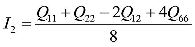
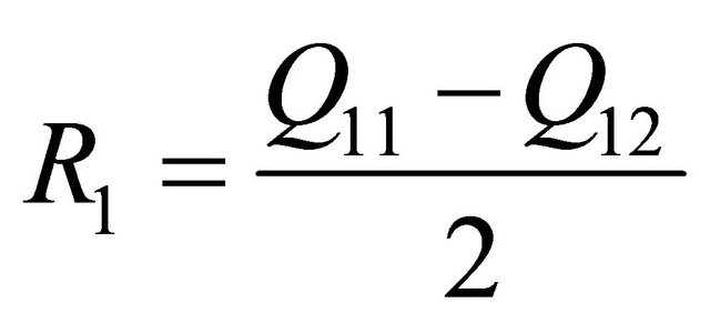
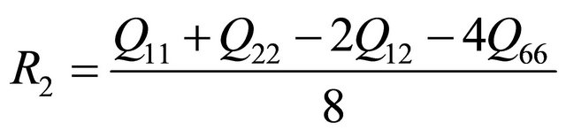
The first assumption states that the individual fibers of the laminae are homogeneous, not varying with direction. The second and third assumptions are made to eliminate any complications with bonding the laminate. The models of the laminate are assumed to be perfectly bonded with no epoxy layer between the plies. The fourth assumption is made in relation to Kirchhoffs hypothesis. This assumptions states that the strain is linear through the thickness of the laminate. The laminate is then treated as an orthotropic material with three planes x, y, and z (also known as 1, 2, and 3). Treating the laminate as an orthotropic material, nine engineering constants of the material are required including Youngs modulus, Poisson ratio, and shear modulus of the material one in each directional plane. These constants are then used to determine the reduced material stiffnesses of the laminate [20]. In order to observe how material stiffness relates to each individual lamina with a specified orientation, the stressstrain relations need to be transformed. Using a method on invariants, the lamina stress-strain relations can be determined for an arbitrary orientation. In terms of the reduced stiffnesses, these invariants can be calculated
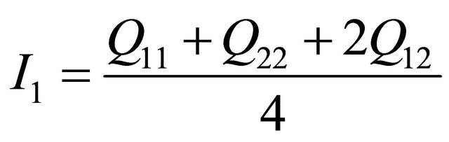 (1)
(1)
 (2)
(2)
 (3)
(3)
 (4)
(4)
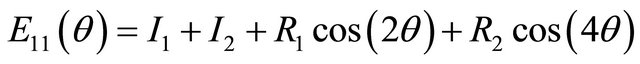
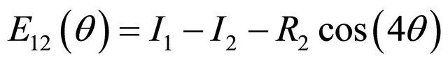
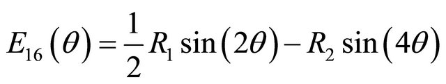
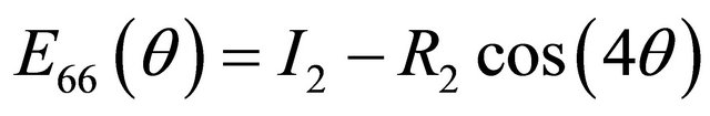
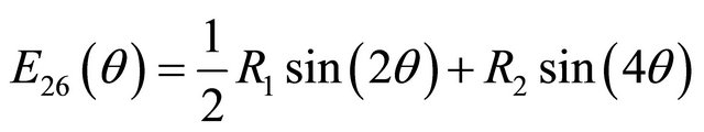
where Qij are the reduced material stiffnesses [9]. Using these invariants, the transformed reduced stiffness tensor can now be found:
 (5)
(5)
 (6)
(6)
 (7)
(7)
 (8)
(8)
 (9)
(9)
 (10)
(10)
where θ is the arbitrary ply orientation. The next step in the analysis is to calculate the forces and moments that occur during the cure process. In order to determine these resultant forces and moments the extensional, bending-extension coupling, and the bending stiffness tensors also named the ABD matrix, must be calculated. Using the rotated stiffness tensor equations and the middle surface lamina thickness, the ABD matrix can be determined for each direction of the laminate [9]. The B tensor component of the ABD matrix, the bending-extension coupling stiffness, implies that if the composite is pulled a bending and/or twisting reaction of the composite must occur also. For the thin cross-ply unsymmetric composites, this bend/twist coupling is not expected to occur. Treating the laminate as an orthotropic material comes from the the Dij component of the ABD matrix which is the bending stiffness of the laminate. If D16 =D26 = 0, then this assumption can be made. Unsymmetric laminates contain this type of coupling stiffness while symmetric laminates do not. The force and moment constitutive equations are given by
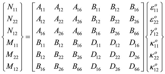 (11)
(11)
where N and M are the forces and moments. To calculate these strains and curvatures values, the ABD matrix can be inverted to solve for the desired variables. If the forces and moments were to be determined and the strains and curvatures were known, the simple calculation can be done with the matrices. Continuing the CLT, the laminate is treated as orthotropic material to equate the thermal strains to the coefficients of thermal expansion multiplied by the thermal gradient. The residual stresses and strains arising from the cure process can then be found [20].
2.2. Rayleigh-Ritz Technique
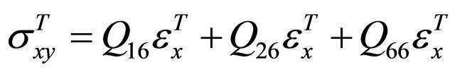
The CLT predicts a saddle shape will occur each time a thin unsymmetric laminate cools from the elevated cure temperature to room temperature. This is due to the failure to capture reference strain due to the large out-ofplane deformations as the laminate is cooled. The Rayleigh-Ritz technique accounts for the large out-of-plane deformations arising from the room temperature cooling. The maximum states of the potential energy are the unstable equilibrium conditions of the laminate. The minimum states of the potential energy are the conditions needed to characterize the deformations of the laminate cooling to room temperature. Using the same engineering constants, mentioned earlier, the reduced stiffnesses of the laminate are found. The coefficients of thermal expansion are also transformed to the ply orientation not aligned in the principal axis. The process is continued to using the method of invariants mentioned in the earlier section to determine the reduced stiffnesses of the laminate. The thermal strains and stresses are then evaluated using the following equations:
 (12)
(12)
 (13)
(13)
 (14)
(14)
where the thermal strains, εT, are given by:
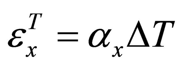 (15)
(15)
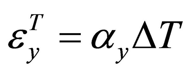 (16)
(16)
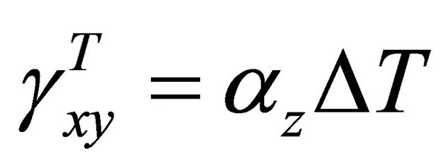 (17)
(17)
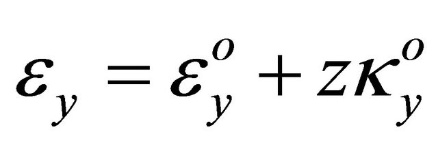
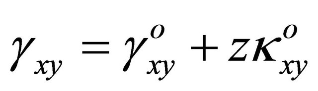
where αi are the coefficients of thermal expansion. The middle surface strains and curvatures can then be approximated. Where uo, vo, and wo are the displacement fields:
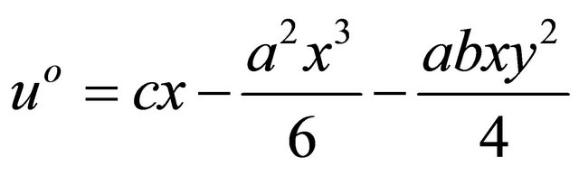 (18)
(18)
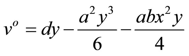 (19)
(19)
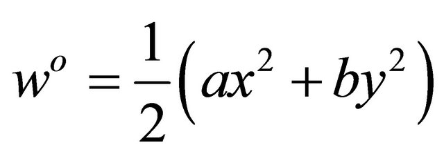 (20)
(20)
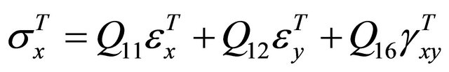
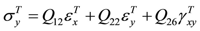
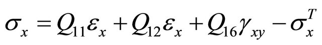
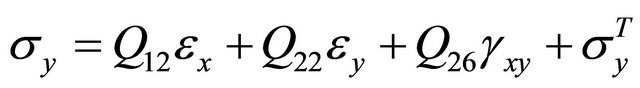
The stresses and strains are then approximated using
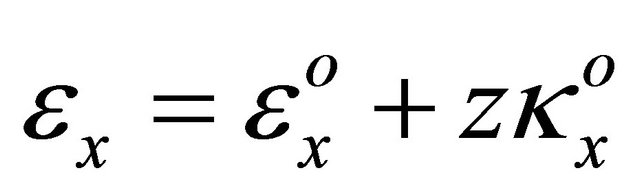 (21)
(21)
 (22)
(22)
 (23)
(23)
 (24)
(24)
 (25)
(25)
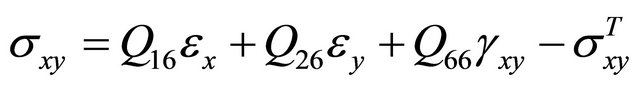 (26)
(26)
The post-cure room temperature shape can then be modeled. This step does not include bonding the MFC actuator, therefore only thermal effects are accounted for. The strain energy or total potential energy is given by:
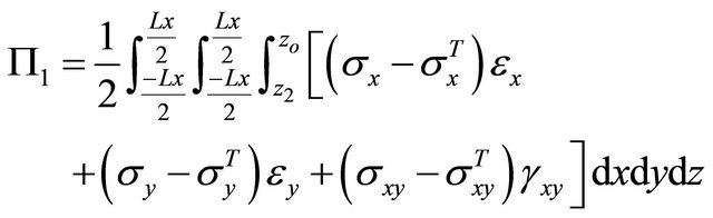 (27)
(27)
Carrying out the integrations in equation 27, the potential energy is then reduced to an algebraic equation in terms of the coefficients a, b, c, and d. Once the integrations are computed, Equation (27) will show that the potential energy is also in terms of material properties and geometries of the laminate. These coefficients are then determined by solving the nonlinear algebraic equations that is reduced from equating to zero the first variation of the potential energy with respect to the coefficients,
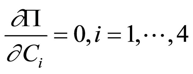 (28)
(28)
where C is a, b, c, and d. The undetermined coefficients were found using Newton’s iterative method. These solutions relate to the equilibrium shapes of the cooled room temperature laminate. To check stability of the solution for the laminate, the second variation of the potential energy must be positive definite.
The following is an example of the results found for the analytical methods mentioned for the post-cure room temperature shapes of the laminates. Table 1 shows the material properties of the carbon fiber used.
The laminates studied were [0/90], [02/902], [0/45], and [45/90] square and rectangular laminates. When cooling to room temperature, the cross-ply laminates will deform to one of three possible equilibrium shapes. Two being stable cylindrical shapes and one being the unstable saddle shape, the shape between the two cylindrical shapes. After analytical formulation, these equilibrium shapes can be predicted and are shown in the meshes of Figure 1 for the [0/90] laminate.
Table 1. Material properties of AS4 carbon fiber.
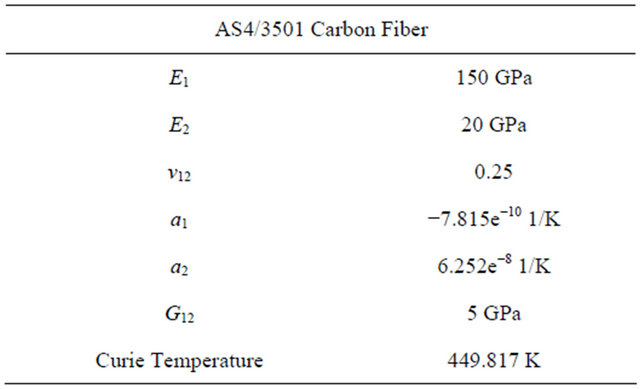
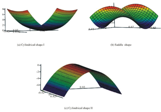
Figure 1. [0/90] Cooled room temperature shapes.
As seen in plot two of Figure 1, the saddle shape can be referred to as the shape between the two cylindrical shapes. For the simple cross-ply laminates, this shape should not occur after cooling to room temperature. The different orthogonal cylindrical curvatures can be seen and compared in plots one and three. For the [0/90] laminate, the expected post-cure deformation shape is the shape in plot one. After piezoelectric actuation, the [0/90] laminate should snap through to the second cylindrical shape two, shown in plot three of Figure 1. The transverse displacement after the curing process was also studied. This was done to investigate the curvatures of both the post-cure shape and the later piezoelectric actuated shapes. For the first cylindrical shape, a (expected shape after curing), the transverse curvature is along side length Lx. This is the curvature for the ideal situation. The third plot shows the second room temperature cylindrical shape of the [0/90] laminate.
Next, predictions can be made for the [02/902] laminate using the same techniques as described earlier. With more plies than the [0/90] laminate, the curvature is expected to be different due to the increase of plies. The transverse curvature for the first cylindrical shape (expected shape after curing) of the [02/902] laminate is expected to be along the length of side $L_y$. When compared with the [0/90] laminate this curvature is in opposite the direction along the other axis. The equilibrium shapes, shown as meshes, of the [02/902] laminate in Figure 2 confirms the different post-cure shape of the laminates.
The first plot (a) in Figure 2 is the expected post-cure shape of the [02/902] laminate. Plot b represents the shape between the two cylindrical shapes, the saddle shape. Plot c shows the expected actuated displacement shape of the [02/902] laminate.
The [0/45] laminate was modeled using the RayleighRitz technique as described above. With a ply orientation at 45˚, it is expected that the laminate will not deform to one of the equilibrium cylindrical stable shapes. Instead, the [0/45] laminate should deform to the saddle shape. As research shows, this shape is unstable compared to the simple cross-ply laminates. The stability is determined by the second variation of the total potential energy, or the second derivative of the Jacobian matrix. If this matrix is positive definite, which confirms that the equilibrium solution is stable. As shown in Figure 3, the analytical models predicted the post-cure shape of the [0/45] laminate will deform to the saddle shape. The meshes in Figure 3 may seem flat when compared to the simple cross-ply laminates, but that is due to the instability of the laminate.
The curvature of the [0/45] laminate is along both the x and y axis. This is a characteristic of the saddle shape. After fabrication, the [0/45] laminate should deform to this saddle shape. For piezoelectric actuation the [0/45] laminate is still going to snap through to another saddle shape (shown in later chapters), but unlike the simple
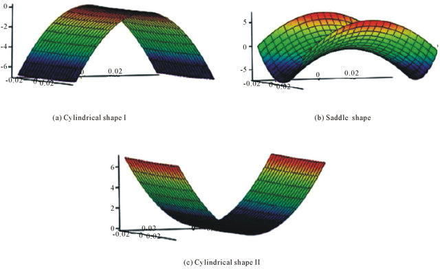
Figure 2. [02/902] Cooled room temperature shapes.
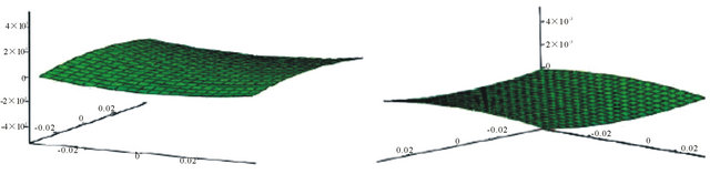
Figure 3. [0/45] Cooled room temperature shapes.
cross-ply laminates, due to the instability of the [0/45] laminate removal of the snap through force will cause the laminate to snap back to its original shape shown in Figure 3. These analytical results can now be used as predictions of the post-cure room temperature shapes as well as models to help accurately capture the effects of the piezoelectric actuation models. Comparisons were made to the numerical models and the experimental results.
3. Numerical Modeling the Cure Process
Multi-physics numerical FEA models were used to compare analytical models and experimental results. The present models required implementing the Thermal-Structural Interaction mode, which couples both, the structural mechanics and the heat transfer modules. The analysis type of the stress-strain and the heat transfer modules were chosen as static and transient types respectively. Due to the small thicknesses of the laminates studied, models were done using linear and quadratic mesh element types.
3.1. Initial Setup
The Thermal-Structural interaction mode allowed for including thermal expansion due to the coefficients of thermal expansion(CTE) during the cure process. The CTE’s along with geometry and other material parameters, play key roles during the heating and cooling of the laminate. In numerical model 3-D space, new coordinate systems are needed to specify certain fiber orientations for plies not oriented in the global or principal material axes. This feature is done by rotating the global coordinate system from the original x, y, z axis to the angle needed for the specific ply. Allowing $0^o$ to represent the default or global coordinate system (no need to change coordinate system if ply is oriented at $0^o$), the remaining plies coordinate systems can be changed using the consecutive rotation axes option. After the laminate is drawn with the specified dimensions, the material properties and conditions can be specified in the structural mechanics subdomain settings of the model. The heat transfer sub-domain settings controls the heat source and the thermal properties of the laminate. The structural domain settings control the material properties of the laminate, including the fiber orientation.
The laminate model was treated as an orthotropic material as stated earlier. In these settings, the necessary engineering constants along with the selection of the global coordinate system and specified created coordinate systems can be entered. The initial pressure of the laminate can be selected. An initial pressure was used to model the mold pressing the laminate flat during the heating of the laminate. Similar to the sub-domain settings, there are separate boundary condition settings for the structural application and the heat transfer application. Modeling free thermal expansion, there were no constraints on the boundaries or edges of the laminate. Compared with the analytical model, this assumption can be made due to the absence of external loads during the cooling of the laminate to room temperature. When solving the model, the solver parameters are important for accuracy and solver convergence. For the structural application mode, the solver was chosen based on the static analysis nature of the problem. This analysis type differs from the heat transfer application mode, however. For the heat transfer application mode, the analysis was chosen to be transient based on the steps of the curing process. Therefore, the analysis type needed to couple both the static and transient nature of the curing process.
3.2. Coupling Structural Mechanics and Heat Transfer
The numerical analysis allowed for more complex lamina behavior than the CLT assumptions used in the analytical modeling. For the structural mechanic analysis mode of the numerical modeling, a few important equations were used to define the domain of the laminate. Using the solid, stress-strain application for 3-D modeling, the straindisplacement relationship equations were specified as follows:
 (29)
(29)
 (30)
(30)
 (31)
(31)
 (32)
(32)
 (33)
(33)
 (34)
(34)
The stress-strain relation of the numerical analysis is given by the generalized Hooke’s Law formulation:
 (35)
(35)
where D is the stiffness matrix of the material. The Structural Mechanics mode is based on the weak formulation of equilibrium equations in the global stress components. For 3-D models, the equilibrium equation is represented by:
 (36)
(36)
where ![]() is the stress tensor and F is the volume or body forces [21].
is the stress tensor and F is the volume or body forces [21].
The sub-domain setting for the heat transfer mode was specified using Fourier’s law:
 (37)
(37)
where T is the temperature being measured at that instant, Q is the heat source, and k is the thermal conductivity. Specifying the heat transfer boundary equation using the heat flux equation,
 (38)
(38)
where qo is the inward heat flux of the composite being modeled, h is the heat transfer coefficient, Tinf is the external temperature, Const is the numerical constant for heat transfer relations, and Tamb is the ambient temperature. The heat transfer boundary equation is a form of the heat convection equation. The second half of the heat transfer boundary equation is the heat transfer due to radiation. Although shown, it was not used in the models. The equations in this section are all derived or are a form of the same analytical equations used in the numerical analysis. Using the same material properties as in Table 1, the laminates were modeled and the post-cure room temperature shapes were predicted.
Applying an initial pressure of 5.861 × 10⁵ Pa to the laminate models the press applied from the mold during the heating of the laminate. The laminate is then heated to 449.817 K then cooled to room temperature, 296.483 K. Figure 4 shows the numerical solutions of the postcure room temperature shape for the [0/90] rectangular and square laminates. It is seen that for both [0/90] laminate geometries, the symmetric circular transverse curvature is in the negative z-direction. This curvature can be seen in the first plot of Figure 4 along the x-direction and along the y-direction in the second plot.
The [0/90] laminate was modeled with a total thickness of 0.36002 mm with square length of 76.2 mm and rectangular lengths of Lx = 61 mm and Ly = 120 mm which classified the laminates as thin laminates. In addition to being thin laminates, they were simple cross-ply laminates therefore the saddle shape is not present here. Increasing the number of plies to a [02/902] laminate, different cylindrical room temperature shapes are observed. Figure 5 is the numerical solution of the room temperature shape of the [02/902] laminate. The [02/902] laminate was modeled at 0.72004 mm total thickness. The lengths were the same as the [0/90] laminate. Therefore the saddle shape is not seen here. For the [02/902] laminate, the symmetric circular transverse curvature is in the positive z-direction. This curvature is seen in the first and second plot of Figure 5 along the y-direction.
For laminates that are not simple cross-ply laminates, a saddle shape as the room temperature post-cure shape is expected. Experimental and analytical work [6] has been
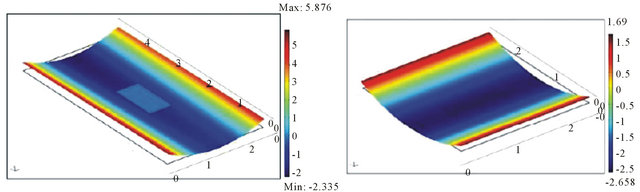
Figure 4. Rectangular and square [0/90] cylindrical shape I.
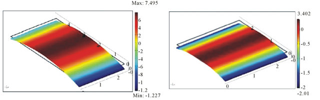
Figure 5. Rectangular and square [02/902] cylindrical shape I.
done to better understand the saddle shape and the instability of the laminate. The simple cross-ply laminates deform while cooling to room temperature to a symmetric circular shape. This is seen in the numerical solutions above. More complex laminates will deform unsymmetrically with a twist curvature similar to the saddle shape. This twist curvature develops as the laminate cools to room temperature. Applying a force to this saddle shape will cause deformation, but unlike the simple cross-ply laminates, removal of the snap through force will cause the laminate to return to its original shape. This classifies the laminate in the saddle shape as unstable. For this study, [0/45] and [45/90] were used for experimentation. Using the same parameters as the simple cross-ply laminates, the [0/45] laminates were modeled.
Figure 6 shows the rectangular and square [0/45] laminate at room temperature. The saddle shape is observed due to the 45˚ ply. The twist curvature which characterizes the saddle shape is seen in all three plots. For the rectangular [0/45] laminate in plot 1, two edges deform upward in the positive z-direction while the other two edges deform downward in the negative z-direction.
4. Experimental Fabrication and Results
4.1. Experimental Fabrication
A standard hand lay-up procedure was used to stack the plies of the laminate. Both square and rectangular laminates were fabricated to better understand the role of the material properties and geometry in piezoelectric actuation. A mold was designed to press the laminate flat while heating to the cure temperature. A convection oven at Mississippi State University Raspet Flight Research Laboratory was used for curing the composite laminates. The mold held the composite laminate flat while in the oven at a cure temperature of 449.817 K. Unsymmetric laminates and the snap through phenomenon work best when the laminate can be classified as a thin laminate.
After removal of the mold from the oven, the press is released allowing the laminate to deform freely. Thin laminates, where the length and width are large compared to the thickness, will deform to one of two cylindrical shapes as discussed earlier [8]. The laminate is then left over night to complete cooling. Figure 7 shows both the [0/90] and [02/902] laminate after the cure process. The circular curvature seen in Figure 7 for the [0/90] laminate and the [02/902] is similar to the prediction of the analytical and numerical models.
The post-cure transverse curvature in the [02/902] is greater than the curvature of the [0/90] laminate. This is possible due to the increase of the number of plies in the laminate. Although the transverse curvature is greater, with more plies the laminate becomes stiffer, therefore making it more difficult to apply force for snap through without damaging the laminate.
The next composites fabricated were the laminates that were not classified as cross-ply laminate. These laminates, as discussed earlier, is expected to deform to a saddle shape. The twist curvature that arose from the cooling of the laminate is seen in both the [0/45] and [45/90] laminates in Figure 8. The curvature is similar to numerical models presented earlier.
For comparisons seen in later sections, the transverse displacement of the deformed laminates were measured. Due to the symmetric curvature of the simple cross-ply laminates, [0n/90n] where n is the number of plies, this symmetric cylindrical shape can be measured using a FARO gage Coordinate-measuring machine (CMM). The CMM establishes a coordinate system for the laminate. This coordinate system is then used to measure the deformation and mesh the post-cure room temperature laminate. The difference between the post-cure room temperature symmetries of the cross-ply laminates and other laminates can now visibly be seen. For the cross-ply laminates, the post-cure room temperature curvatures were symmetric as expected. For the [0/45] and [45/90] laminates, the curvature is not symmetric as the cross-ply laminates. This was expected and predicted due to the
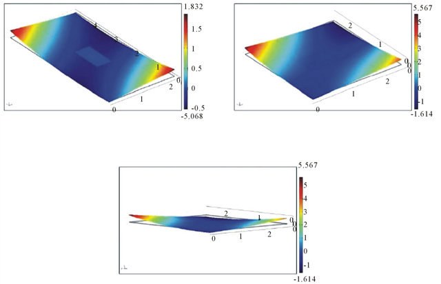
Figure 6. Rectangular and square [0/45] shape I.
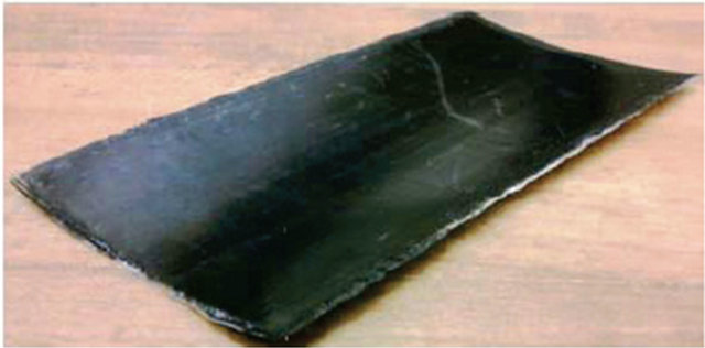
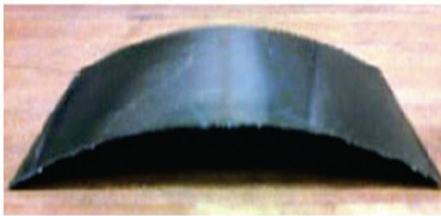
Figure 7. Cured room temperature shapes of [0/90] and [02/902].
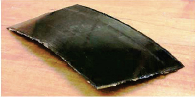

Figure 8. Cured room temperature shapes of [0/45] and [45/90].
ply orientation of the laminates. This saddle shape when compared to the cylindrical shapes of the cross-ply laminates is classified as an unstable shape. Applying a force to the post-cure room temperature shapes causes the laminates to snap through to another shape. For the crossply laminates this shape is the second cylindrical shape seen in previous sections. After snap through, this shape remains upon removal of the snap through force, therefore being a stable shape. For the laminates not classified as cross-ply laminates, the laminate will snap back to its original (post-cure room temperature) shape upon removal of the snap through force. Therefore these laminates are unstable.
4.2. Experimental Comparisons
For the analytical method, the Rayleigh-Ritz technique along with the total potential energy was used to predict the post-cure shape of the thin laminates. After fabrication, the profile of the laminates were measured using the CMM gage instrument. This instrument provided a coordinate system and data points for the deformed laminate, which provided meshes of the laminates. The data points can also be compared to the transverse post-cure curvatures of the analytical and numerical models. Because laminates wet thin and the CMM required contact, laminates were easily moved vertically by the gage arm of the CMM. When collecting the data points of the post-cure shape, the CMM arm would forcefully displace the laminate up or down. This caused a few errors when plotting the data points of the laminates from the CMM instrument. Laminates were taped to the measurement table to increase stiffness and minimize deflection to the the CMM. Although this provided better control of the arm and laminates, the error was still evident as the CMM arm moved across the laminate.
The post-cure fabrication results of the [0/90] rectangular laminate is shown in Figure 9 below.
The comparisons for the experimental results and the numerical model are shown in Figure 9. The solid black line represents the experimental results and the red traingles represent the numerical model. In plot one, the curvature is given along the x-axis from end to end. The coordinate system here places the origin at the edge of the laminate. Although reasonably close, the error seen is due to the probe of the FARO CMM arm. The same results can be shown for the square [0/90] laminate in Figure 10. As expected, the post-cure curvatures for the [0/90] laminate are in the negative z-direction along the x-axis. This post-cure curvature is expected to be opposite for the [02/902] laminates.
The [02/902] laminates have been compared similar to the [0/90] laminates. As seen in other sections, the postcure curvature of the [02/902] laminates are in the positive z-direction along the y-axis. The different curvature of the [02/902] and the [0/90] laminate is due to the more dominate 90˚ plies. While fabricating the laminates, it
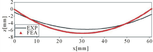
Figure 9. Rectangular [0/90] post-cure room temperature displacement.
was observed after cutting to size, that the 90˚ carbon pre-preg would start to deform to this shape when left alone. Therefore, during cooling of the [02/902] laminates this deformation is to be expected. Similar to the [0/90] laminate, the numerical model will be shown as red triangles on the plot while the experimental results will be represented by solid black lines in Figure 11.
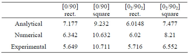
The maximum post-cure curvatures for the simple cross-ply laminates are shown in Table 2. The laminates not classified as the simple cross-ply laminates could not be measured with the FARO CMM gage due to the unsymmetric post-cure curvature. Therefore the other laminates were investigated by the use of numerical models and experimentation. The analytical and numerical models can now serve as preliminary models necessary for piezoelectric actuation.
The comparisons of the [02/902] laminate for the numerical model and the experimental results are shown in plot one of Figure 11. The curvature shows that the maximum magnitude for the post-cure transverse displacement is going to occur at the center laminate, approximately by 7.5 mm. The same comparisons are made for the square [02/902] laminate.
5. Piezoelectric Actuation
Using the results of the sequential models of the fabrication process, the effects of piezoelectric actuation were
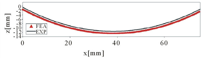
Figure 10. Square [0/90] post-cure room temperature displacement.
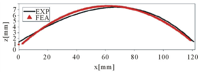
Figure 11. Rectangular [02/902] post-cure room temperature displacement.
Table 2. Maximum post-cure displacement curvatures (mm).
captured. These preliminary models enhance the knowledge of the key parameters needed for piezoelectric actuation. The MFC actuator used for experimentation is distributed by Smart Material Corporation. The MFC was invented by NASA in 1996 and since then has been continued to be improved for many applications. The piezoelectric material of the MFC actuator are r piezoceramic rods of the actuator [1]. These rods are sandwiched between electrodes and polyimide film as shown in Figure 14. The electrodes are in an interdigitated pattern allowing for direct application of the a voltage to the rods, which is the converse piezoelectric effect. Once the voltage is applied, the actuator will elongate or deform. This system enables in-plane poling and actuation, both which are used for this research. The operation mode used for experimentation was the d33 operating mode. This mode elongates the rods when a voltage is applied. The tensor notation for the operation mode can be broken down to better understand the proper applications and differences between other operation modes. The first variable, 3, represents the axis of polarization for the material. This direction 3, is through the thickness of the material also known as the z-direction if in x, y, z coordinates. Making the 1 and 2 directions align in the plane of the piezoelectric material. The second variable, 3, represents the direction of which the state of the piezoelectric material should be analyzed [22]. With the d33 operation mode and the assumption of free strain, the constitutive equations are reduced. Free strain is the strain produced in the piezoelectric material when there is no resistive stress on the material. Piezoelectric actuation will be shown for the [0/90] laminates.
5.1. Analytical Morphing Models
For piezoelectric analysis, the plates or in this case MFC actuators, were classified as thin plates. Thin plates are those with a ratio of thickness to length less than 1/20. This allows the complex three-dimensional problem to be reduced to a problem in two dimensions [22]. Using the same assumptions of the classical plate theory, the thin plate is now classified as a plane stress problem. The analysis implements the total potential energy approach similar to the post-cure shape analytical work. The Ritz method is used for the variational principal solution and is reduced to a set of linearly independent equations by an assumed form of generalized coordinates. This same procedure was done in previous sections for modeling the cure process. The post-cure room temperature shapes in previous sections had to be accounted for in piezoelectric analysis. When using the total potential energy to model the post-cure shapes, the driving force was the heat transfer taking place. Now for piezoelectric analysis, the driving force will be piezoelectricity. The total potential energy in response to the MFC actuation is given by:
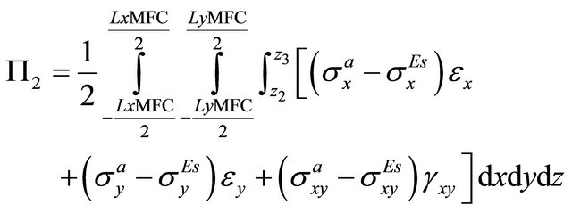 (39)
(39)
where 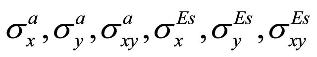 are the stresses and
 and
and  are the strain strains in the MFC actuator which include the stresses induced by bonding the MFC actuator to the laminate [23]. The total potential energy for the actuation of the laminate, taking the postcure deformation into account is then given as:
 (40)
(40)
Using the same techniques, the undetermined coefficients a, b, c, and d can be found by minimizing the total potential energy. Thus giving the actuated shapes for the MFC actuator and laminate.
For the post-cure [0/90] laminate, the curvature was in the negative z-direction along the x axis. For the cylindrical shape II, the curvature is expected to be in the positive z-direction along the y axis (this would be known as the orthogonal cylindrical shape). The postcure shape (cylindrical shape I) of the [02/902] laminate has transverse curvature in the positive z-direction along the yaxis. The orthogonal cylindrical shape to the deformed post-cure shape of the [02/902] laminate would have curvature in the negative z-direction along the x-axis.
As shown in Figure 12, the actuated deformation obtained from the total potential energy method predicted the [0/90] laminate to deform in the positive z-direction. The expected curvature for the [02/902] laminate has also occurred.
5.2. Actuation Modeling
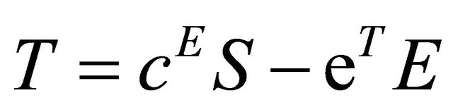
After the curing process is simulated, the same models can be used to model the piezoelectric actuation. Running the structural mechanics and heat transfer modules together, gave the post-cure room temperature shapes of the cross-ply laminates. Using these existing models, the 3D piezoelectric solid module was added. This allowed for the same post-cure curvature (same geometries from cure process models) to be used for modeling piezoelectric actuation. The same element types were used as in the fabrication models. After drawing the rectangular 27.9 × 13.995 mm MFC actuator at the center of the laminate on the first ply, the laminate and actuator was bonded to the laminate by creating a contact pair between the bottom surface of the MFC actuator and the top surface of the laminate. This was done to make the MFC actuator and laminate active in one domain. The actual MFC actuator has piezoelectric fibers along the length of the actuator, which corresponds to the zero direction. Therefore, for the numerical models, the MFC actuator was bonded to the laminate according to the direction of the first ply. Using the same structural mechanics domain settings from the cure process models, the ply orientation, thickness, and material are recalled for the 3D piezoelectric solid module. These models implement applying the voltage to the MFC actuator using the following piezoelectric equations in the stress-strain form.
 (41)
(41)
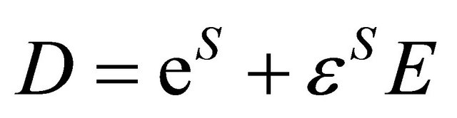 (42)
(42)
where the variables T, c, E, S, e, D, εS are the stress, Young’s modulus, electric field, strain, piezoelectric constant, electric displacement, and the permittivity of the piezoelectric material. The Piezoelectric Decoupled, anisotropic model was used for the actuation models. Using this modeling, the full six-by-six elasticity matrix was defined and the boundary conditions are established [21]. Figure 13 shows the simulation results of the [0/90] laminate post-cure and post actuation where you can see the change in shape direction after the MFC has been actuated.
5.3. Actuation Experiments
The bonding process done in this research was the process suggested by the Smart Material Corp. For experimental uses, a LabView chassis was used to control the system. For experimentation, the programming voltage was increased from zero by 0.02 V DC per 45 seconds until snap through was observed. An experimental snapthrough laminate is shown in Figure 14 and the experimental set-up is shown in Figure 15.
After snap through of the laminate to the orthogonal cylindrical shape II, the voltage load is removed to assure the cylindrical shape II is stable. If the shape was unstable, removing the load (voltage) would cause the laminate to snap back to cylindrical shape I. In Figure 16, the transverse actuated displacement is presented in the second picture.
After running the experimentation process a number of times and experiencing snap through, it was observed for the rectangular [0/90] laminate, an estimated voltage at snap through was 391 V DC. This voltage magnitude was then used in the numerical model to get better results for comparisons. Comparing to the analytical predictions of the post-cure and actuated shape, the experimental results are similar. The same procedure was done with the square
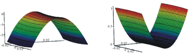
Figure 12. Predicted actuated shapes, cylindrical shape II for [0/90] and [02/902].
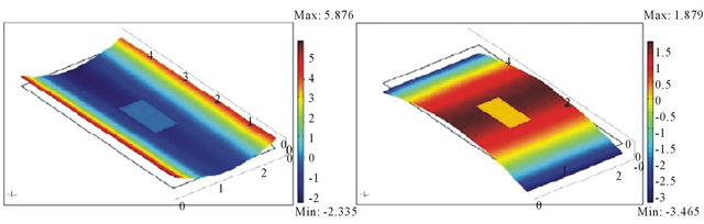
Figure 13. Rectangular [0/90] room temperature shape vs actuated shape.
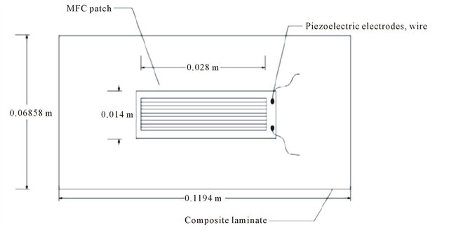
Figure 14. Experimental MFC patch on rectangular laminate.
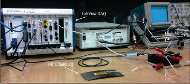
Figure 15. Experimental set-up.
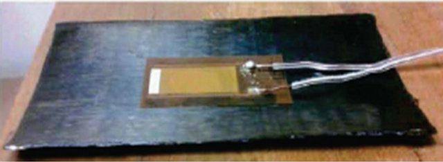
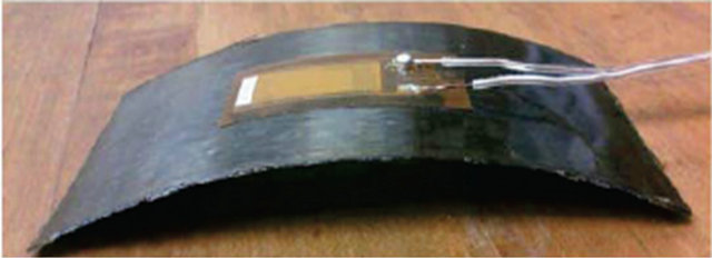
Figure 16. Cylindrical shapes I, II of the rectangular [0/90].
[0/90] laminate, seen in Figure 17. The estimated voltage at snap through was 951.45 V DC, which was close to three times more than the snap through voltage for the rectangular laminate.
After cooling to room temperature and bonding the MFC actuator to the deformed laminates, the piezoelectric actuation experiments are ready to be done. The [0/90] laminates were done first for piezoelectric actuation. As seen in previous chapters for the [0/90] laminate, the snap through from cylindrical shape I should cause the laminate to have actuated displacement along the y-axis in the positive z-direction, this being cylindrical shape II. The rectangular [0/90] laminate is shown in the Figure 18.
As observed in earlier sections, the actuated displacement curvature is predicted by the analytical and numerical models. These predictions are then compared to the experimental results. The rectangular [0/90] laminate comparisons of the numerical and experimental results are reasonably accurate. As expected, the actuated snap through curvature of the rectangular [0/90] laminate is along the y-axis, which is the orthogonal cylindrical shape II. This proves the numerical and analytical models are reasonable prediction models for actuation. The same actuated snap through curvature is expected for the square [0/90] laminate shown in Figures 18 and 19.
Due to the size and flexibility of the laminate, when using the FARO gage CMM to obtain data points the laminate will tend to move. An uncalibrated and unspecified load was required for the FARO gage to capture the deformation date of the flexible laminates. Although a laser profilometer would serve as a better tool for shape and deformation characterization, none were available. The data obtained from the experimental actuation therefore will not be as precise as the FEA ideal models. When comparing the actual experimental result to the FEA model, this error can be seen. Showing similar actuated shapes as the analytical model suggested, the square and rectangular cross-ply laminates behaved as expected. This was done by using the preliminary methods and techniques for modeling the cure process. With the results from those preliminary models, the piezoelectric actuation effect can be more accurately modeled. Modeling the cure process first for preliminary measures of the piezoelectric actuation allowed these methods and techniques to serve as reasonable predictions for the postcure room temperature shapes which is imperative to accurately modeling piezoelectric actuation of unsymmetric laminates.
6. Conclusion
Models were developed to characterize and predict the post-cure shape of the unsymmetric laminates for piezoelectric actuation. The initial model consisted of the CLT where assumptions of the laminate had to be made for the theory to work. Analysis were done with the CLT
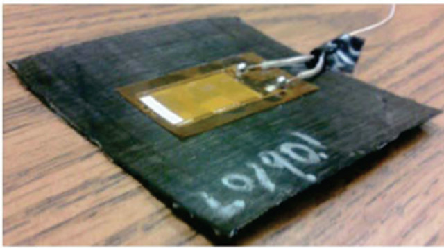
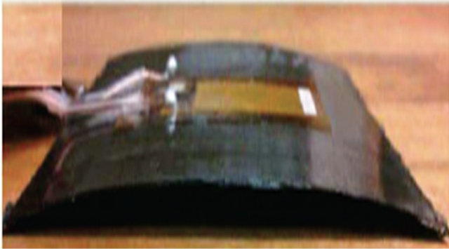
Figure 17. Cylindrical shapes I, II of the square [0/90].
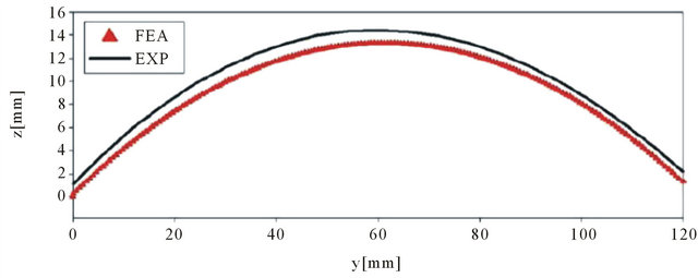
Figure 18. Rectangular [0/90] laminate actuated displacement.
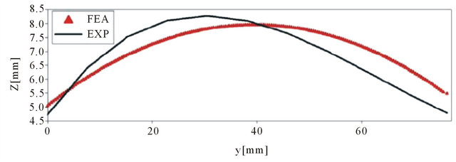
Figure 19. Square [0/90] laminate actuated displacement.
alone and it was observed that the laminates were all deforming to the saddle shape when cooling to room temperature. The CLT predicts that the room temperature shape of all unsymmetric laminates will be the saddle shape. Due to the failure to capture reference strains due to the large out-of-plane deformations as the laminates cool, the CLT had to be extended to account for these strains. This was done by using non-linear strain-displacement equations with the Rayleigh-Ritz technique and minimizing the total potential energy. This gave better predictions of the post-cure shape for the thin laminates. Numerical models were then done to get more accrate predictions of the post-cure room temperature shapes of the thin unsymmetric laminates. Initial pressure was added to the models to simulate the press from the mold. After the initial press was applied, the laminates cooled to room temperature. The numerical models were predicting similar room temperature shapes as the analytical models. After fabricating these laminates, it was observed that the analytical and numerical models were reasonably accurate when predicting the room temperature shapes of the thin laminates. Therefore, the models served as reasonable predictions necessary for piezoelectric actuation. Basic analytical techniques were given for modeling the piezoelectric actuation. Along with experimentation, is was shown that cure process models were able to accurately capture the steps and effects needed later in piezoelectric actuation experimentation.
REFERENCES
- P. Giddings, C. R. Bowen, R. Butler and H. A. Kim, “Characterisation of Actuation Properties of Piezoelectric Bi-Stable Carbon-Bre Laminates,” Composites, Vol. 39, No. 4, 2008, pp. 697-703.
- M. L. Dano and M. W. Hyer, “Snap-Through of Unsymmetric Ber-Reinforced Composite Laminates,” International Journal of Solids and Structures, Vol. 39, 2001, pp. 175-198.
- M. L. Dano and M. W. Hyer, “Thermally-Induced Deformation Behavior of Unsymmetric Laminates,” International Journal of Solids and Structures, Vol. 35, No. 17, 1998, pp. 2101-2120. doi:10.1016/S0020-7683(97)00167-4
- C. R. Bowen, R. Butler, R. Jervis, H. A. Kim and A. L. T. Salo, “Morphing and Shape Control Using Unsymmetrical Composites,” Intelligent Material Systems and Structures, Vol. 22, No. 18, 2007, pp. 89-98.
- M. W. Hyer and A. Jilani, “Predicting the Deformation Characteristics of Rectangular Unsymmetric Laminated Piezoelectric Materials,” Smart Material Structures, Vol. 7, No. 6, 1998, pp. 784-791. doi:10.1088/0964-1726/7/6/006
- M. Schlecht, K. Schulte and M. W. Hyer, “Advanced Calculation of the Room-Temperature Shapes of Thin Unsymmetric Composite Laminates,” Composite Structures, Vol. 32, No. 1, 1995, pp. 627-633. doi:10.1016/0263-8223(95)00080-1
- D. N. Bettes, I. T. Salo, C. R. Bowen and H. A. Kim, “Characterization and Modeling of the Cured Shapes of Arbitrary Layup Bi-Stable Composite Laminates,” Composite Structures, Vol. 92, No. 7, 2010, pp. 1694-1700. doi:10.1016/j.compstruct.2009.12.005
- M. W. Hyer, “Stress Analysis of Ber-Reinforced Composite Materials,” McGraw-Hill Companies, New York, 1998.
- R. M. Jones, “Mechanics of Composite Materials,” Taylor and Francis Group, New York, 1999.
- M. Gigliotti, M. R. Wisnom and K. D. Potter, “Development of Curvature during the Cure of as4/8552 [0/90] Unsymmetric Composite Plates,” Composites Science and Technology, Vol. 63, No. 2, 2003, pp. 187-197. doi:10.1016/S0266-3538(02)00195-1
- F. Mattioni, P. M. Weaver, K. D. Potter and M. I. Friswell, “Analysis of Thermally Induced Multi-Stable Composites,” International Journal of Solids and Structures, Vol. 45, No. 2, 2008, pp. 657-675. doi:10.1016/j.ijsolstr.2007.08.031
- P. Portela, P. Camanho, P. Weaver and I. Bond, “Analysis of Morphing Multi Stable Structures Actuated by Piezoelectric Patches,” Computers and Structures, Vol. 86, No. 3-5, 2008, pp. 347-356. doi:10.1016/j.compstruc.2007.01.032
- C. G. Diaconu, P. M. Weaver and A. F. Arrieta, “Dynamic Analysis of Bi-Stable Composite Plates,” Sound and Vibration, Vol. 322, No. 4-5, 2009, pp. 987-1004. doi:10.1016/j.jsv.2008.11.032
- K. D. Cowley and P. W. R. Beaumont, “The Measurement and Prediction of Residual Stresses in Carbon Ber/ Polymer Composites,” Composite Science and Technology, Vol. 57, No. 11, 1997, pp. 1445-1455. doi:10.1016/S0266-3538(97)00048-1
- L. Ren and A. Parvizi-Majidi, “Cured Shape of Cross-Ply Composite Thin Shells,” Composite Materials, Vol. 37, No. 20, 2003, pp. 1801-1820.
- M. Gigliotti, R. Wisnom and K. D. Potter, “Loss of Bifurcation and Multiple Shapes of Thin [0/90] Unsymmetric Composite Plates Subject to Thermal Stress,” Composite Science and Technology, Vol. 64, No. 1, 2004, pp. 109- 128.
- M. W. Hyer, “Calculations of the Room Temperature Shapes of Unsymmetric Laminates,” Composite Materials, Vol. 15, 1981, pp. 296-309.
- M. R. Wisnom, M. Gigliotti, N. Ersoy, M. Campbell and K. D. Potter, “Mechanisms Generating Residual Stresses and Distortion during Manufacture of Polymer-Matrix Composite Structures,” Composites: Part A, Vol. 37, No. 4, 2006, pp. 522-529. doi:10.1016/j.compositesa.2005.05.019
- PTC, “Mathcad Users Guide,” mathCAD 14.0 Edition, 2007.
- A. J. Vizzini, “Introduction to Composite Materials,” Department of Aerospace Engineering, University of Maryland, College Park, 1990.
- COMSOL Multi-Physics 3.5a, “Structural Mechanics Module Users Guide,” 2008.
- D. J. Leo, “Engineering Analysis of Smart Material Systems,” John Wiley & Sons, Inc., Hoboken, 2007.
- M. R. Schultz, M. W. Hyer, R. B. Williams, W. K. Wilkie and D. J. Inman, “Snap-Through of Unsymmetric Laminates Using Piezocomposite Actuators,” Composite Science and Technology, Vol. 66, No. 14, 2006, pp. 2442- 2448. doi:10.1016/j.compscitech.2006.01.027
NOTES
*Smart Materials Research Laboratory.