Advances in Internet of Things
Vol. 3 No. 2A (2013) , Article ID: 33247 , 8 pages DOI:10.4236/ait.2013.32A002
MAEB: Routing Protocol for IoT Healthcare
1School of Computer and Communication Engineering, University of Science and Technology, Beijing, China
2Department of Electrical Engineering, Korea University, Seoul, Korea
Email: *sunshin@dsys.korea.ac.kr
Copyright © 2013 Haoru Su et al. This is an open access article distributed under the Creative Commons Attribution License, which permits unrestricted use, distribution, and reproduction in any medium, provided the original work is properly cited.
Received March 10, 2013; revised April 15, 2013; accepted April 25, 2013
Keywords: IoT; Healthcare; Routing
ABSTRACT
Healthcare is one of the most promising applications of Internet of Things. This paper describes a prototype for the IoT healthcare systems. We propose the Movement-Aided Energy-Balance (MAEB) routing protocol. The movement and energy information of the neighbor Coordinators are collected and stored in the neighbor discovery procedure. The MAEB forwarding is used to select the most suitable neighbor to forward the data. The simulation results show that the proposed protocol has better performance than the other three routing protocols.
1. Introduction
Healthcare needs a major shift toward more scalable and more affordable solutions. Restructuring healthcare systems toward proactive managing of wellness rather than illness, and focusing on prevention and early detection of disease emerge as the answers to these problems [1]. In the last few years, the Internet of Things in healthcare applications has gained the attention of various researchers in order to cope with the rising healthcare costs. An important task of such a system is to collect physiological parameters like the heartbeat and body temperature. Wireless Body Area Network (WBAN) [2] is one of the most suitable technologies for building unobtrusive, scalable, and robust IoT healthcare systems. A WBAN is composed of structured sensor nodes. These sensors are placed in clothes, directly on the body or under the skin of a person. The sensors are equipped with a wireless interface. Similar to the traditional wireless sensor networks, body sensors collect information about the environment (the human body), that is subsequently correlated for monitoring and/or actuation purposes [1].
Since the wireless sensor nodes are energy constrained, it is necessary to find an energy-efficient routing protocol to deliver the data [3]. The authors of [4] give a survey of energy-efficient routing protocols which can be applied in IoT healthcare systems. However, most of the protocols are designed for the general wireless sensor networks. They did not consider the feature of WBANs. Actually, there are few existing routing protocols for WBANs specially [5].
In this paper, we present architecture for the IoT healthcare systems. It is composed of the WBANs, and a broader telemedicine system. A WBAN consists of multiple sensor nodes, each capable of sampling, processing, and communicating biotic signals. The communication of the WBAN can be supported by IEEE 802.15.6 [2]. All the data packets are delivered to the Access Gateway (AG) by the Coordinators. The AG transmits the information to the medical server through which the medical personnel can get it. In the IoT healthcare systems, the sensor nodes placed on the people move along with them.
We propose the Movement-Aided Energy-Balance (MAEB) routing protocol for the IoT healthcare systems. The first step of MAEB is neighbor discovery. After this step, local Coordinators have the movement and energy information of their reachable Coordinators. And then, according to this information, the Coordinator calculates which neighbor is most suitable to forward the data packet. The MAEB forwarding considers the distance and velocity towards AG, as well as the remaining energy. In the simulation, we compare the performance of MAEB with three other routing protocols: PAOLSR [6], EOLSR [7], and MMPR [8]. We evaluate the performance according to four metrics: latency, energy consumption, packet delivery ratio, and throughput. The simulation results show that the MAEB has the better performance than the other three routing protocols.
The remainder of this paper is organized as follows. In Section 2, we describe the architecture of the IoT healthcare systems. Section 3 introduces the group mobility model and the MAEB routing protocol. Section 4 presents the performance evaluation of our protocol. Finally, Section 5 concludes this paper.
2. Architecture of IoT Healthcare Systems
Recent technological advances in wireless networking, microelectronics integration and miniaturization, sensors, and the Internet allow us to fundamentally modernize and change the way healthcare services are deployed and delivered. The IoT healthcare systems have gained the attention of various researchers. WBANs are one of the most suitable technologies for building unobtrusive, scalable, and robust IoT healthcare systems. They allow an individual to closely monitor changes in user’s vital signs and provide feedback to help maintain an optimal health status.
The architecture of the IoT healthcare systems is illustrated in Figure 1. It is composed of the WBANs and a broader telemedicine system. It services hundreds or thousands of individual users. Each user wears a number of body sensor nodes that are placed on or in the human body, each capable of sampling, processing, and communicating one or more vital signs such as heart rate, blood pressure, oxygen saturation, etc. Typically, these sensors are placed strategically on the human body as tiny patches or hidden in users’ clothes. For example, the heart sensor monitors heart activity. It has a singlechannel bio amplifier for three-lead ECG. This sensor is capable of sending either row ECG signal (signal is filtered) or R-peak events recognized by the on-sensor feature extraction software modules. The activity sensor attached to the user’s belt, an ankle, a knee or the trunk can be used to differentiate user activity states such as sitting, walking, running and lying.
The communication within the WBAN is supported by IEEE 802.15.6 protocol stacks. The beacon-enabled cluster-tree topology is used. For each user, the Coordinator (C), which has more energy and computing ability, organizes the whole network on one human. It collects data from the sensor nodes on or in the human body. In this IoT healthcare system, there is no personal server such as PDA or PC. It can reduce the expenditure of each user. The collected data of Coordinator delivers data to the Access Gateway (AG) through other Coordinators using multiple hop routing. AG may be plugged into either a hospital server or a wired or wireless network appliance. The AG and Coordinators transmit periodic beacon frames to synchronize nodes in the network. The AG also transmits the data to the medical server through Internet. If a user moves out of the communication range (there’s no neighbor user), the Coordinator automatically begin buffering data locally. When the user returns, the route link is reestablished. The Coordinator automatically uploads stored sensor and event data.
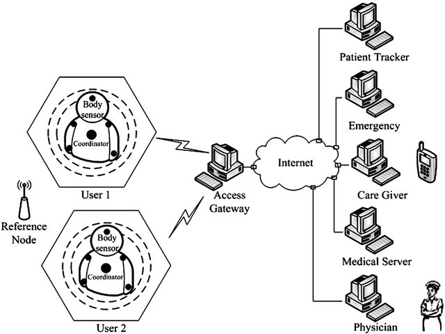
Figure 1. Architecture of the IoT healthcare systems.
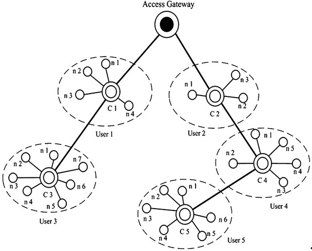
Figure 2. An illustration of the communication structure of the IoT healthcare systems.
Since the users’ location information is also essential in the IoT healthcare system, localization scheme is used. There are some Reference Nodes (RNs) around. They are GPS equipped or preprogramming nodes with their locations. The Coordinators can get their own locations from the signal of RNs and the localization algorithm. The medical provider can analyze the patients’ information and provide medical services. The medical server stores the information of the users and their health information. There is an expert system to diagnose the simple disease. If the situation of the patient is serious, the experts in the hospital can make a diagnosis according to the data of the patient [1]. Through Internet, experts from different places can perform a consultation or collaboration. If the patient needs an ambulance in an emergency, the system can send the instruction to the nearest ambulance on the way. An illustration of the communication structure of the IoT healthcare systems is shown in Figure 2.
3. MAEB Routing Protocol
Routing protocols for the IoT healthcare systems can be divided in intra-body communication and extra-body communication ones. The first controls the information handling between the body sensor nodes and Coordinator. The latter ensures communication from Coordinator to the Access Gateway. In this paper, we just consider the extra-body routing since the intra-body WBAN is star structure. After the body sensors send their data to the Coordinator, there are two kinds of methods to deliver the data from the Coordinator to AG. The first one is single-hop delivery, which means that Coordinator transmits data directly to AG. Another method is multi-hop delivery, which means that other Coordinators forward data to AG. The multi-hop routing method can obtain larger network coverage.
In this section, we will introduce the Movement-Aided Energy-Balance (MAEB) routing protocol. The first step of the MAEB is neighbor discovery procedure which conducts by the Coordinators. After the Coordinators get information of their neighbor Coordinators, they send their packet data to the Access Gateway following a forwarding rule, in which the distance and velocity to the AG and the remaining energy is considered to select the neighbor Coordinator.
3.1. Neighbor Discovery Procedure
Before communication with the AG, the sensor nodes have to complete the association procedure to form the star topology. After that, the Coordinators perform the neighbor discovery procedure. The aim of the neighbor discovery is to establish the neighbor table of Coordinators which get information to decide the route in the following steps. One Coordinator scans the strength of the receiving signals and finds the neighbors in its transmission range. Then one Coordinator establishes a neighbor table to store the information of the neighbors. Figure 3 exhibits an example of neighbor discovery.
The neighbor discovery flow chart is shown in Figure 4. At the beginning of neighbor discovery procedure, the Coordinator establishes a neighbor table to store the information of the neighbor Coordinators. Then it sets a timer to 0. The Coordinator sends a broadcast message to find the neighbors. The Coordinator which receives this message sends a response message containing its information including ID (e.g., address), location, velocity, and remaining energy. We encode location as two fourbyte floating-point quantities, for x and y coordinate values. Before the timer increase to 5, if the Coordinator receives the response from the neighbor Coordinators, it examines it is a duplicate. If its ID is unique, the responding Coordinator will be added to the neighbor table. After the neighbor discovery procedure, the Coordinators
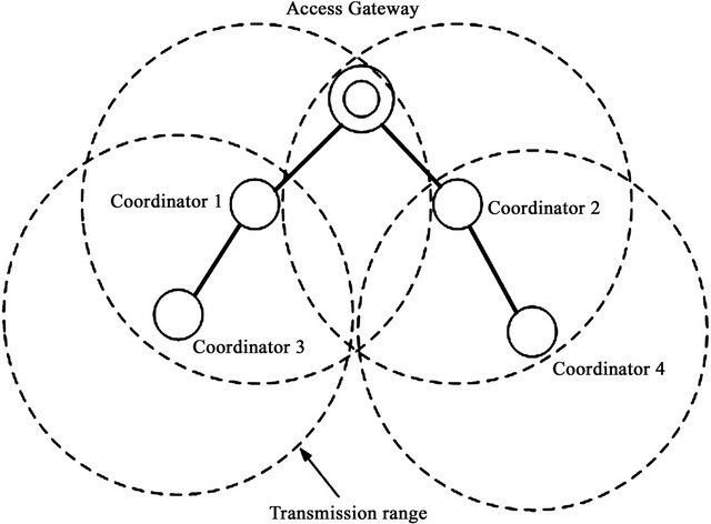
Figure 3. An example of neighbor discovery.

Figure 4. Flow chart of neighbor discovery.
have the information of reachable Coordinators. The neighbor discovery procedure is repeated every period of time to update the neighbor table. The correct choice of update interval depends on the rate of mobility in the network and range of Coordinators’ radios.
3.2. MAEB Forwarding
After the system setting, location information of the AG is stored in every Coordinator of the network. After the procedure of neighbor discovery, the Coordinators have the information of reachable Coordinators, including the movement (location and velocity) and remaining energy. Each Coordinator collects the data packets from its sensor nodes. The destination of these data packets is the AG. When the AG is in the transmission range of the Coordinator, it transmits the data to the AG directly. Otherwise, it sends the data to one of its neighbor Coordinators. The mechanism of the neighbor selection impacts on the packet delay and energy consumption of the whole network.
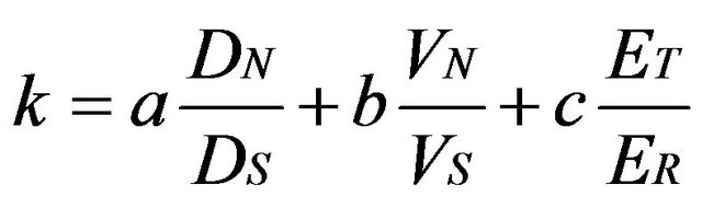
Firstly, the distance from a neighbor Coordinator to AG is considered. Less distance can reduce the average packet delay, as well as the number of hops. Secondly, the relative velocity is concerned. If a neighbor Coordinator is moving towards AG rapidly, it can take the packet close to AG. Thirdly, to balance the energy consumption and prolong the network lifetime, the residual energy of the Coordinator is also took into account. We tend to choose the Coordinator which has more residual energy. A parameter k is defined to indicate which Coordinator neighbor is most suitable to forward the data packet, which can be calculated by
 (1)
(1)
where DN is the distance between the neighbor Coordinator and AG. DS is the distance from Coordinator itself to AG. VN is the relative velocity of the neighbor Coordinator and AG. It is the projection of the velocity vector on the interlink from Coordinator to AG. VS denotes the relative velocity of Coordinator itself and AG. ET is the data packet transmission energy. ER denotes the residual energy of the neighbor Coordinator. There are three weighting parameters a, b, and c, which are between 0 and 1. They can be adjusted according to the application scenario.
The pseudocode of MAEB forwarding is shown in Figure 5. Suppose the address of AG is g.a. The location of AG is g.l. Each C has a neighbor table (N), each of whose entries contain the information of a neighbor Coordinator: address (a), location (l), velocity (v), and remain energy (e). We denote the own address and location of a Coordinator by self.a and self.l. Equation (3) is used to calculate the variable k. k is calculated by l, v, and e. The initial kbest is set to 1. If there is one neighbor Coordinator which has smaller k, kbest is substituted by this value. After one loop, nbest represents the neighbor Coordinator which has the smallest k. This neighbor Coordinator is the most suitable one to forward the data packet. After transmitting data to neighbor Coordinator, next step forwarding begins. This forwarding repeats until the data packet reaches AG.
Figure 6 gives an illustration of MAEB forwarding. In this example, the Coordinator of user 1 has a data packet aim to transmit to the AG. There are four other users in this system, user 2, 3, 4, and 5. The Coordinator of user 4 is not in the transmission range of Coordinator 1 (C1). C1 has three neighbor Coordinators: C2, C3, and C5. The distance from C2 to the AG is shorter than other two Coordinators. Also, based on its velocity and remaining energy, the parameter k of C2 is smaller than C3 and C5. Therefore, C1 forwards the data packet to C2.

Figure 5. Pseudocode of MAEB forwarding.
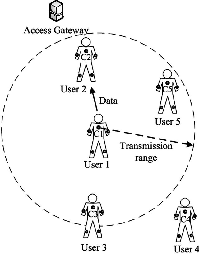
Figure 6. An illustration of MAEB forwarding.
4. Performance Evaluation
To evaluate the performance of the proposed protocol, we did a series of simulations. 100 sensor nodes and 10 Coordinators were deployed in a 10 m × 10 m field. The basic parameters used in the simulation are tabulated in Table 1. The application traffic was a constant distribution with the fixed data rate of 2kbps. All nodes generated their first data frame randomly in one cycle. The data frame had the fixed payload length. The sensor node energy consumptions of the transmission, reception, idle, and sleep were set to 36.5 mW, 41.4 mW, 41.4 mW, and 42 μW, respectively. Each Coordinator starts the simulation by remaining stationary for pause time seconds and moves at a speed distributed uniformly between 0 and 1.5 m/s. The velocity of the sensor node had a differential from its Coordinator, which was a random variable uniformly distributed in the interval [0, 0.5 m/s]. The reason why the speed of mobile node limits is that the body area network not corresponds to the extremely high speed environment. The parameters a, b, and c were set to 1/3. All simulations were run independently and their results averaged fewer than 1000 seeds. The simulation held on for 1000 seconds.
We compared MAEB with PAOLSR [6], EOLSR [7], and MMPR [8] in terms of the latency, energy consumption, packet delivery ratio, and throughput. Firstly, the latency is defined as the average time taken for a data packet from the sensor to the Coordinator. Secondly, the energy consumption denotes the average amount of energy consumed by the sensor nodes. Thirdly, the packet delivery ratio is the ratio between the number of data packets originated by source mobile node and the number of data packets reached by Access Gateway. Fourthly, the throughput is a measure of the average amount of data transmitted from the sensor nodes in a unit period of time (second).
The simulation results of the latency of the routing protocols are shown in Figure 7. With the traffic load increases, the latency increases gradually. When the traffic load is larger than 3pkts/s, the latency of the MAEB is less than that of the other three routing protocols. The MAEB has better performance than the other protocols. The latency of the MMPR is better than that of the EOLSR. The latency of PAOLSR is mostly larger than EOLSR.
The simulation results of the energy consumption are displayed in Figure 8. As the figure shows, the energy consumption also increases gradually with the increase of the traffic load. The energy consumption of the MAEB is considerably reduced compared to the other three routing protocols. The EOLSR consumes less energy than the MMPR. PAOLSR consumes more energy than MMPR. PAOLSR has worse performance than the other three protocols. The differences between the energy consumption of the protocols rise as the traffic load increases.
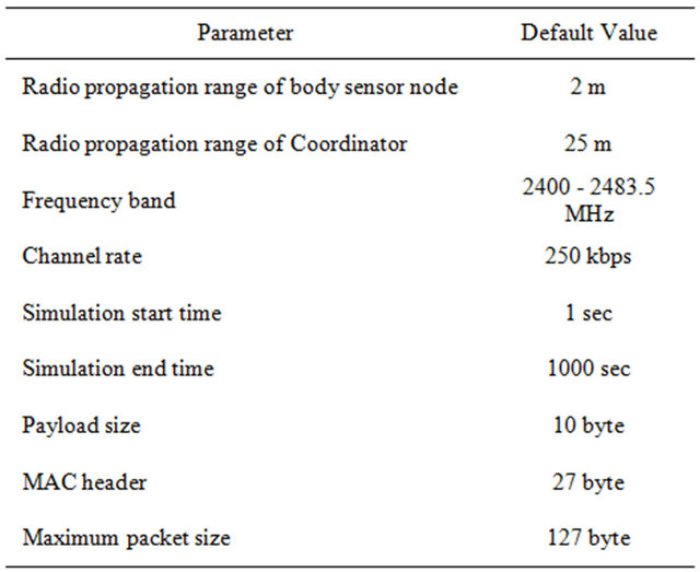
Table 1. Basic simulation parameters.
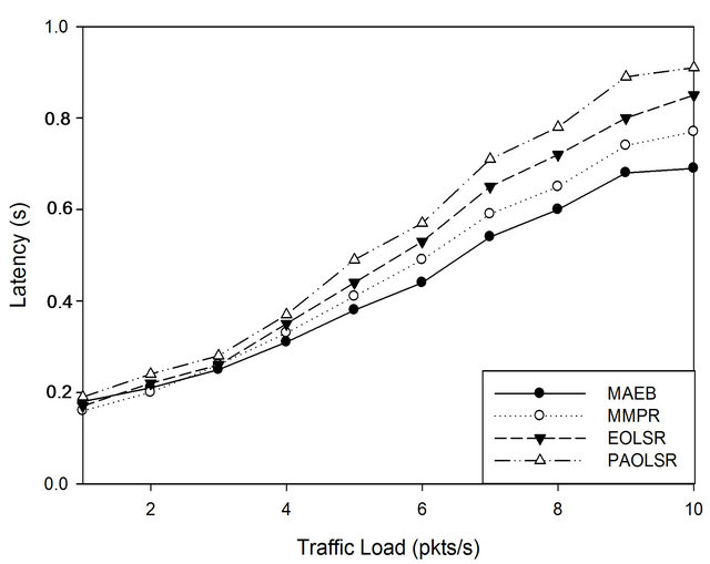
Figure 7. Latency varying with the traffic load.
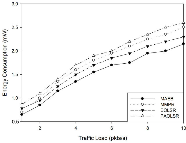
Figure 8. Energy consumption varying with the traffic load.
Figure 9 depicts the simulation results of packet delivery ratio varying with the traffic load. We can see that with the increase of traffic load, the packet delivery ratio decreases gradually. The reason for this is that packets are frequently dropped and the number of backoffs is increased with the higher traffic load. As we know, the requirements of quality of service (QoS) always depend on the application. The packet delivery ratio is thought as one of the measures of the network dependability. In ideal condition, packet delivery ratio equals to 1. In general, the delivery ratio of MAEB is greater than that of the other three routing protocols.
Figure 10 demonstrates the throughput varying with the traffic load. The throughput is an important metric that directly presents the system performance. As the figure shows, the system throughput also increases with the increase of the traffic load. MAEB has better throughput than the other three protocols.
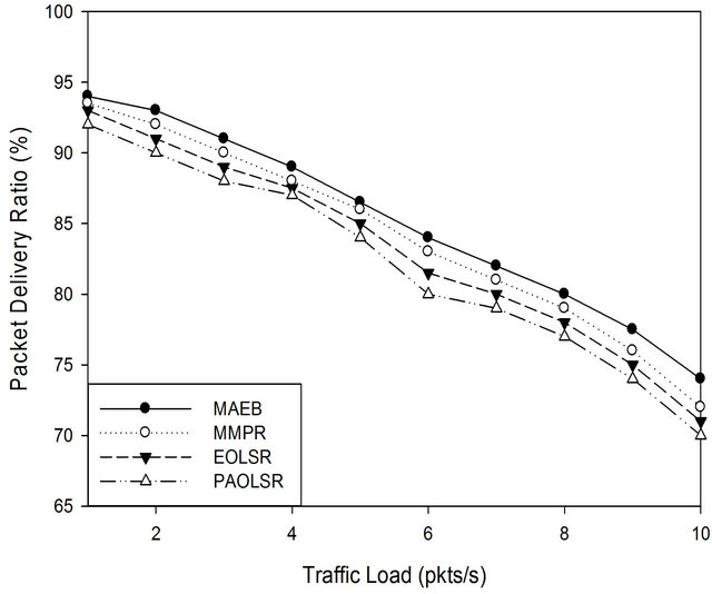
Figure 9. Packet delivery ratio varying with the traffic load.
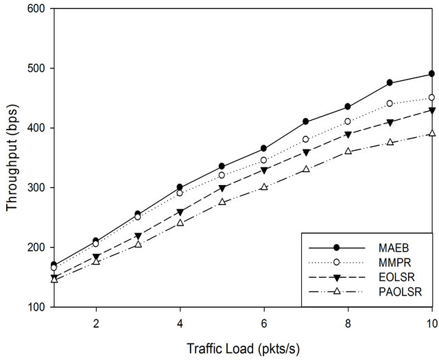
Figure 10. Throughput varying with the traffic load.
5. Conclusion
In this paper we introduce the architecture of an ambulatory IoT healthcare system including Wireless Body Area Networks (WBANs) and a broader telemedicine system. A WBAN consists of multiple sensor nodes. They can collect the vital signs of the user. The information is delivered to the AG through Coordinators. The AG transmits the information to the Internet, where the broad telemedicine system can get it. According to the group mobility character of the WBAN, we use the group mobility model to define body sensor nodes behavior. Using this model, the movement of the body sensor nodes of one user can be represented by their Coordinators. The Coordinators get the movement and energy information of their neighbors in the neighbor discovery procedure. Using the MAEB forwarding, the Coordinator selects the most suitable Coordinator to forward the data. According to the simulation results, MAEB has the better performance than the other three routing protocols.
6. Acknowledgements
This work is jointly supported by National Science and Technology Major Project under Grant No. 2010ZX- 07102-006, National Natural Science Foundation of China under Grant No. 61170117, and Central College Basic Research Foundation under Grant No. 2302013- FRF-TP-13-016A.
REFERENCES
- M. Chen, et al., “Body Area Networks: A Survey,” Mobile Networks and Applications, Vol. 16, No. 2, 2011, pp. 171-193.
- IEEE Standards Association, “IEEE Standard for Local and Metropolitan Area Networks-Part 15.6: Wireless Body Area Networks,” IEEE Standard for Information Technology, IEEE 802.15.6 Standards, 2012, pp. 1-271.
- S. Ullah and K. S. Kwak, “Throughput and Delay Limits of IEEE 802.15.6,” Proceedings of IEEE Wireless Communications and Networking Conference (WCNC), Quintana-Roo, Mexico, 28-31 March 2011, pp. 174-178.
- N. A. Pantazis, S. A. Nikolidakis and D. D. Vergados, “Energy-Efficient Routing Protocols in Wireless Sensor Networks for Health Communication Systems,” Proceedings of the 2nd International Conference on PErvasive Technologies Related to Assistive Environments, Corfu, 9-13 June 2009, pp. 1-8.
- M. A. Razzaque, C. S. Hong, et al., “Data-Centric Multiobjective QoS-Aware Routing Protocol for Body Sensor Networks,” Sensors, Vol. 11, No. 1, 2011, pp. 917-937. doi:10.3390/s110100917
- Z. Guo and B. Malakooti, “Energy Aware Proactive MANET Routing with Prediction on Energy Consumption,” Proceedings of the 2007 International Conference on Wireless Algorithms, Systems and Applications, Chicago, 1-3 August 2007, pp. 287-293. doi:10.1109/WASA.2007.20
- S. Mahfoudh and P. Minet, “EOLSR: An Energy Efficient Routing Protocol in Wireless Ad hoc Sensor Networks,” Journal of Interconnection Networks, Vol. 9, No. 4, 2008, pp. 389-408. doi:10.1142/S0219265908002345
- T. Kunz and R. Alhalimi, “Energy-Efficient Proactive Routing in MANET: Energy Metrics Accuracy,” Ad Hoc Networks, Vol. 11, No. 7, 2010, pp. 755-766. doi:10.1016/j.adhoc.2010.02.004
NOTES
*Corresponding author.