Journal of Flow Control, Measurement & Visualization
Vol. 1 No. 1 (2013) , Article ID: 30567 , 7 pages DOI:10.4236/jfcmv.2013.11002
An Experimental Investigation on the Quasi-Static Flotation Transport of a Glass Substrate Using Vortex Bearing Elements
1Precision and Intelligence Laboratory, Tokyo Institute of Technology, Yokohama, Japan
2Department of Mechano-Micro Engineering, Tokyo Institute of Technology, Yokohama, Japan
Email: *li.x.ad@m.titech.ac.jp
Copyright © 2013 Xin Li et al. This is an open access article distributed under the Creative Commons Attribution License, which permits unrestricted use, distribution, and reproduction in any medium, provided the original work is properly cited.
Received December 17, 2012; revised January 24, 2013; accepted February 10, 2013
Keywords: Flotation Transport; Air Conveyor; Vortex Bearing Element; Vortex Flow; Suction Force
ABSTRACT
In this paper, we build an air conveyor with newly developed vortex bearing elements, and study the flotation precision of the front-end of the substrate in quasi-static flotation transport. We experimentally discuss the three influential factors: air supply pressure, thickness of the substrates and installing direction of the vortex bearing element. We find that during the process of transport the movement of the substrate leads to the variation of flotation height. The amplitude of variation (e.g. flotation precision) is dependent upon the bearing stiffness and the suction force of the vortex bearing elements. Increasing air supply pressure properly can improve the flotation precision, but an excess pressure can cause over-suction due to high negative pressure and result in a poor flotation precision. We also know that the flotation precision of thin and light substrates are easily affected by the suction force of vortex flow because they float with a high flotation height and are more susceptible to deformation. Finally, we investigate four installing directions of the vortex bearing element. Different installing direction can lead to different variation of flotation height.
1. Introduction
When thin and brittle substrates (e.g. liquid crystal glass substrate) are to be transported, air conveyors are usually used [1-9]. Air conveyor is the device that forms an air film between the substrate and the air conveyor, and the substrate floats above the air film. It is commonly used to transport large workpieces. In comparison with roller and belt transport, air flotation causes no scratching or pollution (contact smudge, static electricity pollution) because of no contact between the substrate and the air conveyor. It can also effectively prevent the damage caused by stress concentration. At the same time, since air is clean, easy for maintenance and does not generate heat or magnetic field interference, air conveyor is widely used in the automated production sites for transporting workpieces, including liquid crystal glass substrates and semiconductor wafers [6-9].
Air conveyor is composed of many bearing elements (see Figure 1) [10,11]. Figure 2 shows 3 types of bearing elements: orifice type, porous-material type, vortex type, etc. Among them, the vortex type is a newly developed bearing element [12]. It has a special structure: at the center of the flat bearing surface there is a cylindrical vortex chamber, and in its tangential direction a
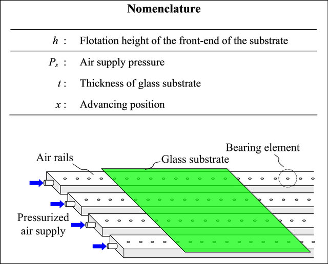
Figure 1. Air conveyor for floating and transporting glass substrate.
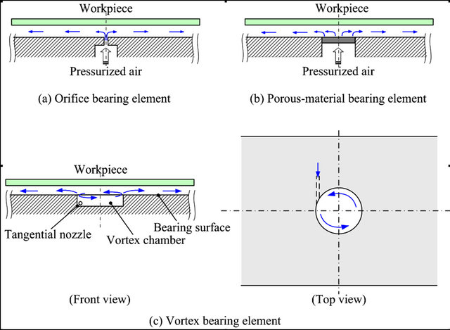
Figure 2. Air bearing elements for air conveyor.
nozzle is inserted. When compressed air is squirted into the vortex chamber through the nozzle, it flows along the wall of the vortex chamber to form a vortex flow. Then airflows into the gap between the substrate and the bearing surface before finally discharge to atmosphere. This structural design makes use of the negative pressure generated by the centrifugal force of the vortex flow. Therefore, this particular bearing element can generate a supporting force on the bearing surface, and at the same time produce a suction force at the center. When the workpiece is floated by a supporting force and a suction force simultaneously, the flotation can be better in bearing stiffness and stability [1].
In our previous research, we analyzed the basic characteristics of a single vortex bearing element, and proved that this type performed better than the traditional orifice-type in terms of bearing stiffness and stress reduction [13]. In this research, we fabricate an air conveyor using vortex bearing elements, and conduct an experimental investigation on the problems that may arise in the actual transporting process to affect the flotation of the substrate. Flotation precision refers to the fluctuation amplitude of flotation height. Take the production process of the liquid crystal glass substrate as an example. Different flotation precision is required depending on the manufacturing processes: coating process and precise inspection requires high flotation precision (±10 - 20 μm); pattern checking requires a flotation precision of ±50 μm, while simple transporting process does not have special requirement on flotation precision.
In this paper, we develop a small-scale air conveyor (Section 2), and investigate the impact of air supply pressure (Section 4.1), weight of the substrate (Section 4.2) and installing direction of the nozzle (Section 4.3) on flotation precision.
2. Experimental Setup
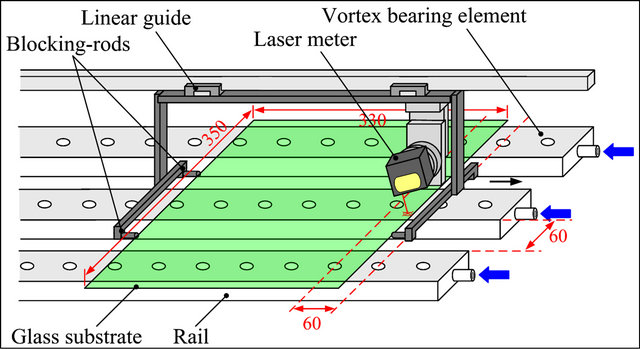
Figure 3 shows the air conveyor we developed. It consists of three 700 mm long rails arranged in an equidistance of 60 mm. The vortex bearing elements on the three air rails are aligned equidistantly (60 mm) on the centerline of the rails. The vortex chamber of the vortex bearing element is 15 mm in diameter and 3 mm in depth, and the nozzle is 0.6 mm in diameter (see Figure 3(b)). The rails are 60 mm in width to have a bearing surface. Given the original intention lies in investigating the variation of glass substrate in a flotation transport, we designed the air conveyor for experiment with increased space between each bearing elements, and we array them in a line such that we can observe obvious variation of flotation height. Although it is an air conveyor with simple design and structure, it can reproduce the problems occurred during the actual transporting process. Therefore, we consider that the observation and discussion derived from the experiments in this paper have universal value.
 (a)
(a)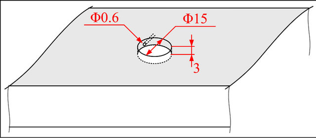 (b)
(b)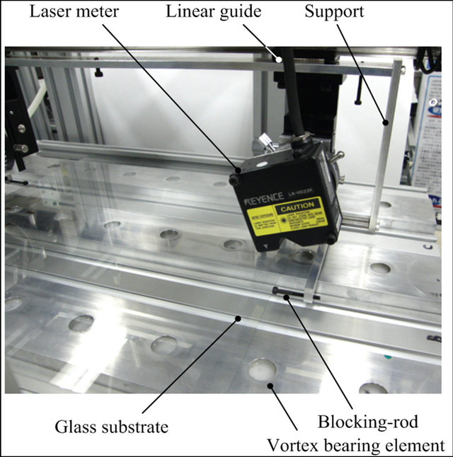 (c)
(c)
Figure 3. Air conveyor and measurement system. (a) Schematic; (b) One vortex bearing element; (c) Photograph.
In the experiments, all glass substrates are 320 mm in length and 350 mm in width, but come in different thickness: 0.4 mm, 0.7 mm and 1.0 mm, respectively. Using glass substrates less than 1 mm in thickness is to create an experimental condition that is similar to real applications. The thickness of glass substrates used in liquid crystal display (LCD) now is generally less than 1 mm. Therefore the weight borne by each bearing element is very small. Blocking-rods are erected on the lateral sides of the substrate (see Figure 3(b)). The blocking-rods and their support are installed on a linear guide, and they can slide when driven by a motor and move the substrate forward on the air conveyor consequently. In this paper, only quasi-static transport is discussed, i.e. the speed of the moving substrate is very low.
To measure the variation of the flotation height when the substrates are being transported, we have installed a laser meter (Keyence, full scale: 6 mm, precision: ± 0.02% of f.s.) above the substrate. The laser meter is of the three-point reflection type, in which the laser beam will be reflected three times: at the upper surface and lower surface of the substrates and the air rail’s surface, respectively. The latter two reflections can be used to calculate the distance from the lower surface of the substrates to the bearing surface of the rail, i.e., the flotation height. The laser meter is connected to the blocking-rods and the support to synchronize its movement with the substrate, and the variation in the flotation height of the substrates at certain point can thus be measured. Furthermore, considering the front-end of the substrate is easiest to be effected during transporting, we installed the laser meter above the front-end of the substrate.
Figure 4 shows the air supply circuit of the air conveyor. After flowing through the regulator, the air is regulated to a given pressure and supplied to the air conveyor. The flow and the pressure of the supplied air are monitored by a flow sensor and a pressure gauge respectively. The three rails of the air conveyor are interconnected, to ensure equal air supply pressure of each rail.
3. An Example of Flotation Transport
In this section, we will show an experimental result to illustrate the variation of flotation height of the substrate during the transporting process. The direction of the nozzles is perpendicular to the movement direction of the substrate; the nozzles are installed on the left side of the vortex chamber (see Figure 5). Along the direction of the transport, the movement of laser meter and that of the substrates are synchronized, in order to track and measure the flotation height of a certain point at the front-end of the substrates. Figure 6 shows the experiment results when the air supply is 20 kPa, and the thickness of the substrate is 0.7 mm. The substrate’s flotation height is about 200 μm, and it fluctuates when the substrate is being transported forward. For convenience, we denote some key positions as A, B, C and A’, respectively in the figure.
When the front-end of the substrate is located between the two bearing elements (at position A), the center of all the bearing elements which support the substrate basically coincides with the center of mass of the substrate. Thus the substrate is at a relatively high flotation position. Approaching the next bearing element (from A to B), the center of mass of the substrate moves forward, and hence deviates from the center of the bearing elements. This deviation has caused a slight downward inclination of the front-end of the substrate. Moving further ahead, the front-end gradually enters into the vortex chamber of the next vortex bearing element (from B to C). Because of the support from the air of the new vortex bearing element, the front-end of the substrate stops the downward inclination, and is kept at a certain flotation height. When the substrate reaches position C, the flotation height of the front-end decreases sharply. This is due to the fact that the vortex chamber is completely covered by the substrate, and as a result the vortex flow inside the chamber is separated from the external atmosphere. Therefore, the vortex flow forms a negative pressure distribution in the chamber [14,15]. The negative pressure distribution generates a suction force acting on the front-end of the substrate, consequently causing an abrupt decrease of the flotation height. Then the substrate passes through the vortex chamber (form C to A’), and a gap is formed between the substrate and the bearing surface of the rails. The air flows into the gap, and because of the viscous upward supporting force generated by the positive pressure distribution gradually lifts up the front-end of the frictiona positive pressure distribution is formed. An substrate. After reaching A’, the substrate completes a transport cycle, and moves back to the same flotation
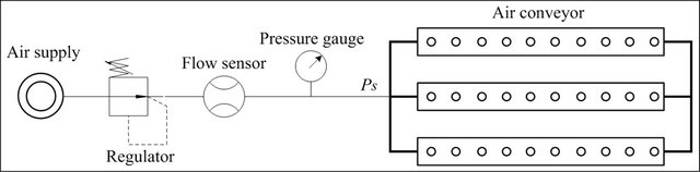
Figure 4. Supply circuit of pressurized air supply.
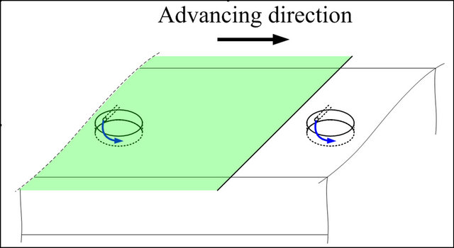
Figure 5. Installing direction of the vortex bearing elements.
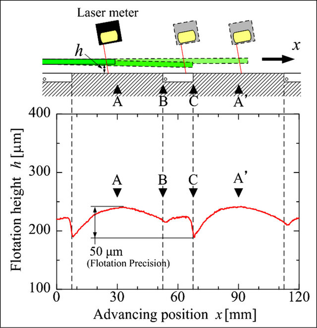
Figure 6. The change in flotation height during the transporting process (the air supply pressure is 20 kPa(g), the substrate is 0.7 mm thick).
height as at position A. We can see that in a transport cycle, the flotation height of the front-end of the substrate fluctuates (i.e. flotation precision) by about 50 μm.
4. Influential Factors on Flotation Precision
In this section, we study the factors influencing flotation precision, including air supply pressure, weight of the substrate and the direction of the nozzle.
4.1. Influence of the Air Supply Pressure
Experimental conditions in Figure 7 (thickness of the substrates and the direction of the nozzles) are the same as those in Section 3. Air supply pressures are 40, 30, 20 and 10 kPa(g) respectively. As air supply pressure increases, the air flow, viscous effect on the bearing surface, positive pressure distribution as well as supporting force increase. Hence we have a slight increase of the flotation height of the substrate. When advancing from A to B, regardless of the air supply pressure, the front-end of the substrate inclines downward as the center of mass shifts. However, we notice that when air supply pressure increases, the amount of downward inclination decreases. It is because increasing air supply pressure can also increase the bearing stiffness of every bearing element. At
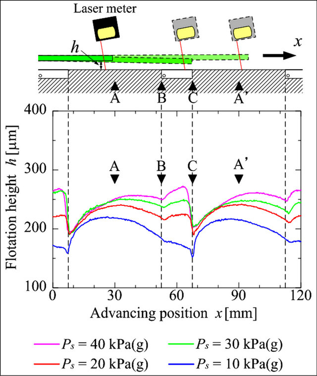
Figure 7. The influence of air supply pressure on flotation precision (the thickness of substrate is 0.7 mm).
a higher bearing stiffness, the inclination of the substrates is less likely to occur. Moving from B to C, the front-end of the substrate enters into the next vortex chamber, and is supported by the air from the nozzles. Therefore, the substrate’s inclination tendency is altered. We can see that if the air supply pressure is too low (e.g. Ps = 10 kPa(g)), the air flow is insufficient to reverse the inclination of the substrate. When the substrate reaches C and covers the vortex chamber completely, a negative pressure distribution is formed inside the chamber, and as a consequence, a suction force is generated and acts on the front-end of the substrate. With increased air supply pressure, negative pressure distribution and the suction force become bigger. Therefore, the variation of flotation height at position C increases more markedly. On the contrary, at a lower air supply pressure, the flotation height only decreases slightly. When the front-end of the substrate is transported out of the vortex chamber, the flotation height increases gradually and reaches the highest value at position A’. Finally, we compare the change of the flotation height under three different air supply pressures: 10 kPa(g), 70 μm; 20 kPa(g), 50 μm; 30 kPa(g), 46 μm; 40 kPa(g), 71 μm. Thus a relatively higher air supply pressure can increase the bearing stiffness and thus improve the flotation precision. But an excess pressure can cause over-suction due to high negative pressure, and lead to a poor flotation precision.
4.2. Influence of the Substrate Weight
In this section, we use 3 kinds of substrates that are 0.4 mm, 0.7 mm and 1.0 mm in thickness respectively. Figure 8 shows the experiment results under the air supply
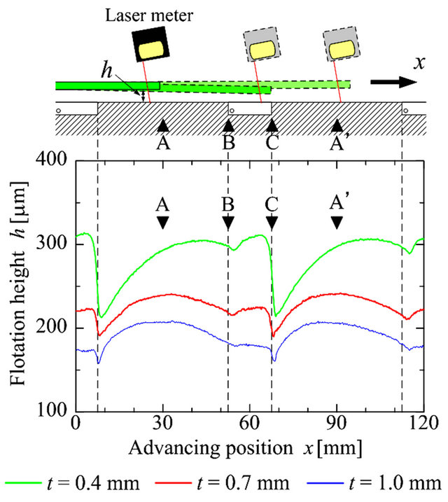
Figure 8. The influence of substrate weight on flotation precision (the air supply pressure is 20 kPa(g)).
pressure of 20 kPa(g). Thinner substrates are lighter, and have larger flotation height, which would increase the suction force caused by negative pressure. We can know from previous research that, within the range of hundreds of micro-meters, the suction force generated by the vortex flow will increase as the distance from it to the transported object increases [14]. From result of the 0.4 mm thick substrate, we find that the increase of suction force has a marked impact on the flotation precision. When the substrate reaches position C and covers the vortex chamber completely, the substrate begins to incline downward significantly. When substrates that are 0.7 mm and 1.0 mm in thickness are used, the tendency of downward inclination at position C is weakened. Moreover, from the perspective of material mechanics, thin substrates are less rigid, and relatively pliable. Therefore, the front-end of the substrate will bend when being attracted. This is another reason for the variation of flotation height for the case of thin substrates. Finally we compare the flotation precision of the substrates of three different thicknesses: the variation of flotation height for 0.4 mm thick substrate, almost 100 μm; 0.7 mm thick substrate, 50 μm; 1.0 mm substrate, less 50 μm.
Results in Figure 8 suggest that when transporting lighter and thinner substrates, lowering air supply pressure might be able to improve the flotation precision. Figure 9 shows the results when air supply pressure is 10 kPa(g). For 0.4 mm thick substrate, the trend of downward inclination at position C is inhibited; its fluctuation of flotation height decreases to 82 μm, an almost 20 μm improvement compared with the result under 20 kPa(g). However, as mentioned in Section 4.1, decreased air supply pressure leads to smaller flotation stiffness. For this reason, for 0.7 mm and 1.0 mm thick substrates, the flo-
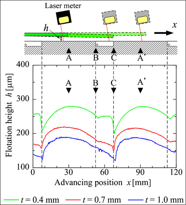
Figure 9. The influence of substrate weight on flotation precision (the air supply pressure is 10 kPa(g)).
tation precision deteriorates.
4.3. Installing Direction of the Nozzles
As had been introduced in our previous research, the vortex bearing element is different from the traditional bearing elements (e.g. orifice-type and porous-material type): the air is squirted out of the nozzles in the direction that is in parallel with the substrate, rather than blowing air head-on to the substrate [13]. Therefore the install direction of the nozzles relative to the movement of the substrates might have an effect on the flotation. To investigate the influence, we change the installing direction of the nozzles. Figure 10 shows four installing directions, denoted as types I, II, III and IV respectively. In type I, nozzles are perpendicular to the movement of the substrates and at the left side of the vortex chamber. All the nozzles used in the above experiments are of this type. Along the rotary direction of the vortex flow, the nozzles advance ahead for multiple of a quarter of the circumference for types II, III and IV.
Figure 11 shows the results when the air supply pressure is 20 kPa(g) with using 0.7 mm thick substrate. Different installing direction of the nozzles can lead to different tendency. From A to B, the flotation height of type III and IV was lower, with a greater tendency of downward inclination. After entering the vortex chamber, types I, III and IV all have their heights increased, with type IV in sharpest increase. It may due to the fact that type IV has nozzles facing towards the substrates, and blows the maximum amount of air into the gap between the substrate and the bearing surface formed over the rails. In comparison, type II has its nozzles backing on to the substrate, which makes the air more difficult to enter
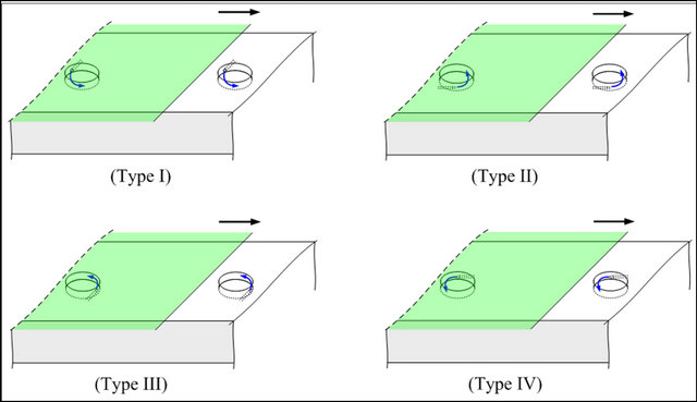
Figure 10. Four installing directions of the vortex bearing element.
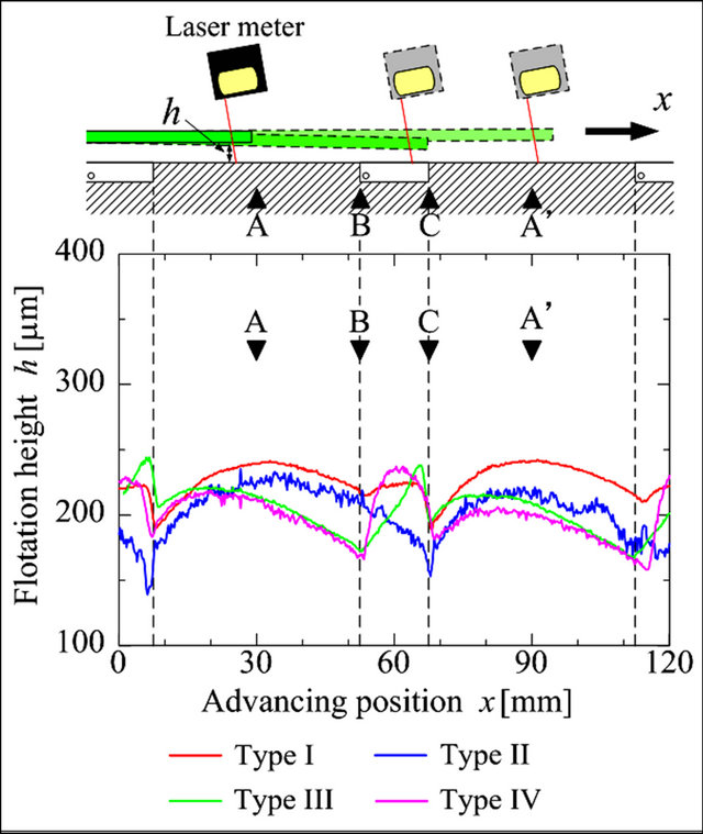
Figure 11. The influence of installing directions of the vortex bearing element on the flotation precision (the air supply pressure is 10 kPa(g), the substrate is 0.7 mm thick).
the gap below the substrate. Therefore, from B to C, the downward inclination of flotation height persists. When the substrate reaches position C, the flotation height of all four types decreases abruptly. As we have illustrated before, this is because the vortex chamber is completely covered by the substrate, and a negative pressure distribution generated by the vortex has a suction force on the substrate. For types I, III and IV, the amount of decrease is similar, while in type II, the reduction is smaller. This is due to the fact that when the front-end of the substrate reaches position C, type II has a flotation height lower than that of the other three types. Our previous research has shown that when flotation height decreases, negative pressure distribution and suction force become weaker [14]. After the substrate has passed position C, the air flowed into the gap between the substrate and the bearing surface, and the flotation height of all four types shows the tendency of returning.
5. Conclusions
In this paper, we have an air conveyor built with newly developed vortex bearing elements, and study the flotation precision of the substrate in quasi-static transport. We experimentally discuss the three influential factors: air supply pressure, thickness of the substrates and installing direction of the vortex bearing element. The results are the following:
1) During the process of transport, the movement of the substrate can lead to the variation of flotation height. The amplitude of variation is dependent upon the bearing stiffness and the suction force of the vortex bearing elements.
2) With higher air supply pressure, the bearing stiffness of the substrates will increase, but at the same time, the suction force generated by the vortex also increases. Therefore, it is not favorable to set the air supply pressure very high; we need to consider both of the two factors before setting an appropriate air supply pressure.
3) Thin and light substrates will have a high floating position. But they are more susceptible to deformation and hence to the suction force generated by the vortex flow. Under this circumstance, we can lower the air supply pressure to decrease the suction force and improve the flotation precision.
4) Vortex bearing element differs from traditional elements in the installing direction of the nozzles. Vortex bearing element has its nozzles arranged in parallel with the substrate, rather than blowing air head-on to the substrate. Therefore the flow direction of the air relative to the movement of the substrates has an impact on the flotation precision. Different installing direction can lead to different variation of flotation height.
6. Future Work
To better understand and utilize the air conveyor composed of vortex bearing elements, our future work will focus on the following topics:
1) The impact of the speed of transporting In this paper, we have assumed the quasi-static transport. However in practical application, the maximal speed can reach 2 m/s. The impact of the speed of transporting on flotation precision will be investigated with emphasis.
2) The optimizing design of the vortex bearing element The vortex bearing elements used in the present study are designed based on experience. Through the present experiment, we have found that it is of significance to study the optimizing design of the vortex bearing element in order to improve flotation precision.
3) Theoretical modeling on flotation of the substrate At present, our research relies mainly on experimentation. In the future, we will develop theoretical models for the flotation of the substrates to investigate the impact of bearing stiffness, suction force and the elastic deformation of the substrates.
REFERENCES
- D. Devitt, “The Physics of Glass Flotation,” Semiconductor International Japan, Vol. 5, 2009, pp. 20-25.
- J. A. Paivanas and J. K. Hassan, “Air Film System for Handling Semiconductor Wafer,” IBM Journal of Research Development, Vol. 23, No. 4, 1979, pp. 361-375. doi:10.1147/rd.234.0361
- Y. L. Srinivas, K. N. Seetharamu and M. A. Parameswaran, “Investigation of Air Film Conveyor Pressurized through Multiple Holes,” Finite Elements in Analysis and Design, Vol. 6, No. 3, 1990, pp. 235-243. doi:10.1016/0168-874X(90)90029-E
- H. G. Lee and D. G. Lee, “Design of a Large LCD Panel Handling Air Conveyor with Minimum Air Consumption,” Mechanism and Machine Theory, Vol. 41, No. 7, 2006, pp. 790-806. doi:10.1016/j.mechmachtheory.2005.10.009
- K. Amano, S. Yoshimoto and M. Miyatake, “Basic Investigation of Noncontact Transportation System for Large TFT-LCD Glass Sheet Used in CCD Inspection Section,” Precision Engineering, Vol. 35, No. 1, 2011, pp. 58-64. doi:10.1016/j.precisioneng.2010.08.010
- CoreFlow. http://www.coreflow.com/
- New Way Air Bearings. http://www.newwayairbearings. com/
- Daiichi Institution Industry. http://www.daiichi-shisetsu. co.jp
- Oiles Corporation. http://www.oiles.co.jp/
- B. C. Majumdar, “Externally Pressurized Gas Bearings: A Review,” Wear, Vol. 62, No. 2, 1980, pp. 299-314. doi:10.1016/0043-1648(80)90175-1
- W. A. Gross, “Gas Bearings: A Survey,” Wear, Vol. 6, No. 6, 1963, pp. 423-443. doi:10.1016/0043-1648(63)90279-5
- H. Ozawa, K. Kakuda and T. Yasuda, “Noncontact Air Conveyor,” Japan Patent No. P2010-92724, 2010. (in Japanese)
- X. Li, M. Horie and T. Kagawa, “Study on the Basic Characteristics of a Vortex Bearing Element,” International Journal of Advanced Manufacturing Technology, Vol. 64, No. 1-4, 2013, pp. 1-12. doi:10.1007/s00170-012-4372-0
- X. Li, K. Kawashima and T. Kagawa, “Analysis on Vortex Levitation,” Experimental Thermal and Fluid Science, Vol. 32, No. 8, 2008, pp. 1448-1454. doi:10.1016/j.expthermflusci.2008.03.010
- I. Kim, X. Li, C. Youn, K. Kawashima and T. Kagawa, “Research on a Non-Contact Handling System Using Swirling Flow (3rd Report: Effect of Positional Relationship between a Vortex Cup and a Transporting Object),” Japan Fluid Power System Society, Vol. 42, No. 4, 2011, pp. 67-73.
NOTES
*Corresponding author.