Open Journal of Earthquake Research
Vol.2 No.3(2013), Article ID:35777,13 pages DOI:10.4236/ojer.2013.23006
Shockproof Experimental Study of Automated Stocker System in the High-Tech Factory
1Innolux Corporation, Chinese Taipei
2National Center for Research on Earthquake Engineering, Chinese Taipei
Email: *Vivien.Tsai@innolux.com
Copyright © 2013 Jyh-Chau Wang et al. This is an open access article distributed under the Creative Commons Attribution License, which permits unrestricted use, distribution, and reproduction in any medium, provided the original work is properly cited.
Received June 7, 2013; revised July 12, 2013; accepted August 6, 2013
Keywords: High-Tech Facilities; Automation Stocker System; Shake Table Test; Viscous Dampers
ABSTRACT
This study, with the shake table experiments in the National Earthquake Engineering Research Center, investigated the seismic behavior of automation stocker system. The automation stocker system provided a fast and effective method for stocking products in the high-tech facilities. Firstly, the original machine tests for testing common stocker system were to investigate the seismic capacity and failing modes. Secondly, the team completed 2 kinds of reinforcement tests to investigate the seismic behavior: 1) the installation of bracing to improve overall stiffness; 2) the installation of the viscous dampers to improve the overall damping ratio. In comparing the results and performance of the three experiments, we learned from the results of the top-layer acceleration: the installation of bracing had the largest acceleration value, the original machine the second acceleration value and the damper the lowest acceleration value; the best effect was the installation of the damper. The result of the comparison of the top floor displacement meter showed that the highest data was the original machine; the second data was with the damper, the lowest data was the installation of the bracing. Based on the preliminary assessment on the best seismic retrofit ways of the storage system, we further examined the feasibility and applicability of automatic storage seismic retrofit in the high-tech factory.
1. Introduction
1.1. Background and Motivation of the Study
The Science Park is the country’s economic arteries (Hsiao, Pei-Fang, 2005) [1]. Because Taiwan is located on circum-Pacific seismic belt, one of the highly frequent seismic areas, the amount of investment in high-tech industrial equipments is usually really extremely; a single process equipment may cost over 3 million US dollars. Therefore, in the high-tech industries, from the stand points on operating and cost in business, equipment for seismic assessment should be given high priority [2]. To prevent potential serious damage caused by earthquake, the main process equipment and production lines are required to improve seismic design in the structure of the system. In order to ensure that Taiwan’s high-tech Industry obtain satisfactory shockproof process equipment in dealing with earthquakes, the plants are requested to research and develop sustainable technology [3]. Therefore, the various high-tech industries are actively involved in issues of shockproof.
1.2. Literature Review
Different from traditional architecture, the special demand for the constructional structure of the high-tech factories not only requires stringent structural seismic safety, but also provides substantial prevention from micro vibration harm in the clean room of manufacturing environment [4].
With the high-tech industry continuing to rise, the increasing demands in manufacturing process are also facing new challenges in display industry. The most obvious changes are the increasing size of the glass panel, a single equipment size increasingly became larger and its function more complex. The facts in various equipment manufacturing process, complex construction and enormous numbers can cause impact on the baseline assessments of the equipment seismic demand (Chen, Chang-Liang, 2008) [5].
The Automated Material Handling System, AMHS, is the central system to reach manufacture process automation. The clean room stocker is one of important components in display factory. The automation Stocker System was shown in Figure 1, Lin, Kun-Bin (2007) [6].
The system is able to use stocker space efficiently by using computer online system to realize automated control manufacture, and continue to check the expired or overdue inventorial products. It can prevent poor inventory and improve management efficiency, as well, shorten producing time and reduce the operating cost. The AMHS application has become the main-stream in display factory.
Due to the nature of aluminum extrusion materials which is light weight, high stiffness, and simplicity to assemble, the aluminum extrusion materials have been generally used on cover and the internal structure for the AMHS in the clean room. This experiment aims to explore what the stocker’s situation of the overall structure is, using aluminum extrusion materials, when earthquakes occur.
Following generations of evolution, the size of glass panel and the storage system are relatively enlarged. In the large stocker system, a full load of Cassettes weights about 600 kg; its length and width are 4 m, and height up to 7 m.
When an earthquake occurs, due to the overall cassette mass ratio is more than the shed bit, the whole stocker with low stiffness tends to have shaken violently which causes fraction of the glass panel as cassette edges slide off and collide. Another issue is that the automated stocker system is high precise equipment. If the shed bit is excessively deformed, it will affect the accuracy of the operation of the mechanical arm. When the situation is critical, the system is required to stop and be examined. When the duration is extended, the problems in production line are consequently followed.
The stocker overall structure is low stiffness; therefore, it tends to shake violently. Consequently, seismic force convey upwards to the top of the stocker structure and
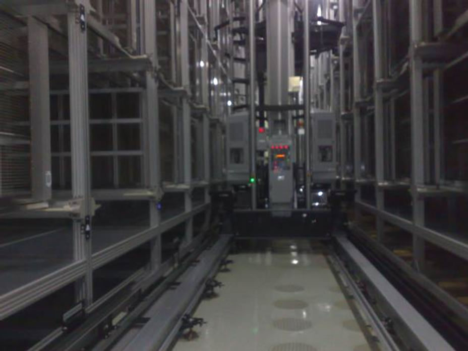
Figure 1. Automation stocker system.
amplifies its effects. This study will examine and test the reinforcement measures: method 1, the team installed the bracing to improve the overall stiffness of the Stocker which will inhibit displacement issue, but it can be expected that acceleration will increase and enlarge. Method 2, the team installed a damper, the function of the damper is to increase the damping (or impedance) of the structure, and to reduce the vibration of external forces by earthquake or wind.
The main principle of the damper is to use the characteristics of the material itself to achieve the effect of energy conversion. The dampers in the market include fluid viscous damper (FVD), viscoelastic dampers (VE Damper) and Viscous Elastic Material (VEM), and the characteristics and speed of the force have proportional relationship. Usually, it will not excessively increase the overall stiffness of the structure. Therefore, the low stiffness Stocker sample with installation of the damper is expected to reduce the absolute acceleration and displacement of the stocker at the same time.
1.3. Study Aim
In this study, the AMHS took the high-tech factory as the research background; the main purposes are to explore the original machine tests because there is no reliable information for the equipment for high-tech industry. We need to understand both how to improve and reinforce the seismic strategies and technical content, in order to modify the failing mechanism in equipment during earthquake. To strengthen seismic retrofit to the failing mechanism, the study tested common stocker system to investigate the seismic capacity and failing modes. The stocker was designed by original manufacturer and was used in the high-tech factory.
The team completed 2 kinds of reinforcement tests to investigate the seismic behavior: 1) the installation of bracing to improve the overall stiffness; 2) the installation of the viscous dampers to improve the overall damping ratio. This pilot study used the stocker with the shake table experiments in the National Earthquake Engineering Research Center. It is expected to enhance the seismic capacity of the original designed stocker. The experimental results can be discussed to give concrete proposals for the best reinforcement and to upgrade the seismic capacity.
2. The Original Machine Tests of the Stocker System
This pilot study used the D6000 type stocker with the shake table experiments in the National Earthquake Engineering Research Center. The original machine tests for testing single stocker system, D6000 type, were to investigate the seismic capacity and failing modes. The D6000 type stocker was designed and manufactured in Japan and was used in the high-tech factories. The stocker for storing is an important equipment for storing a large number of both semi-finished and finished products.
2.1. Micro-Vibration Measurement for the High-Tech Factory
In order to accurately simulate the effect upon Stocker by seismic forces at its location, the National Center for Research Earthquake Engineering was commissioned to conduct the micro vibration measurement. The micro vibration measurement sensors were Model VSE15D speed type micro vibration meter, made by Tokyo SOKUSHIN Co., LTD. The micro vibration meter has both the horizontal and vertical radial velocity measurement; the duration of measurement was 250 seconds, with a sampling frequency of 200 Hz. The layout of micro-vibration sensors in the high-tech factory was shown in Figure 2. The sensors installed on each floor, e.g. placed at escape ladders, and are distant from the process equipments to avoid the influence of vibration by the process equipments themselves. The micro-vibration sensors in the stocker installed at top-layer. It helps to understand the factory structure and floor frequency by the measurement. Then, the team used the measurement result to translate and meet the panel site’s potential designed response spectra.
The result of micro-vibration measurement for this high-tech factory, showed that the structure’s frequency of X direction is 1.22 Hz; the structure’s Y direction is 1.04 Hz (as Figure 2). For the stocker system with cassettes, the natural frequency of X direction is 4.53 Hz; the natural frequency of Y direction is 4.9 Hz. For the high-tech factory, the stick model can be built based on the micro-vibration measurement results. The team chose the closest stations to the panel site that is the 0304 seismic wave, Chiahsien earthquake in Taiwan, from CHY099 Shanhua elementary measure station.
Figure 3 shows the inputted signals following the research of all the shake table tests, respectively, the X is shock waves GX (NS), Y is shock waves GY (EW), and Z is axial shock waves GZ (V). The time history showed at Figure 3. For simulation of the ground surface acceleration, the team established the response spectrum of artificial acceleration, the tri-axial duration history shown in Figure 4. The response spectrum met the Taiwanese official code Seismic Design Specifications and Commentary of Buildings. Furthermore, the team simulated the seismic waves of actual floor to investigate the seismic behavior of equipment in the high-tech factory.

Figure 2. The locations of accelerometer in the factory and stocker are shown by the dots.

Figure 3. The signal, the X shock waves GX (NS), Y shock waves GY (EW), and Z axial shock waves GZ (V) were inputted respectively for the shake table test.

Figure 4. The tri-axial duration history: GX (NS), GY (EW), GZ (V). The 0304 seismic wave, Chiahsien Earthquake in Taiwan, from CHY099 the Shanhua Elementary Measure stations. The response spectrum met the Taiwan Official Code Building Seismic Design Specifications and Commentary.
2.2. Experimental Equipment and Establishing
The shake table tests were held in the National Earthquake Engineering Research Center; the specification of the shake table was 5.1 m × 5.1 m. The sample size of stocker-D6000 type was 4000 × 3050 × 7680 mm, and the total weight was 5650 kg. The stocker includes an empty scaffold with eight cassettes (Cassette, referred as CST), and a single CST weights 600 kg. The configuration of overall experimental stocker structure was shown in Figure 5. The fixed form of the stocker met the actual situation which was 12 feet locked solid on the base; and the base was fixed by expansion bolts to the concrete frame.
The two forms of MC-Nylon stopper were installed in Cassette shown in Figure 6. The right side of MC-Nylon CST refers to RCST. That was the original condition of the MC-Nylon stopper in the stocker. The left side of MC nylon stopper CST refers to LCST. The LCTS was mounted metal stopper and using rubber cushioned material. The purpose of the MC-Nylon stopper installation was to limit Cassette moving range when earthquakes occur.
The accelerometer and displacement meters of the installed position was shown in Figure 7. Both sensors are installed on the diagonal corners of the top layer, the first layer and the bottom layer of the stocker. The accelerometers measured the three axes—X, Y, and Z axes. The displacement meter measured for the X and Y axes.
To explore the CST seismic scenario, the three-axial accelerometer was equipped at the top layer of the two CST. The two CST, right side and left side, were at the top layer of stocker. For observing and simulating the glass sliding condition inside the CST during earthquakes, the team selected PVC board. In addiction, in order to avoid the damage of the shake table or personal injuries as the experiment of the shack table may result in glass breakage or falling. Also, the friction coefficient of PVC board is similar to glass. The result of the experimental test showed the friction coefficient of the glass with the support material is approximately 0.51; the friction coefficient of the PVC board with the support material is about 0.45.
2.3. Result
2.3.1. The Damage Situation of the Stocker
The first phase of the experimental results showed that when PA was 200 gal, the torsion and shaking of the storage space occurred slightly. The CST on the top layer also found little displacement, but it did not cause stopper collision. when PA were 300 gal and 400 gal, the storage spaces of stocker vibrated significantly; it caused large displacement and collision between stopper and CST on the top layer of CST. Few parts of the PVC boards slid away.
The second phase: the aim for the experiment was to understand the ultimate strength of stocker. When PA was 500 gal, rocking and shaking in the storage spaces of the stock occurred violently. The top-layer CST are displaced and hit the stopper and darted out of the PVC boards, and the screws were loosened on the first layer of left cassette’s flange with trellis joint, shown in Figure 8.
When PA was 600 gal, rocking and shaking violently in the storage spaces of the stock occurred. The RCST and LCST displaced rearward and exceeded beyond the limitation of the MC-Nylon. The cassette was stuck on the edge of the MC-Nylon stopper and could not to move; a large number of PVC board had slid; therefore, the experiment ended. Finally, the team inspected the overall stocker structure and found that the screws loosened on the first layer of left cassette’s flange with trellis joint, the condition was the same with experiment in PA for 500 gal. Further, due to severe squeeze, the metal stopper with rubber cushioned material was fractured at the join.
2.3.2. Analyzed the Frequency-Measuring with White Noise
Following the experiment of 400 gal and 600 gal, frequency-measuring with White Noise was analyzed; it was PA for 50 gal, and 1 - 50 Hz. The purpose of frequency-measuring with White Noise was to observe storage spaces after 400 gal and the 600 gal limit tests of
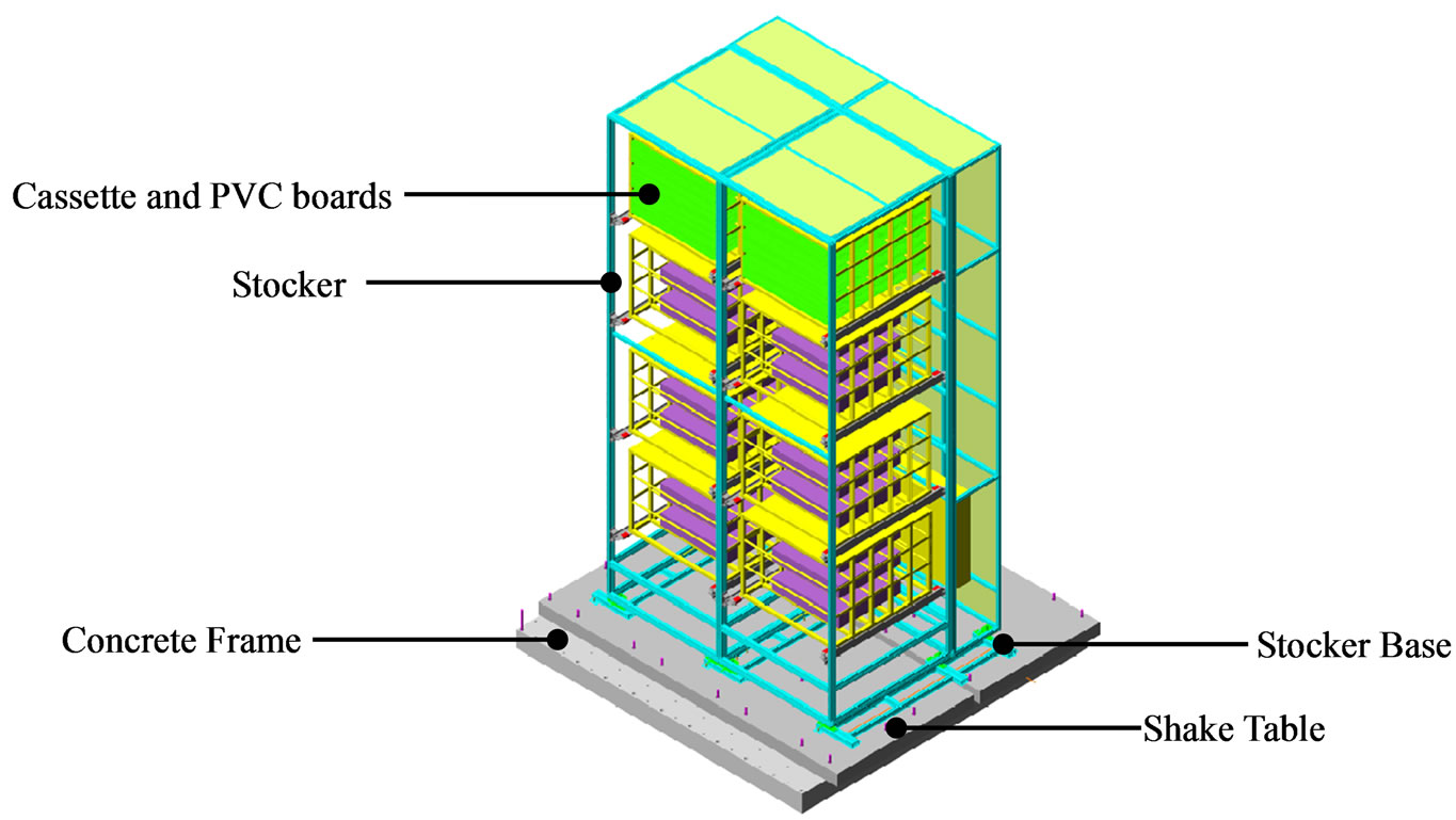
Figure 5. The configuration of overall experimental stocker structure.
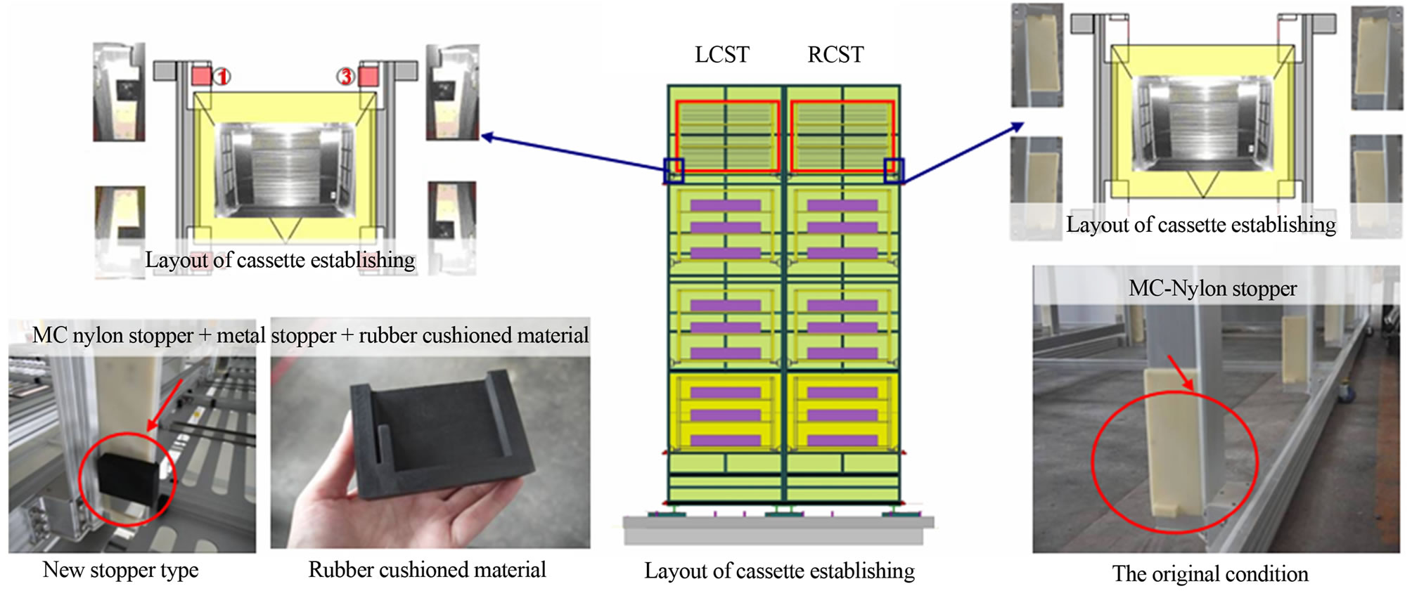
Figure 6. The two forms of MC-Nylon stopper were installed in cassette (the right side CST referred to RCST, the left side CST referred to LCST).
stocker to investigate whether or not the frequency of stocker structure was reduced. The method was used to check whether the internal material caused material damage or loosen at the joint by the experiment. It may also determine whether the experimental specimens damage or not.
The results showed that under the shock wave in PA 400 gal and 600 gal, comparing to the frequency of the specimen after and before the experiment, the frequency of length axle-Y axle was reduced approximately 20%.
The team speculated the reason to be the gravity position of the overall stocker’s center was not located at the center of mass position. It may due to the large amount of FFU fans located behind the cassettes. The fans caused violently torsion in the course of the experiment which led to the Y axle of the structure destroyed.
2.4. Summary
The results of the experiment showed that low stiffness of Stocker storage spaces tends to be violently and structurally displaced. Consequently, it led to large number of PVC boards darted out of the cassettes. In real condition of the high tech factory, the cassettes are used to store large semi-finished or finished glass. Therefore, if the glass was damaged by shocks, it was considered a type of destruction.
The result of frequency-measuring with White Noise analysis showed that after the shock wave in PA 400 gal, the natural frequency of length axle, Y axle, reduced approximately 20%. The possible reason is that the gravity position of the overall stocker’s center was not located at the center of mass position. It caused violent torsion in the course of the experiment which led to the Y axle of

Figure 7. Accelerometer and displacement meter of the installed position.
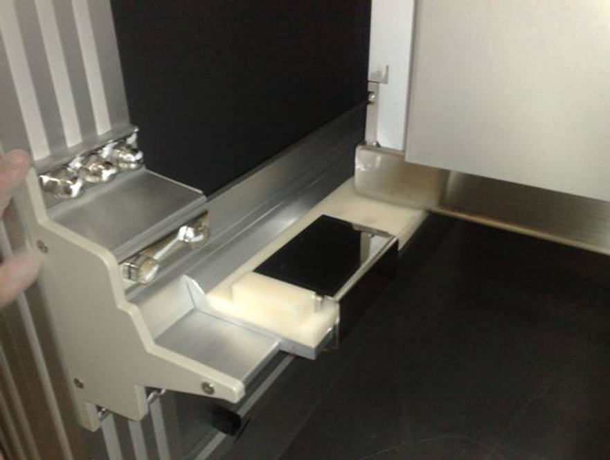
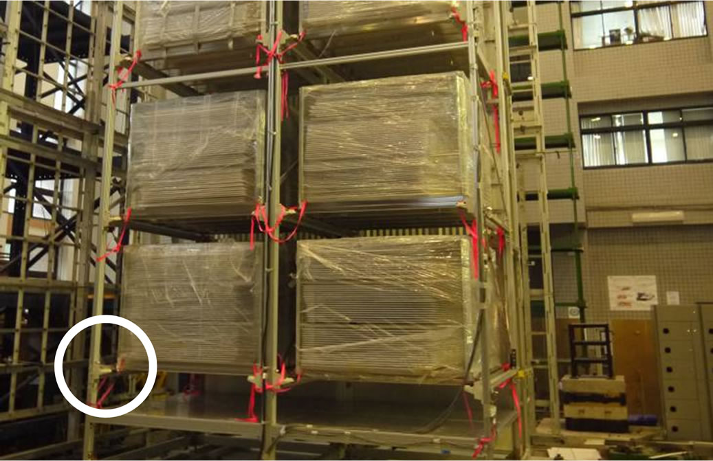
Figure 8. The screw was loosened at the first layer of left cassettes flange with trellis joint.
the structure destroyed. The stocker feet and base were bolted by screws. After specimens removed for inspecttions, a slight deformation was found in the locking of aluminum extrusion materials.
3. The Seismic Tests for after Stocker System Reinforcement
From the results of the experiment of the original machine test, we learned the stiffness of the original Stocker framework design was too low. The structure tended to violently displaced which caused much unpredictable destructions. The team completed 2 kinds of reinforcement test to investigate the seismic behavior: the installation of bracing and the viscous dampers. We expected to enhance the seismic capacity of the original design stocker. The preliminary assessment of experimental results could be discussed to give appropriate proposals for the best reinforcement and to upgrade the seismic capacity.
3.1. Method 1: The Installation of Bracing to Improve the Overall Stiffness
The installation of bracing directly provided the Stocker overall stiffness. It was expected to reduce the shake violently issue of Stocker, and reduce the amount of displacement between layers. The team observed the outcome after the improvement of Stocker, whether it could avoid distortion or skew of the Stocker framework, or cassette falling, and enhance the seismic capacity.
3.1.1. Experimental Equipment and Established
Method 1, the installation of bracing to improve the overall stiffness. The reinforcing braces installed on both sides of the stocker: the bracing section 50 × 100 mm of aluminum extrusion. The locking manner was the L-type angle iron block and T-fixed bolt to lock Stocker scaffold’s aluminum extrusion groove. The installed bracing to improve the Stocker stiffness was shown in Figure 9.
3.1.2. The Result of the Experiment after Installing Bracing
The result of the experiment shown when stocker installed bracing, when PA was 200 gal, due to the force, the link piece showed bending and deformation. The link piece: the L-type angle iron block at the bracing and aluminum extrusion framework groove. When PA was 300 gal, bracing joints loosened in a large number. The reason may due to the size of T-fixed bolt for L-type angle iron block locked being too small. Due to the excessive force, the T-fixed bolt was prone to cause destruction that the T-fixed bolt had been cut and stood idle and could not be removed. On the other hand, the un-loosened T-bolt joints buckled if the bracing loaded with the force. The result of the experiment after installing bracing was the main destruction was at the link piece on the bracing joints and framework. The destruction issue of installed bracing was shown at Figure 10.

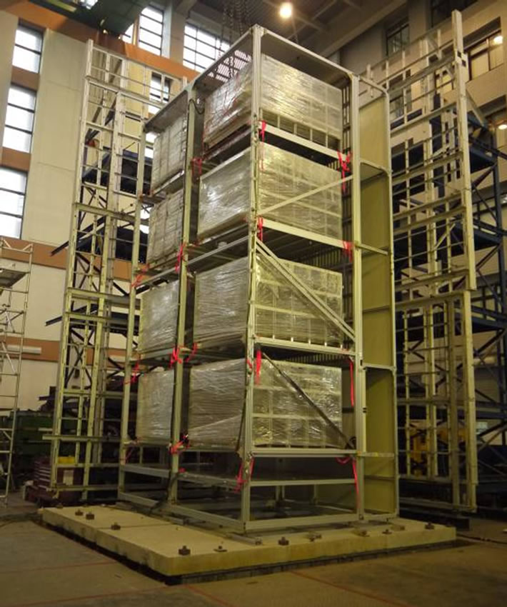
Figure 9. The installing bracing to improve the stocker stiffness.
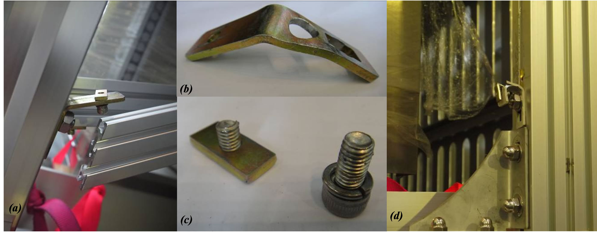
Figure 10. The destruction issue of installing bracing. (a) Bracing joint burst; (b) The link piece, L-type angle iron block, was bended and deformed; (c) T-fixed bolt was cut and stood idle; (d) The main destruction was link piece at the bracing joints and framework.
The possible reasons of destruction were summarized, 1) since the Stocker-D6000 size was bigger, the reinforcement test was relatively too slender; therefore, it could not provide the expected effect of the tensility and compression. 2) The bracing joints were fixed poorly. There were no beams on the top layer of the original Stocker design; damages are prone to occur easily at the line piece, when the bracing loaded force.
3.2. Method 2: The Installation of Viscous Dampers to Improve the Overall Damping Ratio
3.2.1. Experimental Equipment and Established
This pilot study of the seismic capacity was for the low stiffness Stocker system: install the viscous dampers to improve the overall damping ratio. It was expected to enhance seismic capacity and to give concrete proposals for the best reinforcement of upgrading the seismic capacity.
For the preliminary test, the National Earthquake Engineering Research Center provided the existed four sets of fluid viscous damper (FVD), and investigated whether the installation of a damper was a possible reinforcing method. According to the result of the original machine test, the maximum displacement of stocker was at the first layer. Therefore, the team focused on installing the dampers on the outside and inside of the first layer. The installation of the viscous damper was shown in Figure 11.
For installing the four sets of the fluid viscous dampers without increasing stiffness in Stocker; the team designed locking components on the dampers connector. They include: 1) transverse reinforcing beam: 50 (mm) × 50 (mm); 2) extensible square steel tube: 60 (mm) × 30 (mm) × 2070 (mm); 3) designed the damper connector; and 4) design extensible tubes and the joint of the framework.
For the damper only bear the axial force, the damper joint design is as follow: the damper extremity was hinged to the bolt groove. One side of the bolt groove was welded with extensible square tube; the other side of the bolt groove was jointed with 4 T-fixed bolts. The single damper installation condition was shown in Figure 12.
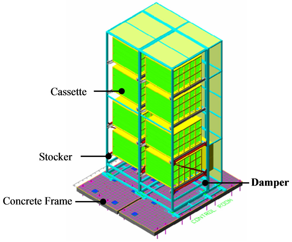
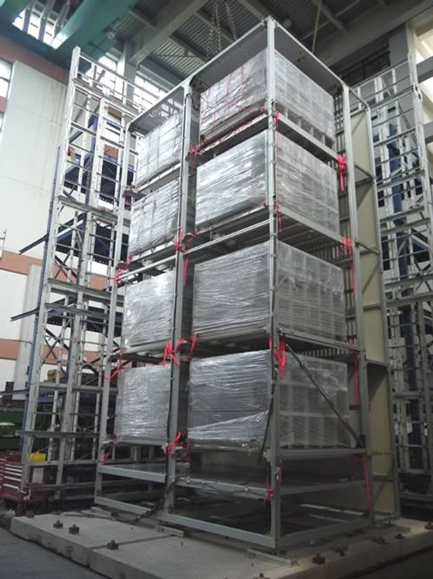
Figure 11. The team installed the dampers focus on the outside and inside of the first layer.
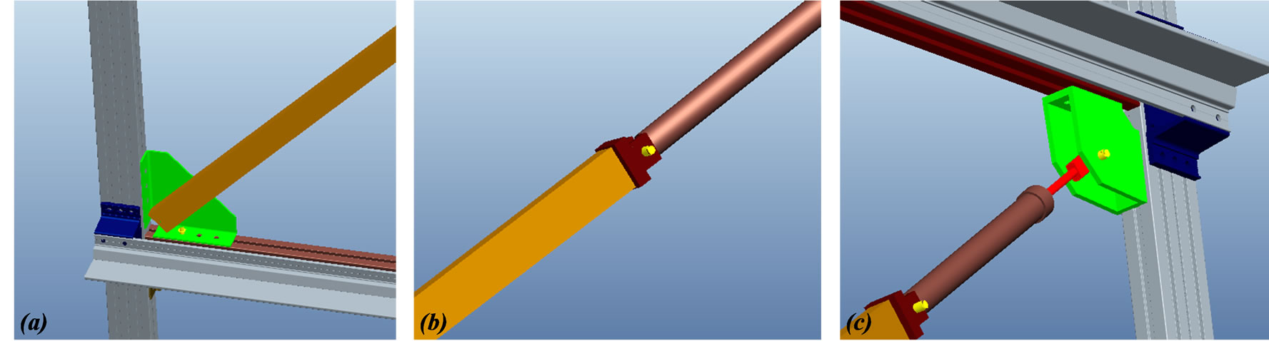
Figure 12. The installation condition of locking components for dampers connector. (a) Design of locking components for dampers connector; (b) Design of installing lower reinforcement beam; (c) Design of installing upper reinforcement beam.
In the experimental specimen, the original StockerD6000 type, the design between second and fourth layer is beamless. To avoid damage at the stocker specimen before experiment, it has not yet receiving force. The team installed a 50 (mm) × 50 (mm) transverse reinforcing beam. The beam was made of the aluminum extrusion material and installed at the damper connector in the stocker framework.
The objective of installing the lower reinforcement beams and upper reinforcement beams was to increase the strength of the Stocker, at the same time, to solve the weakness of the connector between the damper and the Stocker. The damper installation condition was shown in Figure 12.
3.2.2. The Result of Installing the Viscous Damper
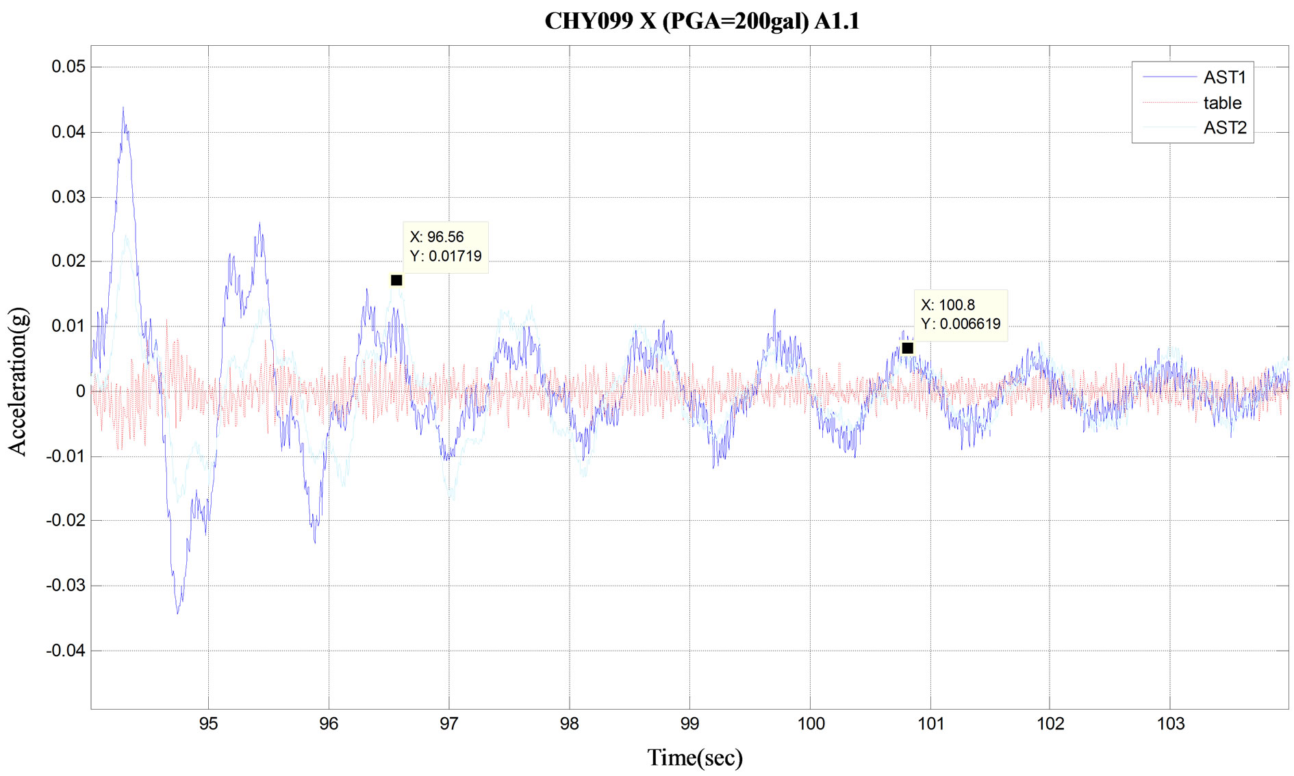
To compare the effect before and after installing damper, the team compared the acceleration of the top layer of the stocker and the shock wave of the shake table in the original machine, and the result of the damping ratio of the original machine was calculated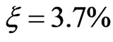 . After installing the damper, by observing the acceleration time history, the response peak of the acceleration was significantly attenuated and the energy demolished. The damping ratio of installed damper was
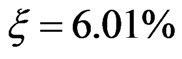 . The top layer of the stocker and the shake table inputted the shake wave was shown in Figure 13.
The experimental result shown in PA for 400 gal, although the top layer cassette slid and collided with the stopper, the stocker structure was not seriously damaged. The preliminary results on increasing seismic capacity showed that the installation of damper was better than installation of bracing for low stiffness stocker. The experimental result shown in PA for 400 gal, although the top layer cassette slid and collided with the stopper, the stocker structure was not seriously damaged. The preliminary results on increasing seismic capacity showed that the installation of damper was better than installation of bracing for low stiffness stocker.
3.3. Summary
The experiment showed that due to enlarger stocker size, the reinforcement method for the installation of bracing, the bracing material or form should use higher stiffness material. The method bolting the joint of the damper also must be improved. The original L-type angle iron block was unable to bear the shear force. When the force from bracing passed to L-type angle iron block, the L-type angle iron block easily deformed. Therefore, it could not function stiffening effectively.
The preliminary observation of reinforcing method was the installation of damper had better effects. The damper was not the best damping ratio of the specimen, so the seismic efficacy was limited. The direction for future research will continue to investigate on the installlation of optimum damping ratio of the damper on the stocker.
4. Results of the Experiment and Comparison
The team investigated the seismic performance of stocker reinforcing measures and assessed the most appropriate reinforcement method.
4.1. Comparison of the Vibration Frequency: Original Machine, Bracing, and Damper
To compare the scanned of natural frequency, the originnal machine without any reinforcement of natural frequency was 0.98 Hz. After installing the damper, the natural frequency was 1.17 Hz. The damper without providing overall stiffness of the Stocker, the natural frequency was closer to the original machine. After installing the bracing, the natural frequency was 1.95 Hz, because the bracing upgraded stiffness of the Stocker. The result of the frequency comparison can preliminarily determine the reliability of the experiment.
4.2. Comparison of the Time History: Original Machine, Bracing, and Damper
In PA for 200 gal, the time history for Stocker at the top layer was compared and shown in Figure 14. From Figure 14, we see the time history of the absolute acceleration shown obviously that the installation of bracing, the acceleration response peak in the sample B-3.67 was the highest. As we can see, upgrading the stiffness of Stocker could increase the acceleration from bottom to top layer. The original machine, A-1.82, and damper, C-2.03, had no significant differences.
Comparison of the relative displacement in time history was shown in Figure 15. The displacement reaction issue, the original machine, sample A, was the highest, followed by installed damper, sample C.
Installed bracing, sample B, canceling out the acceleration response to inhibit the displacement reaction. Therefore, we conclude the bracing has the highest acceleration and the lowest displacement.
By installing the bracing to Stocker enhances the acceleration reaction and inhibits the displacement reaction. However, if the acceleration is too high, the top layer Cassette will outrush of the stocker. Thus, it is not recommended.
The absolute acceleration time history PA was shown in Figure 16. It shows the installation of bracing, sample B, has the highest acceleration response peak, followed by the original machine. The installed damper has the lowest acceleration response peak.
 (a)
(a) (b)
(b)
Figure 13. To compare the acceleration time history of the stocker top layer and shake table inputted the shake wave. (a) The damping ratio of original machine was ξ = 3.7%; (b) The damping ratio of Installation of the damper was ξ = 6.01%.
The preliminary observation of reinforcement method showed that the installed damper did work during earthquakes. However, the damper used in this experiment was not the best damping ratio of the stocker, so the seismic efficacy was limited. Future research will continue to investigate and analyze the stocker character, and
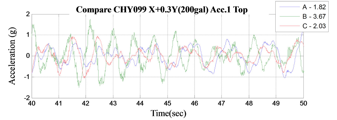
Figure 14. Acceleration time history in PA = 200 gal.
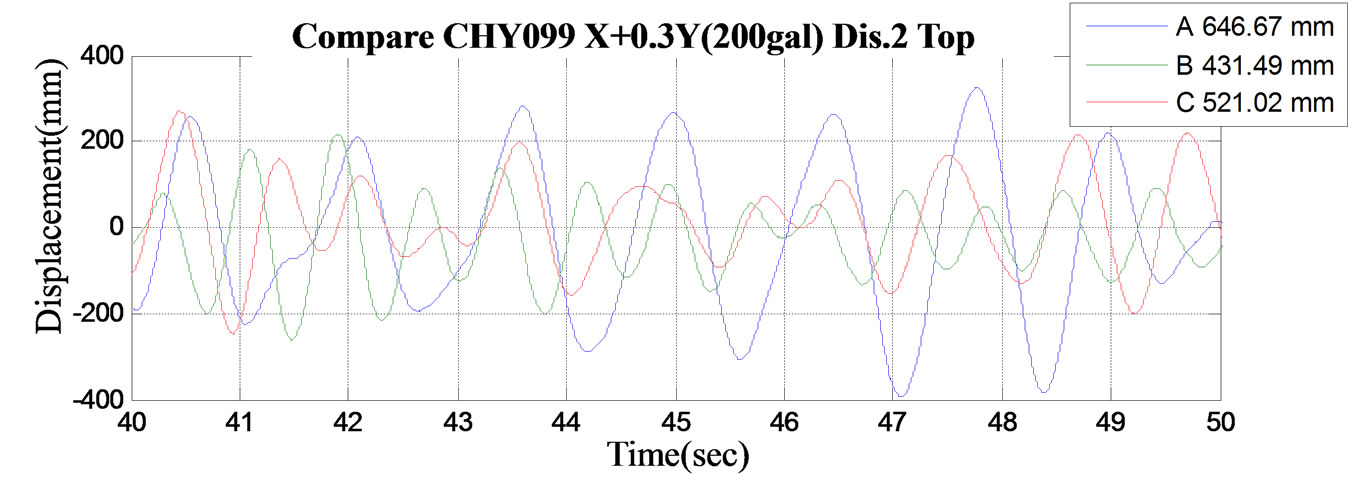
Figure 15. Displacement time history in PA = 200 gal.
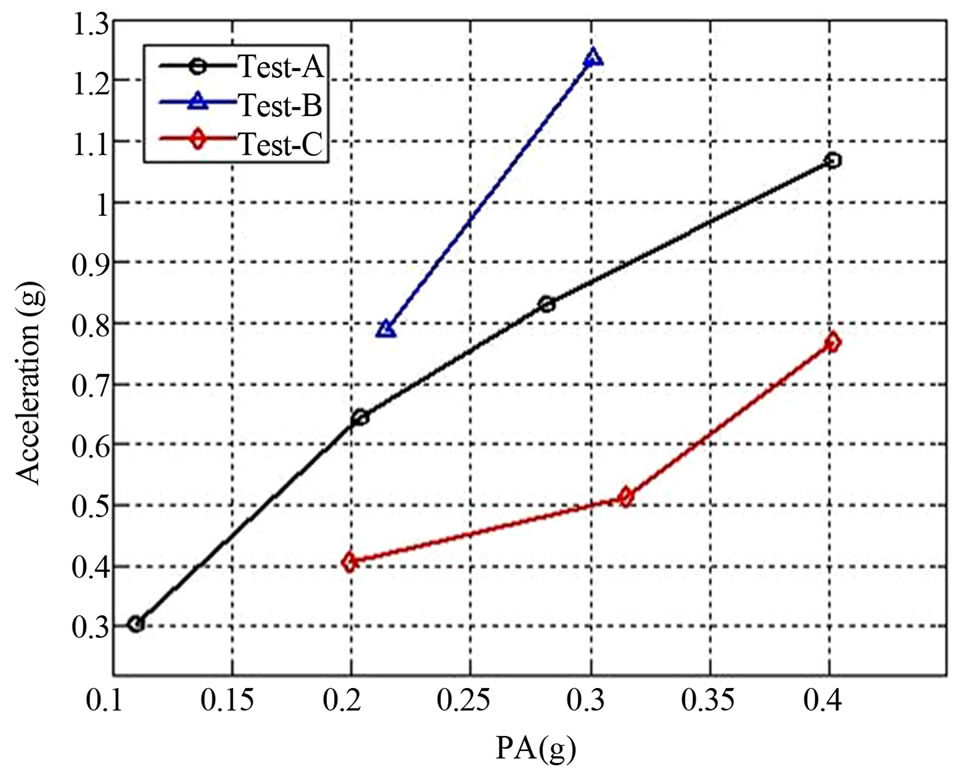
Figure 16. The absolute acceleration time history in the PA data comparison.
choose the optimum damping ratio of damper.
4.3. Comparison of the Maximum of Absolute Acceleration and the Maximum of Relative Displacement: Original Machine, Bracing, and Damper
The result of comparison of the maximum absolute acceleration of the shake table and the top layer of the stocker was shown in Table 1. In PA for 300 gal, acceleration of the top layer of the Stocker: the installed bracing (sample B) was the highest, followed by the
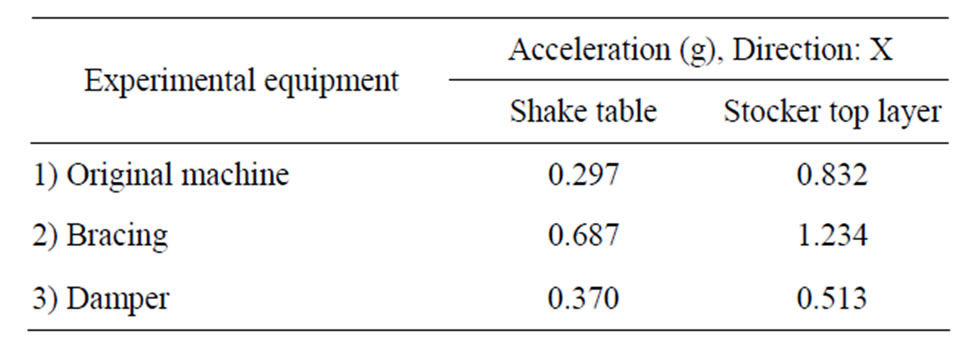
Table 1. Compare the maximum absolute acceleration of the shake table with the stocker top layer in PA = 300 gal.
original specimen (sample A), and the installed damper (sample C) was the lowest.
The result of the comparison of the maximum relative displacement for the shake table and the top layer of the Stocker was shown in Table 2. In PA for 300 gal, the displacement reactions of northwest side (NW-Y) and the southwest side (SW-Y) were different. The reason may due to the large amount of FFU fans behind the cassettes. The FFU fans affected the overall stocker’s position of center-gravity. It caused the overall stocker’s center of gravity position to be not located at the center of mass position which led to the result of maximum relative displacement in the southwest side (SW-Y) being larger than it in the northwest side (NW-Y). The stocker’s gravity position dislocated from the center of mass position was shown in Figure 17.
5. Conclusions
The experimental results of the original machine: Low stiffness of Stocker storage spaces easily tends to be
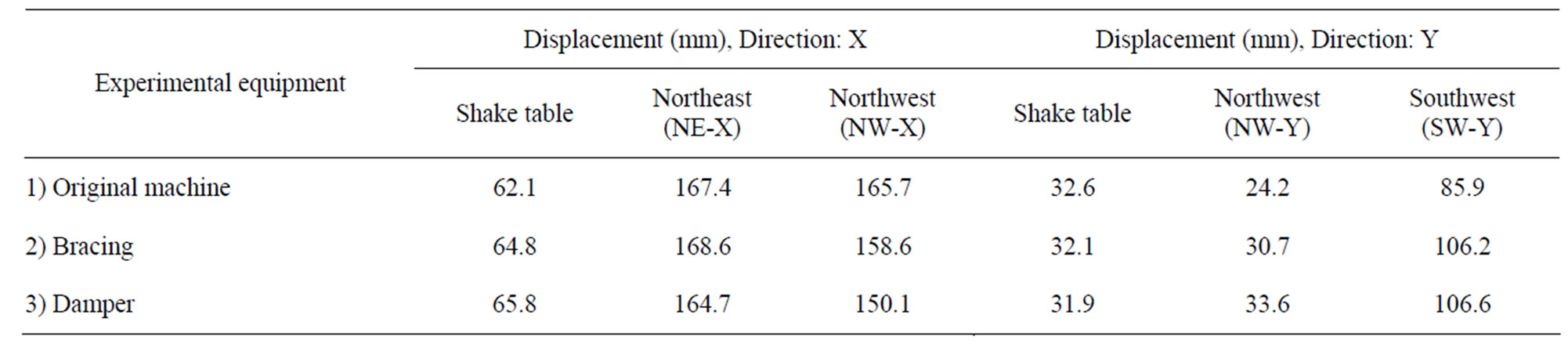
Table 2. Compare the maximum relative displacement of the shake table with the stocker top layer in PA = 300 gal.
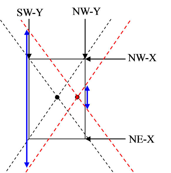
Figure 17. Stocker’s gravity position dislocated from the center of mass position.
violently displaced which causes cassette violently displaced and large number of PVC boards (simulation of glass) slide.
The result of inspected frequency-measuring with White Noise shows that after the shock wave in PA 400 gal, the natural frequency of length axle, Y axle, reduced approximately 20%. The possible reason: the overall stocker’s center of gravity position was not located at the center of mass position. It caused severe torsion in the course of the experiment, which led to the destruction of Y axle of the structure. The Stocker feet and base was anchored by screws. After specimens removed for inspections, we found that there was slight deformation in the locking of aluminum extrusion materials.
The installation of bracing: because the StockerD6000 size was bigger, the material used in bracing in the reinforcement test was relatively too slender. Therefore, it could not provide the expected effect of resisting the tensility and compression. The bracing joints were poorly fixed; there was no beams in the design on the top layer of the original Stocker. Failure at the line piece will occur easily when the bracing loaded with force.
Installing the viscous dampers: the preliminary observation of reinforcement method shown that the effect of installing of damper was better. The damper was indeed effective. However, in this experiment, the damper was not the best damping ratio of the stocker, so the seismic efficacy was limited. Future research will continue to investigate and analyze characters of the stocker and to choose the optimum damping ratio of damper.
Through the comparison of relative displacement, we found that the Stocker’s gravity position was not located at the center of mass position, and it caused severe torsion. In the future, installing tensional component and compressional component on the top layer to link the structure of the stocker can enhance the stability of the stocker system and reduce the effect of eccentric torsion.
The reinforcement method of stocker system: Installing tensional component and compressional component on the top layer to link the structure of the stocker can enhance the stability of the stocker system and reduce the effect of eccentric torsion. In addition, installing the speed type viscous dampers and designing the most appropriate damping coefficient of the damper can reduce acceleration and displacement response of the Stocker and avoid cassette sliding and collision, or glass panel sliding away from cassette.
6. Acknowledgements
In the completion of this study, we would like to express our sincere appreciation to those who have helped and accompanied us during the process of our study. Without their guidance, and support, we would not be able to complete this study.
Our highest appreciation goes to our advisor: 1) Yao George C, professor at department of architecture National Cheng Kung University; 2) Juin-Fu, Chai, National Center for Research on Earthquake Engineering; 3) Wang, Yen-Po, professor at National Chiao Tung University; and 4) Lyan-Ywan Lu, professor at National Kaohsiung First University of Science and Technology, who inspired us to develop the greatest interest in experiment of bracing and damper. Their professional knowledge and intellectual guidance helped us overcome the difficulties in conducting the research and shaped the final version of our study. Without their guidance and encouragement, we might have given it up.
Zhen-Yu, Lin and the members of Metal Industries Research and Development Centre, help us to complete the destruction experiment of Automated Stocker system.
In addition, we are also grateful to lecturer Zoe, who helps us to correct and complete this paper structure in English.
Finally, we are grateful to our team members’ dedication to the study; they are Fu-Chun Huang, Chih-Hsien Lin, Lung-Ho Yeh, Chang Hsun, Wei-Jen Lin, ChihMing Chang, Yu-Ting Huang. With the shockproof expertise and practical experiments, they were consistent learning and their attitude to never giving up and overcoming all the difficulties have made this study happen successfully. We will also strive to work hard and study in the project for the equipment seismic in High-Tech Industry.
REFERENCES
- P.-F. Hsiao, “Aseismatic Application of Fluid Dampers on High Tech. Fab. Structures,” Master Thesis, National Cheng Kung University, Taiwan, 2005.
- J.-C. Wang, C. Yao George, Y.-F. Lin, M.-J. Hsieh, C.-L. Tsai, P.-H. Chen, K.-C. Kuo and W.-T. Chen, “Seismic Experiments and SAP2000 Analytical Study on the Aseismic Footing of Precision Machinery in Hi-Tech Factories,” 2012.
- Chen, W.-C. “A Research on Evaluating Floor Vibration in Earthquakes for Non-Structural Elements Damage Estimate,” National Cheng Kung University, Taiwan, 2008.
- Y.-P. Wang, “Seismic Hazards Mitigation of the HighTech Industries,” Workshop on Protective System for Building Equipments and High-Tech Facilities, 2002.
- C.-L. Chen, “A Study on Seismic Assessment and Vibration Reduction of High-Tech Facilities,” Dissertation, National Kaohsiung First University of Science and Technology, Kaohsiung, 2008.
- K.-B. Lin, “The study of In-Line Stocker Implementation in Large Size Panel Fabrications—A Case Study of TFTLCD Company,” Master Thesis, National Central University, Taiwan, 2007.
NOTES
*Corresponding author.