International Journal of Nonferrous Metallurgy
Vol.2 No.2(2013), Article ID:29909,6 pages DOI:10.4236/ijnm.2013.22005
Effect of Stacking Fault Energy on the Mechanism of Texture Formation during Alternating Bending of FCC Metals and Alloys
South Ukrainian National Pedagogical University after K.D. Ushinskii, Odessa, Ukraine
Email: shkatulyak@mail.ru
Copyright © 2013 Natalia Shkatulyak. This is an open access article distributed under the Creative Commons Attribution License, which permits unrestricted use, distribution, and reproduction in any medium, provided the original work is properly cited.
Received December 21, 2012; revised January 19, 2013; accepted January 26, 2013
Keywords: Stacking Fault Energy; Texture; Alternating Bending
ABSTRACT
Alternating bending shear stresses lead to the formation of twin orientations in the texture of FCC materials with middle and low stacking fault energy (SFE). Only in the stainless steel with a low SFE during alternating bending with different number of cycles components of shear texture {111}
1. Introduction
Most of the modern technologies for processing sheet metal include mechanical and thermal treatment, which inevitably results in the generation of internal stresses in the material and warping of the resulting parts. Therefore, before using coil metal, the metallurgists subject it to straightening on a leveling machine. In the course of straightening, the material is subjected to alternating bending (AB), which ensures good planeness. This treatment minimizes the level of internal residual stresses in the metal and provides necessary planar characteristics, which significantly facilitates the subsequent metal processing and positively affects the quality of finished products. As a result of plastic deformation in the process of straightening, there, of course, occurs a change in the metal texture and microstructure. Mechanisms of metal texture and microstructure formation during the alternating bending, undoubtedly, are due to the stacking fault energy (SFE) value.
The purpose of this research is to establish the regularity of texture and microstructure formation during the alternating bending of aluminum, copper and stainless steel with face-centered cubic (FCC) lattice, which are characterized by high, medium and low SFE, correspondingly.
2. Materials and Methods
2.1. Materials
As the material for the study, strips of aluminum (0.040 Fe, 0.25 Si, 0.07 Zn, 0.05 Ti, 0.05 Mg, 0.05 Mn, 99.5 Al mass. %), copper (0.004 Fe, 0.002 Ni, 0.003 Zn, 0.001 Sn, 0.002 Sb, 0.001 As, 0.003 Pb, 0.003 S, 0.04 O, 99.93 Cu + Ag mass. %) and stainless steel (0.02 C, 18 Cr, 10 Ni, mass. %) were used. The as-delivered aluminum and copper strips 1 mm thick were annealed in a vacuum at 350˚C for 1 h. The as-delivered stainless steel strips 1 mm thick were annealed in a vacuum at 650˚C for 1 h. The process of sheet straightening was simulated with AB using a specially constructed machine. The diameter of the bending roller was 50 mm. The speed of the metal during bending was ~150 mm/s. The samples for texture and structure studies were cut from the initial sheet and from sheets subjected to bending using 0.25, 0.5, 1, 3, and 5 cycles.
2.2. Methods
Before examining the texture, the samples were chemically polished to a depth of 0.1 mm to remove the distorted surface layer. The crystallographic texture was investigated by recording inverse pole figures (IPFs) in the normal direction (ND) and rolling directions (RD) using a DRON-3 m diffractometer in the filtered Mo Kα radiation on both surfaces of the samples after the abovementioned numbers of the cycles and after 0.25 cycle. The sample without texture was produced from fine recrystallized filings of corresponding metal. In order to ensure a flat surface after 0.25 cycle bending for taking IPFs, a composite sample was manufactured from pieces 3 mm wide, which were cut across the metal strips. To take IPFs in the RD, we also produced composite samples.
The metallographic structure was studied in the reflection mode from the butt surfaces of the samples cut in the RD and transverse direction (TD) using microscope Axioplan 2 of the KARL ZEISS Company.
3. Results and Discussion
Figures 1-3 show some IPF ND of Al, Cu and stainless steel respectively. Figures 4-6 show the relevant microstructure of Al, Cu and stainless steel.
3.1. The Initial Texture and Microstructure
The texture of initial Al sample is represented mainly of cube orientation {001}〈100〉 with the scattering and of
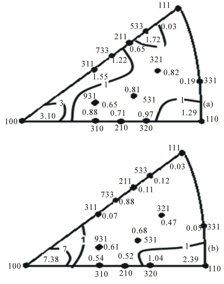
Figure 1. IPF ND of Al samples in the initial state (a) and after 5 cycles of alternating bending (b).
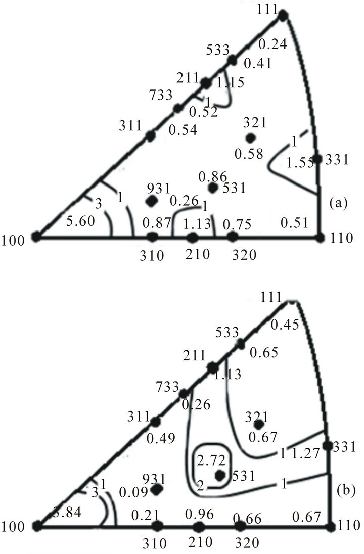
Figure 2. IPF ND of Cu samples in the initial state (a) and after 5 cycles of alternating bending (b).
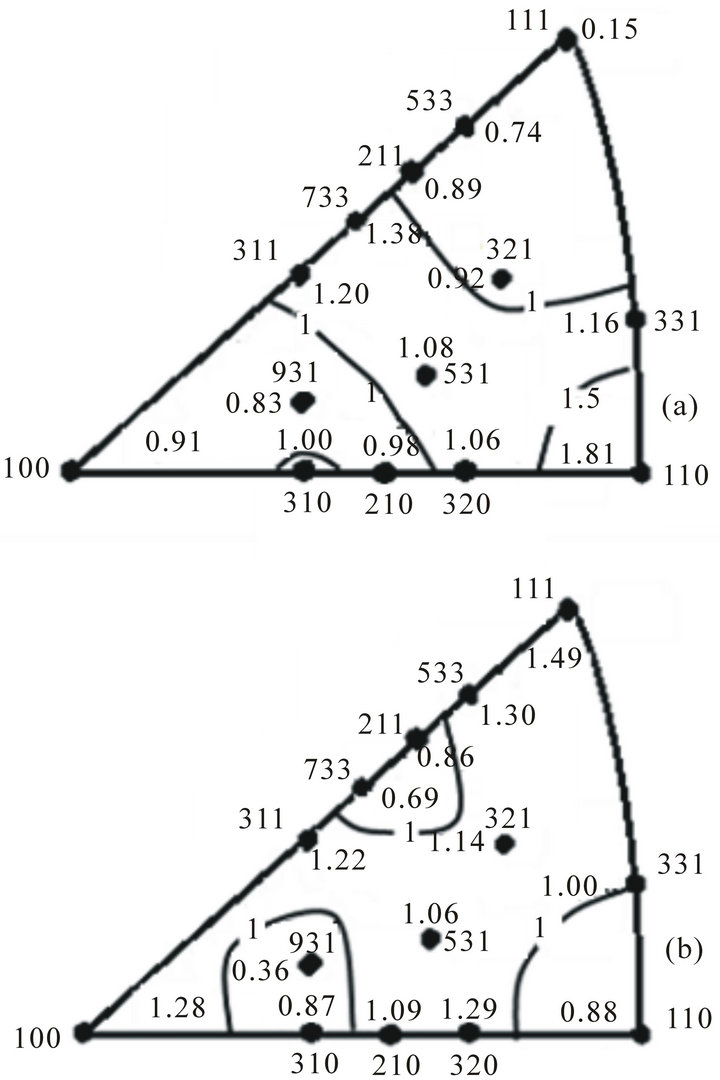
Figure 3. IPF ND of stainless steel samples in the initial state (a) and after 5 cycles of alternating bending (b).
 (a)
(a)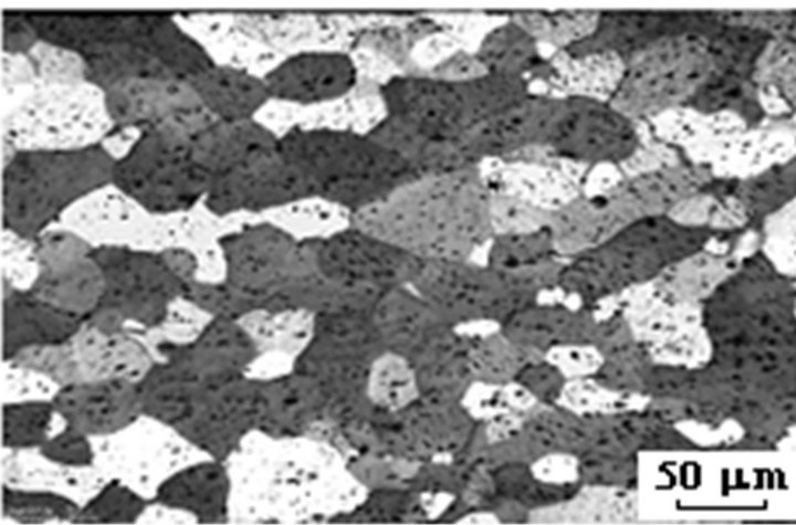 (b)
(b)
Figure 4. The microstructure of the cross section perpendicular to the ND of Al samples in the initial state (a) and after 5 cycles of alternating bending (b).
 (a)
(a)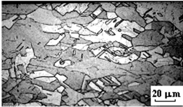 (b)
(b)
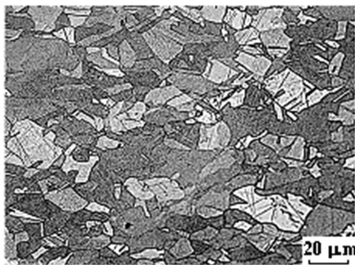
Figure 5. The microstructure of the cross section perpendicular to the ND of Cu samples in the initial state (a) and after 5 cycles of alternating bending (b).
Goss orientation {110}〈100〉. The cube texture of the most frequently found during recrystallization of rolled aluminum. Goss orientation formed in aluminum rolled with the small (~30%) and medium (~50% - 70%) de-
 (a)
(a) (b)
(b)
Figure 6. The microstructure of the cross section perpendicular to the ND of stainless steel samples in the initial state (a) and after 5 cycles of alternating bending (b).
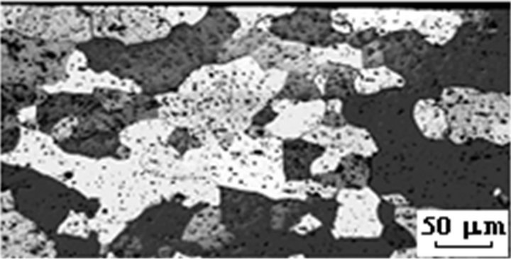
formation ratio [1]. Saving Goss texture after recrystallization annealing of aluminum is usually associated with the recovery process. This process is also called recrystallization “in situ”, since the texture does not change by annealing [2]. The microstructure of initial sample (Figure 4(a)), consisting of relatively large grains (>50 micrometers), is typical of recrystallization [2]. Thus, the original sample is recrystallized after annealing at 350˚C, 1 h [3].
It is seen (Figure 2(a)), the texture of initial sample Cu is represented mainly by cube {001}〈100〉 orientation and by the remains of the rolling texture {112}〈111〉. Also present orientations {012}〈120〉; {012}〈121〉; {012} 〈100〉; {012}〈123〉; {331}〈110〉; {331}〈013〉; {331}〈123〉. In the corresponding micrographs (Figure 5(a)), annealing twins are observed. The presence of a cube orientation in the annealing texture and of annealing twins in corresponding micrographs indicates that the initial material was recrystallized [4,5]. The formation of the above cube orientations and {012}〈uvw〉 texture components during copper recristallization, as was described in the earlier work [6], can be activated by untwinning of the rolling texture component {112}〈111〉 through the inverse Rowland transformation. Later, this has also been demonstrated upon the recrystallization annealing of preliminarily rolled copper bicrystals with the initial twin orientations 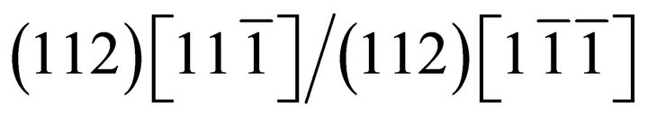 and
and 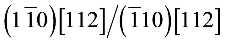 in [7]. The formation of the {331}〈uvw〉 orientations was described in the study of texture in copper rolled to 90% (in thickness) and annealed for half-hour at 250˚C [8]. Together with the cube component, the recrystalliization texture of copper contains {122}〈212〉 orientations, which are twinned with respect to the cube orientation [9,10]. As was said above, twins in the copper microstructure were found in our study as well (Figure 5(a)). On the one hand, it is impossible to quantitatively analyze 〈221〉 poles in the IPFs of an FCC metal because of the ambiguity of their indexing (superposition of 511 and 333 reflections, and 600 and 442 reflections). On the other hand, the 〈221〉 directions are deviated from 〈331〉 directions shown in the IPFs by an angle of ≈6.3˚. In [11], the authors performed a thorough analysis of twin maxima in direct experimental pole figures in a coarse-grained rolled copper with grain sizes of 50 and 500 μm and in a fully annealed copper. The analysis has shown that the exact location of the twin maxima in the pole figures deviates from the ideal positions of {122}〈212〉 twins by 2˚ - 3˚ to 9˚, depending on the degree of preliminary rolling. This makes it possible to suppose that our original micrographs of the initial recrystallized copper sample depict annealing twins with orientations close to {122}〈212〉, which in the IPFs corresponding to the normal direction (ND) lie in the region of spread of the 331 pole.
Texture analysis of initial sample stainless steel (Figure 3(a)) showed that the texture consists of two limited axial components. The first component with the axis 〈110〉 parallel to the ND runs from {011}〈100〉 to {011}〈112〉. The second component with the axis 〈110〉 that is inclined at about 60˚ to ND extends from ~ {112}〈111〉 through {135}〈211〉 to {011}〈112〉. The development of these two limited axial components corresponds to Taylor prediction model based on normal octahedral sliding [12,13]. In addition there are the twinning orientation {113}〈211〉, formed probably by annealing [4]. The microstructure of steel consists of equiaxed grains of size of ~50 microns. The grains contain twins of recrystallization after annealing at 600˚C (Figure 4(a)).
3.2. Effect of Alternating Bending
Texture is changed after deformation by alternating bending with different number of cycles. For interpretation of texture changes is suggested the following deformation model. Grains in the layers of metal on the convex side of the sample are exposed to tensile stresses when bending to one side (1/4 cycles). At the same time, on the concave side of the sample appear the compressive stresses. As a result of the opposite sign stresses in the strip can occurs shear strain. Thus, the shear strains arised at alternating bending of metal strip can lead to the formation in FCC metals and alloys of shear components texture such as [14]: A—{111}〈hkl〉; B—{hkl}〈110〉; C—{001}〈110〉. Designations {hkl}〈uvw〉, listed here, indicate that the plane {hkl} coincide with the shear plane, and the directions 〈uvw〉 coincide with the shear direction. In addition, the twinning should play a significant role in the presence of alternating sign shear stress components. Therefore, should expect of the development of twin orientations during the alternating bending, all the more that as is knows the role of twinning is grows in materials with lowering their SFE [15].
3.3. Effect of Stacking Fault Energy
It was found that the textures of different investigated metals after deformation by alternating bending are significantly different (Figures 1-3 and Table 1).
During the alternating bending of aluminum, which has high stacking fault energy, occurs a dynamic recovery. The type of the initial crystallographic texture
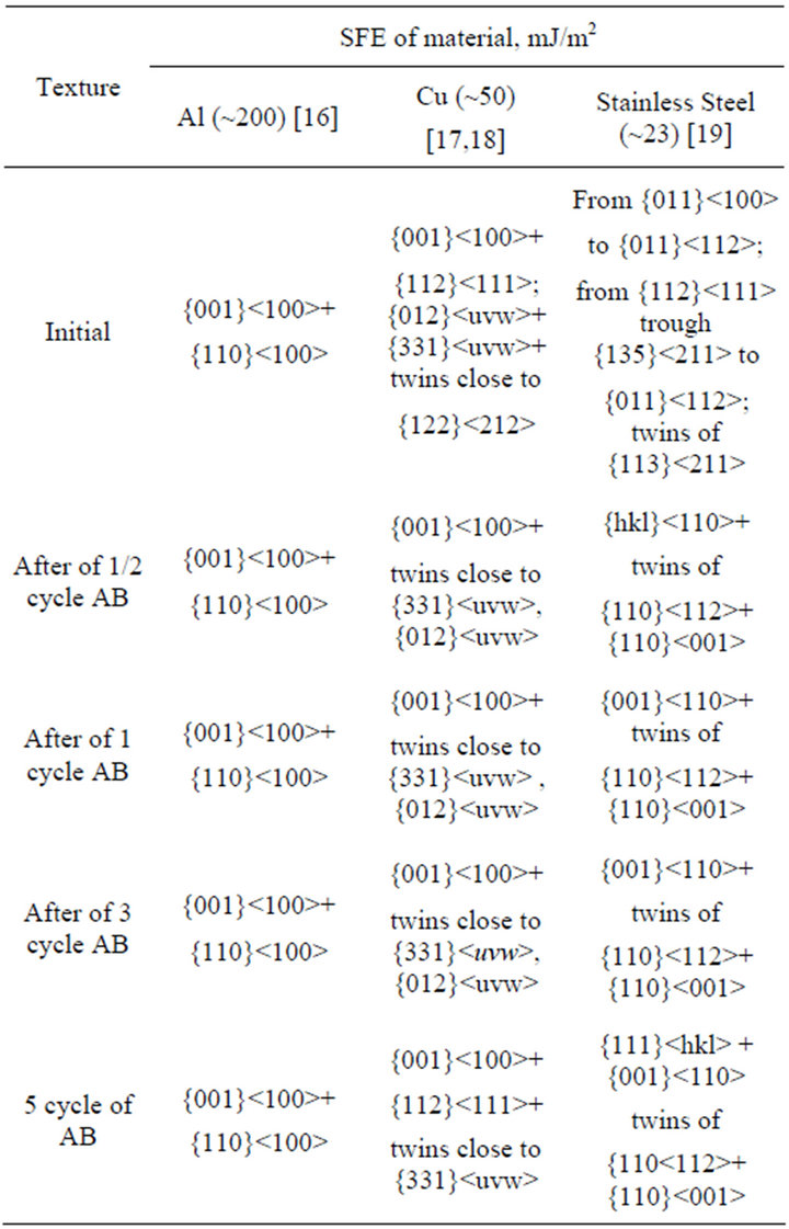
Table 1. Texture acquired during the bending of the metal and alloys with differ SFE.
{001}〈100〉 + {110}〈100〉 does not change (Figures 1(a) and (b)). The share of cube texture with the increases of cycle’s number of alternating bending increases and reaches its maximum after three cycles. Share of component of the texture Goss increased slightly. This is due to the fact that high stacking fault energy (aluminum and bcc metals) contributes to a very fast kinetics of static and dynamic recovery. In these metals climb and cross slip of dislocation rarely happens. The recovery (static or dynamic) reduces the density of crystalline defects and driving force of recrystallization. In the initial phase, for small strains, dislocations interact and multiply. With an increase of dislocation density during the increasing of strain will grow the driving force and, therefore, the share of recovered material with developed microstructure of low-angle boundaries and sub-boundaries. For strains higher than the critical strain , the degree of strain hardening and recovery achieved of dynamic equilibrium, at where remains unchanged the disorientation and average size of equiaxed subgrains (steady state), which are a function of the level of strain and temperature [20]. This is confirmed by corresponding images of microstructure that is representing oneself equiaxed grains, as in the original sample. Deformation of aluminum and aluminum alloys at the room temperature is called often the cold deformation. However, since aluminum melting temperature (Tm) is quite low, the deformation at room temperature (0.33 Tm) is close to the warm deformation (0.4 Tm - 0.6 Tm). Alternating bending in our study occurs at a rate of deformation 0.2 s−1. Heat, which released during deformation at the room temperature, warms the material. This brings closer the conditions of deformation to the warm mode.
Some overall reduction in the pole density in the IPFs of Cu is observed after bending of 0.25 cycles, which indicates about increased spread of texture. With an increase in the number of AB cycles to three, the number of twins tends to increase in the corresponding micrographs. This is accompanied by an increase in the pole density at the 210 and 331 points in the IPFs taken in the ND. The bending deformation can be simulated as a combination of tension of the convex side and compression on the concave side of the strip. The authors of [4] have analyzed the possibility of deformation induced twinning in FCC metals under tension and compression. It was shown that, since the twinning in the FCC structure is always preceded by slip [4], the twinning plane is , and that Shockley and Frank partial dislocations are formed [4] in the process of twinning. These partials act as twinning dislocations under compression for the initial orientations that in the unit triangle of the standard stereographic projection are adjacent to the 011 pole, and, under tension, for the orientations adjacent to 001. Thus, under compression, we should expect the formation of twins with orientations that lie near the 331 pole; and under tension, in the region bounded by the 210, 931, 311, and 211 poles [4]. These orientations are present in our IPFs, as was mentioned above. Thus, in the AB process there occurs deformation induced twinning, which becomes somewhat weaker as the number of AB cycles increases to 5 (Figure 5(b)). Cubic texture and pole density of twins orientation are weakens after increasing the number of cycles of alternating bending to 5, and formed component of deformation texture of type {135}〈211〉 (Figure 2(b)).
It was found that only the stainless steel, which has a low SFE, results in formation of various combinations of initial rolling texture, shear components at a different (small) number of cycles of alternating bending. These are: A—{111}〈hkl〉; B—{hkl}〈110〉; C—{001}〈110〉 and twins orientations (Figure 6(b)). The shear texture component A is formed after bending on 1/4 part of cycle on both sides of stainless steel specimen. After bending on 1/2 part of cycle on the one side of stainless steel sample is formed component B of shear texture. There are also orientations of twinning, which form the orientations of texture {110}〈112〉 and {110}〈001〉 in metals and alloys with low SFE [11,12]. In the sample after 1 cycle of alternating bending is formed component C of shear texture. At the same time, on the opposite side of the same sample is observed orientation of initial texture. The twinning orientations, as in the previous case also take place. After three cycles of alternating bending on the one side of specimen is formed texture that is similar to the initial texture. Texture on the opposite side the same specimen is represented fairly intense shear texture component C. The shear components A and C characterize the texture on the one side of stainless steel specimen after five cycles of alternating bending. Region of high pole density on IPF significantly increased in comparison with the other samples that probably due to the formation of twin orientations [4]. Texture the same specimen on the opposite side is characterized by the formation of shear component of the texture and twinning orientations. In general, the scattering texture increased compared to initial state if you take into account the both surface of stainless steel strip after 5 cycles of bending.
A common feature of the studied materials is that the most significant change in texture and structure occur within the first three to five cycles of alternating bending.
4. Conclusions
Thus, it is shown that in the presence of shear stress components of opposite sign during the process of alternating bending the mechanism of the texture formation of FCC metals depends on the stacking fault energy of material.
In aluminum that is characterized of high stacking fault energy and a low melting point, the process of recovery occurs. The share of cubic component in the texture with the number of cycles of alternating bending increases and reaches a maximum after three cycles. The share component of the texture Goss increased slightly.
In copper, which is material with an average of stacking faults energy, during the alternating bending the deformation twinning process occurs, which is developed most rapidly during the first three cycles of alternating bending. Increasing the number of cycles to 5 leads to a weakening of the texture of the cube and the pole density of twinning orientations and development of deformation texture of type {135}〈211〉.
Only stainless steel strips, which have a low stacking fault energy, result in formation of various combinations of initial texture, components of shear texture at a different (small) number of cycles; these are {111}〈hkl〉, {hkl}〈110〉, {001}〈110〉 and twinning orientations.
The most significant change in texture and structure occur within the first three to five cycles of alternating bending.
REFERENCES
- W. M. Mao, “Influence of Rolling Reduction on Recrystallization Texture in Commercially Pure Al,” Journal of Materials Science & Technology, Vol. 6, No. 4. 1990, pp. 257-262. http://www.jmst.org/EN/abstract/abstract15490.shtml
- F. J. Humphreys and M. Hatherly, “Recrystallisation and Related Annealing Phenomena,” Elsevier, Oxford, 2004, 628 p.
- N. M. Shkatulyak and N. P. Pravedna, “Effect of Alternating Bending at the Texture, Structure and Mechanical Properties of Aluminum Sheets,” Metallovedenie i Termicheskaja Obrabotka Metallov, Vol. 34, No. 2, 2012, p. 209 (in Russian).
- Y. D. Vishnyakov, A. A. Babareko, S. A. Vladimirov and I. V. Egiz, “Teoriya Obrazovaniya Tekstur v Metallakh i Splavakh (Texture Formation Theory in Metals and Alloys),” Nauka, Moscow, 1979, 343 p (in Russian).
- N. M. Shkatulyak, A. A. Bryukhanov, M. Rodman, V. V. Usov, M. Schaper, G. Haferkamp and V. A. Nastasyuk, “Reverse Bending Effect on the Texture, Structure, and Mechanical Properties of Sheet Copper,” The Physics of Metals and Metallography, Vol. 113, No. 8, 2012, pp. 810-816. doi:10.1134/S0031918X1208011X
- C. A. Verbraak, “The Formation of Cube Recrystallization Textures by 112 Slip,” Acta Metallurgica, Vol. 6, No. 9, 1958, pp. 580-597. doi:10.1016/0001-6160(58)90100-7
- W. F. Hellerph, C. A. Verbraaks and B. H. Kolster, “Recrystallization at Grain Boundaries in Deformed Copper Bicrystals,” Acta Metallurgica, Vol. 32, No. 9, 1984, pp. 1395-1406. doi:10.1016/0001-6160(84)90085-3
- T. Kamijo “Study on the Inverse Rowland Mechanism for the Nucleation of a Cube Recrystallization Texture,” Journal of the Japan Institute of Metals, Vol. 31, No. 6, 1967, pp. 741-746. http://www.jim.or.jp/journal/j/31/06/741-746.html
- W. Mao, “Formation of Recrystallization Cube Texture in High Purity Face-Centered Cubic Metal Sheets,” Journal of Materials Engineering and Performance, Vol. 8, No. 5, 1999, pp. 556-560. doi:10.1007/s11665-999-0009-3
- K. Sztwiertnia, “Orientation Aspects of the Recrystallization Nucleation in Highly Deformed Polycrystalline Copper,” Materials Science Forum, Vol. 467-470, 2004, pp. 99-106. doi:10.4028/www.scientific.net/MSF.467-470.99
- M. Sindel, G. D. Kohlhoff, K. Lücke and B. J. Duggan, “Development of Cube Texture in Coarse Grained Copper,” Textures and Microstructures, Vol. 12, No. 1-3, 1990, pp. 37-46. doi:10.1155/TSM.12.37
- C. D. Singh, V. Ramaswamy and C. Suryanarayana, “Development of Rolling Textures in an Austenitic Stainless Steel,” Textures and Microstructures, Vol. 19, No. 1- 2, 1992, pp. 101-121. doi:10.1155/TSM.19.101
- C. D. Singh, “On the Development of the Brass-Type Texture in Austenitic Stainless Steel,” Textures and Microstructures, Vol. 22, No. 1, 1993, pp. 59-72. doi:10.1155/TSM.22.59
- G. R. Canova, U. F. Kocks and J. J. Jonas, “Theory of Torsion Texture Development,” Acta metal., Vol. 32, No. 2, 1984, pp. 211-226. doi:10.1016/0001-6160(84)90050-6
- E. B. Tadmor and N. Bernstein, “A First-Principles Measure for the Twinnability of FCC Metals,” Journal of the Mechanics and Physics of Solids, Vol. 52, No. 11, 2004, pp. 2507-2519. doi:10.1016/j.jmps.2004.05.002
- L. E. Murr, “Interfacial Phenomena in Metals and Alloys”. Addison-Wesley Pub. Co., 1975. 376 p.
- J. A. Venables, “The Electron Microscopy of Deformation Twinning,” Journal of Physics and Chemistry Solids, Vol. 25, No. 7, 1964, pp. 685-690. doi:10.1016/0022-3697(64)90177-5
- Y. H. Zhao, X. Z. Liao, Y. T. Zhu, Z. Horita and T. G. Langdon, “Influence of Stacking Fault Energy on Nanostructure Formation under High Pressure Torsion,” Materials Science and Engineering: A, Vol. 410-411, 2005, pp. 188-193. doi:10.1016/j.msea.2005.08.074
- G. R. E. Schramm and R. P. Reed, “Stacking Fault Energies of Austenitic Stainless Steels,” Metallurgical Transactions A, Vol. 6, No. 7, 1974, pp. 1345-1351. doi:10.1007/BF02641927
- E. Totten and D. S. Mackenzie, “Handbook of Aluminum: Alloy Production and Materials Manufacturing,” Marcel Dekker Inc., New York, Basel, 2003.