Open Journal of Regenerative Medicine
Vol.1 No.1(2012), Article ID:20439,8 pages DOI:10.4236/ojrm.2012.11002
Generation of biomaterial particles with controlled dimensions via electrospraying
![]()
1Department of Materials Science and Engineering, Zhejiang University, Hangzhou, China; *Corresponding author: xiang.li@zju.edu.cn
2Department of Mechanical Engineering, University College, London, UK
3Department of Materials Science and Metallurgy, University of Cambridge, Cambridge, UK
Received 5 April 2012; revised 20 May 2012; accepted 13 June, 2012
Keywords: Electrospraying; Hydroxyapatite; Nozzle Geometry Effect
ABSTRACT
It is well known that small biomaterial particles can lead to superior properties demanded by advanced applications in tissue engineering. Electrospraying has been considered as a promising approach to prepare fine particles, but reducing the particle size during such jetting process is always challenging. This is because the size of the as-sprayed particles is always limited by the device outlet diameter used. In the study we show that hydroxyapatite (HA) relics of 2 - 3 μm with low standard deviation can be deposited using a large nozzle (diameter of 1100 μm) only by reducing the nozzle tip angle from 90˚ to 15˚. The mechanism of such phenomenon was extensively discussed, and a range of refined HA patterns were successfully prepared using the updated electrspraying configuration. We anticipate our findings to have a significant impact on the research of nanostructured biomaterials with superior properties which are realized by reducing the particle size using a greener electrically-driven processing technique.
1. INTRODUCTION
In contemporary biomaterials processing it is becoming more and more desirable to achieve even smaller particles to obtain superior material properties by generating carefully controlled microstructures [1-3]. Electrospraying has been considered as a promising technique to prepare fine particles with controlled dimensions, which are generated from the as-sprayed solution droplets. In order to reduce the droplet size, a nozzle of the smallest diameter is always used to limit material flow [4]. However, generally, the tiny nozzle is more likely to induce cumbersome operational procedures, such as typical nozzle blockage, vibration etc., and this is a significant drawback in automated mass production.
It is of vital importance to understand the underlying science of electrospraying before utilizing it wisely. Almost a century ago, it was found that liquid flow under an electric field can be dispersed into tiny droplets [5]. Following the finding, Taylor gave a quantitative analysis on this phenomenon in 1964. He demonstrated that the formation of the liquid cone under the electric field is due to the balance of electrostatic pressure and capillary pressure in the liquid surface [6]. This mode may be obtained with the liquids of highly varied conductivities. The production of aerosols within a range of droplet sizes, including the submicrometre range, could be easily achieved under this mode. Nowadays, the characteristic of such phenomenon has attracted the physician’s attention worldwide. The term “electrohydrodynamic atomization (EHDA)” or “electrospraying” of liquids has therefore been coined to describe the form of atomization that occurs from a steady conical meniscus as opposed to other forms of atomization. In the end of last century, when the time of nanotechnology arrived, and the mechanism of electrospraying was systematically studied as a novel materials engineering technique. A physical model was built to demonstrate the process of the cone-jet mode. The first is the acceleration of the solution in the cone [7]. This acceleration process and the shape of the cone are a result of the balance of many factors, e.g. liquid pressure, liquid surface tension, viscosity and electric stresses. The creation of a permanent jet requires a penetration of the electric field lines in the liquid. Only this penetration allows the appearance of a component of the electric field tangential to the liquid surface, which is acting on the surface charges, creates a force which drives the liquid and an acceleration of the jet downstream [8]. The second phase is the jet break-up, which is actually a droplet production process. Two mechanisms can lead to the liquid emission from the tip of a cone-jet mode. In one mechanism, ions, neutral atoms and droplets are emitted from the liquid surface due to instabilities brought on by the intense electric field at the tip. Or, in the other mechanism, liquid is ejected via the formation of liquid jet which breaks into droplets after some length [9] due to surface instabilities [10]. The third phase is the evolution of the spray after the droplet production. As a coating technique, the droplet size achieved is crucial for its applications. Under the conejet mode spraying, the electrical interaction between the highly charged droplets occurs and droplet fission can change its size distribution. Smaller droplets are found at the edge of the spray, and the larger sized droplets present in the centre of spray [11,12]. The dependence of the main droplet size on the liquid flow rate in the cone-jet mode was also studied by Canan-Calvo in 1997. Scaling laws, a mathematic model he developed, demonstrated the relationship between the main droplets size and volume flow rate [13]. Another impact for the liquid droplet size produced is the liquid phase evaporation in the droplets. It depends on many aspects, e.g. solvent properties, humidity, air movement, environment temperature [14]. In 1978, Rayleigh observed a droplet fission phenomenon on the highly charge droplets. A Rayleigh charge limit, above which the droplet fission process occurs, was also defined [15]. In another word, a droplet could segregate into several smaller droplets if the over-limited charge presents in the droplet surface.
Based on the mechanism research of electrospraying, this process had been widely used for biomedical purposes in the past decades. In 1989, it was pioneered for mass spectroscopy of large biomolecules by Fenn [16]. Since then, it had also been used as a coating technique for a number of other functional material thin films [17-19]. In the early 21st century, electrospraying was used as a novel process technique to prepare uniform coatings of hydroxyapatite (HA, Ca10(PO4)6(OH)2), which has been proven to the most similar mineral phase of natural bone [20], on metallic implant materials to enhance the bonding between the conventional implant and natural bone tissue [21]. It was also developed into other techniques, such as 3-D printing [22], template-assisted electrohydrodynamic atomization (TAEA) technique [23] for bioactive HA patterns to up-regulate cellular behavior. The research and development of electrospraying for other biomedical applications is still steadily on-going.
However, to the best of our knowledge, the influence of nozzle geometry, a vital factor for the electric field for forming the cone-jet mode electrospraying, has not yet been uncovered systematically. It was only briefly mentioned that “the geometry of the nozzle influences the cone-jet domain drastically” [19]. Therefore, to further understand and better utilize electrospraying, this study will quantitatively investigate the influence of the nozzle tip angle to the stability of cone-jet mode electrospraying and the relic size distribution produced, which both are significant for the biomaterial coating and patterning process. In addition, TAEA process with the refined experimental configuration will carried out to verify its impact on the HA patterning procedure.
2. MATERIALS AND METHOD
2.1. Materials
HA was synthesized by a precipitation reaction between calcium hydroxide and orthophosphoric acid. Both reagents were AnalaR grade. 0.3 M orthophosphoric acid was added drop-wise to a 0.5 M calcium hydroxide solution under continuous stirring at room temperature, while the pH was kept above 10.5 by the addition of ammonia solution. Stirring was maintained for further 16 hours after complete addition of the reactants. The precipitate obtained was aged for a further week and then washed with boiling water. To make the HA suspension suitable for electrospraying, ethanol was added as a liquid carrier until the 3% wt concentration achieved. To investigate the influence of nozzle tip angle to the stable cone-jet domain, such HA suspension was used as the spraying liquid during the process.
2.2. Experimental Configuration and Procedure
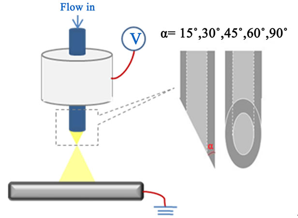
As shown in Figure 1(a), basically, the setup consists of a ground electrode and a nozzle, which is connected to a high voltage supply (Glassman Europe Ltd., Tadley, UK). The liquid is fed to the nozzle by an infusion pump (Harvard apparatus PHD 4400) at a controlled flow rate. The flowing medium is subjected to an electrical field, which is generated by the applied voltage between the nozzle and the ground electrode. Five different stainless steel nozzles were designed for the study. The nozzle tip angle varies from 15˚ to 90˚, as shown in Figure 1(a). The internal and the outer diameter of the nozzles are 800 μm and 1100 μm, respectively.
To investigate the influence of nozzle tip angle on the stability of the cone-jet mode electrospraying, the nozzles afore-mentioned were used. In these experiments, the nozzle tip to substrate distance was kept at 40 mm. HA suspension (3 wt%) was syringed to the nozzle, and the flow rate was varied from 5 μl·min-1 to the maximal value for stable cone-jet mode spraying. The applied voltage between the nozzle and the ground electrode was varied up to 7 kV to establish the modes of electrospraying. A high speed digital camera (Weinberger AG, Dietikon, Switzerland) in conjunction with a computer was used to observe and characterize the cone-jet mode. At a chosen flow rate, the cone-jet mode was achieved within a range of applied voltage. Thus, the relationship between the applied voltage and flow rate for the suspension jetting in the cone-jet mode was established. To compare and confirm the results got from the HA suspension, pure ethanol, which had been proven to give a stable cone-jet mode spraying, was also used as the process liquid with the same procedures.
To investigate the influence of nozzle tip angle on the deposited relic size distribution, HA suspension was syringed into five different nozzles. The nozzle tip-ground electrode distance and liquid flow rate were set at 40 mm and 10 μl/min, respectively. Microscope glass slides were used as substrates to collect the deposited relics. The collecting time was controlled at 10 seconds. Three deposited glass slides were prepared for each nozzle. The relics collected on the glass slides were then examined using an optical microscope. 50 relics on each glass slide were stochastically chosen and measured.
2.3. Taea Patterning Process
Due to the importance of the relic size to TAEA patterning process, as reported previously [23], the nozzle which gives the smallest relics was used for TAEA patterning process (Figure 1(b)) to verify the findings. Pure
 (a)
(a)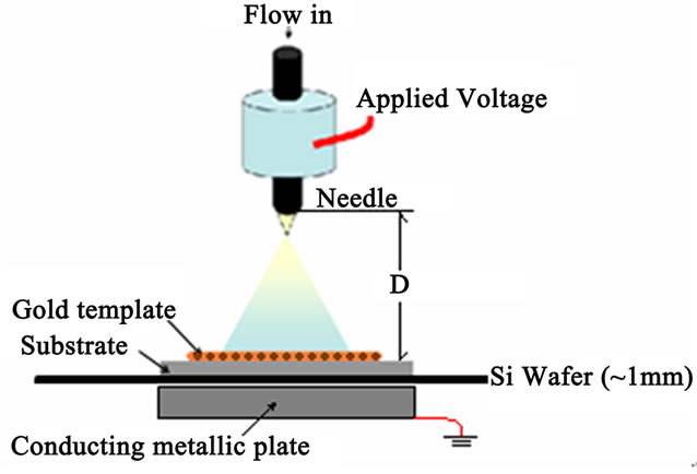 (b)
(b)
Figure 1. (a) Schematic diagram of the electrospraying setup with nozzle designs; and (b) Schematic illustration of the equipment set-up used for TAEA patterning process.
titanium was used as substrate. The nozzle tip-substrate distance and the liquid flow rate were controlled at 40 mm and 10 μl/min. A copper TEM grid and 3 wt% HA suspension were used as the template and the liquid. The spraying time was set at 10 minutes. The patterns prepared were examined and measured using the optical microscope and the scanning electron microscope (FE-SEM, JEOL JSM/6310F).
3. RESULTS & DISCUSSION
3.1. Electrohydrodynamic Atomization Phenomenon at the Nozzle Tip
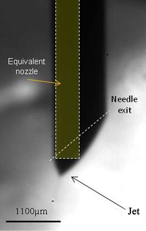
It is well-known that the flow liquid could form a conical shape meniscus when the electric driving force is controlled at specific range. Using a conventional nozzle with the tip angle of 90˚, the liquid cone formed symmetrically near the centre of the nozzle orifice (Figure 2(e)). However, it was observed an entirely different scenario while a nozzle with tilted outlet was used. As shown in Figures 2(a)-(d), the liquid cone and jet locate near the sharp tip rather than in the centre of the nozzle orifice. It was also observed that the diameter of the liquid cone dramatically reduced compared with the liquid cone formed when using the nozzle with 90˚ tip angle. This phenomenon demonstrates that the electric field, which drives the liquid to form the cone shape meniscus, may not be symmetry, and an electric field concentration may occur at the sharp tip of the tilted nozzle.
The relationship between the nozzle tip radius and the electric field was investigated by Jones and Thong in 1979 [24]. It was assumed that, irrespective of geometrical
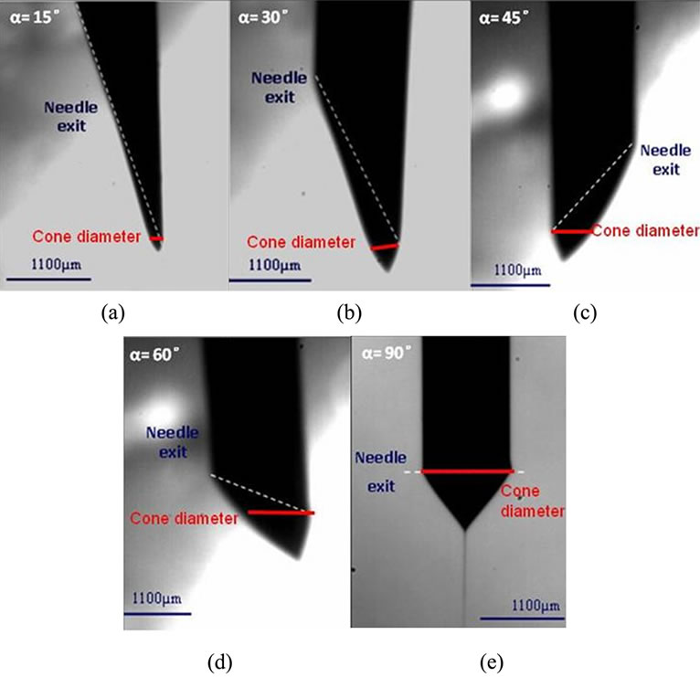
Figure 2. High speed camera images of liquid jets achieved using the nozzles with different tip angle.
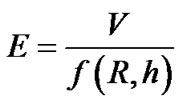
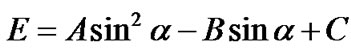
considerations, the same field conditions are required for the onset of the cone-jet mode. The electrical potential V will be related to the electrical field E generated in the liquid surface situated at the capillary edge, by
 (1)
(1)
where f(R, h) is a geometrical function of the nozzle tip radius, R, and the nozzle tip-grounded plane distance, h. An accepted approximation [12] for this function is given in Eq.2.
 (2)
(2)
where A is an empirical constant ranging from 0.5 to 0.707. Variation of the f(R, h) value with respect to changes in R can be obtained from
 (3)
(3)
when  during jetting,
 . This means that while the nozzle tip radius reduces, the f(R, h) value will reduce, and the electric field at the nozzle tip will increase accordingly when the same electrical potential is applied.
This relationship was investigated based on an assumption that the nozzles used are of the regular shape, that the tip angle is 90˚. It seems to be not applicable in our case. However, if taking an in-sight analysis of the cone-jet mode formed using the tilted nozzles, a linkage between the nozzle tip angle and an equivalent nozzle orifice radius could be observed.
As shown in Figure 2, high speed camera images clearly indicate the changes in the jetting towards a grounded plate. The diameter of the liquid conical meniscus, highlighted in red, formed under the varied nozzles was found to increase significantly with the increase of the tip angle. Cones of the minimum and maximum diameter appear while the 15˚ and 90˚ nozzle were used. To study and compare the electric field distribution at the nozzle tip, an equivalent nozzle of 90˚ tip angle, as highlighted in yellow in Figure 3(a), is assigned to all the nozzles. The relationship between the equivalent nozzle diameter and the nozzle tip angle was investigated. As shown in Figure 3(b), the relationship follows
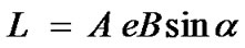 (4)
(4)
where A and B are 83 and 7, respectively. L is the equivalent nozzle diameter and α is the nozzle tip angle. Clearly, according to Eq.4, the equivalent nozzle diameter of the titled nozzle decreases with the tip angle, which means L15˚ < L30˚ < L45˚ < L60˚ < L90˚. Due to the relationship of the conventional nozzle radius and the electric field as afore-introduced, the electric field at each nozzle tip can be compared as shown in Figure 3(c). The relationship between the electric field and nozzle tip angle is given by:
 (5)
(5)
where A, B and C are 7, 14 and 8, respectively. Therefore, the electric field concentration occurs at the sharp nozzle tip. The relationship of the electric field near the nozzle tip follows E15˚ > E30˚ > E45˚ > E60˚ > E90˚.
3.2. The Influence of Nozzle Tip Angle to the Stability of Cone-Jet Mode
When using a 3% wt HA suspension as the liquid for electrospraying, the relationship between applied voltage and flow rate is shown in Figure 4. The cone-jet mode can only be achieved when the flow rate and the applied voltage are in a distinctive domain. The maximal liquid flow rates for achieving a stable cone-jet mode using the nozzle of 15˚, 30˚, 45˚, 60˚ tip angles exhibit much higher than that of 90˚ nozzle. The nozzle with 45˚ tip angle shows the highest flow rate up-limit which is approximately 68 μl/min. It is almost double of the maximal flow rate while using the nozzle with 90˚ tip angle. The voltage range (ΔV between maximal and minimal applied voltage) at a specific flow rate was also found to decrease with the decrease of the nozzle tip angle. To confirm this finding, pure ethanol, which is a conventional liquid for electrospraying research, was also used. The similar scenario was observed. The highest flow rate up-limit for stable cone-jet mode was also found while using the nozzle of 45˚ angle. The difference of flow rate up-limit between the highest and the lowest was found to be further enlarged.
3.3. The Influence of Nozzle Tip Angle to the Ha Relic Size Distribution
The relic size distribution diagrams were built using 3% wt HA suspension (Figure 5). It was found that the main relic size dramatically decreased with the decreasing nozzle tip angle. The main size of the HA relics deposited varied between 2 to 3 μm using the nozzle of 15˚ tip angle, which was nearly half of the main relic size range when the nozzle with 90˚ tip angle was used. This phenomenon is mainly due to the electric field concentration as demonstrated. As the same flow rate was set during the HA relics collection, more electric charge presented at the liquid cone formed at the sharper nozzle tip. Subsequently, the liquid cone formed a jet and then broken up into droplets. Higher electric charge presented in the surface of the droplets, emitted from the cone-jet mode with a nozzle of smaller tip angle. Such phenomenon enhanced the possibility that the highly charged droplet to reach the Reileigh charge limit [11], as showed in the following formula.
 (a)
(a)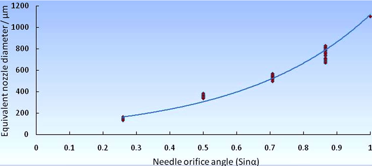 (b)
(b)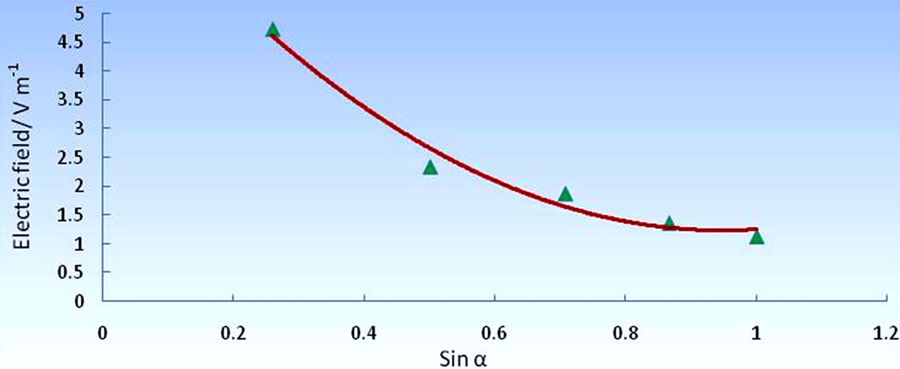 (c)
(c)
Figure 3. (a) Schematic illustration of the concept of equivalent nozzle when using a titled nozzle; (b) The relationship between the equivalent nozzle diameter and orifice angle; and (c) The relationship between electric field and nozzle tip angle.
.
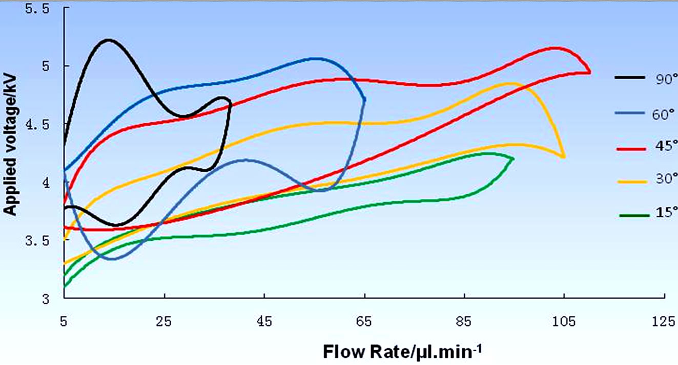
Figure 4. Relationship between applied voltage and flow rate for achieving stable jetting when using different nozzles.
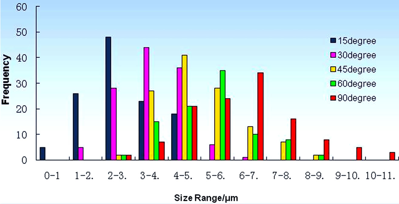
Figure 5. The as-deposited HA relic size distribution by electrospraying with different nozzles.
where  is the Rayleigh charge limit (C),
  is the surface tension, ε0 is the vacuum dielectric constant and rd is the droplet radius (m).
When the charge on a single droplet reaches the limit, droplet breaks up into two or more smaller droplets by the over-limited charge. Therefore, when using the nozzle with 15˚ tip angle, the droplet fission occurred, and smaller liquid droplets were therefore formed.
3.4. Ha Patterning Process with Refined Taea Setup
Template-assisted electrohydrodynamic atomization spraying (TAEA) was previously developed to create bioceramic patterns to up-regulate the bone cell behavior [23]. To improve the resolution (the minimal diameter of the pattern) of TAEA, the droplets with reduced dimensions are compulsory. Based on the findings above, the nozzle with 15˚ tip angle was chosen for HA patterning trials. As shown in Figures 6(a) and (b), the HA line pattern of < 10 μm in width and the fine square HA patterns of the width below 10 μm were successfully achieved. This is nearly one tenth in diameter of the patterns reported previously. The resolution of TAEA was dramatically improved, as expected. In addition, the inset micrograph of Figure 5 clearly confirms that dense surface topography assembled by the HA nanocrystals, which favors the cellular attachment.
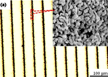
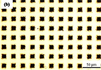
Figure 6. HA patterns of (a) line shape and (b) square shape prepared using TAEA spraying with the nozzle of 15˚ tip angle. The inset shows the high magnification micrograph of the partial HA patterns.
4. CONCLUSION
The study showed that the flow rate up-limit for the stable cone-jet electrospraying mode was significantly increased while reducing the nozzle tip angle. The HA relic size distribution were found to dramatically decrease with the decreased tip angle. Based on these findings, the resolution of TAEA patterning process was further increased within 10 μm. This investigation can be utilized to improve biomaterials properties to a desired level to suit more advanced applications without causing cumbersome operational drawbacks. Furthermore, this generic theory can suggest new strategies for processing advanced nanostructured materials for biomedical applications.
5. ACKNOWLEDGEMENTS
The authors would like to thank the National Nature Science Foundation of China (Grant No. 51103128) and Fundamental Research Funds for the Central Universities (Grant No. 2011QNA4004) for the financial support which enabled this work.
REFERENCES
- Whitesides, G.M. (2003) The “right” size in nanobiotechnology. Nature Biotechnology, 21, 1161-1165. doi:10.1038/nbt872
- Sarikaya, M., Tamerler, C., Jen, A.K.Y., Schulten, K. and Baneyx, F. (2003) Molecular biomimetics: Nanotechnology through biology. Nature Materials, 2, 577-585. doi:10.1038/nmat964
- Lewis, J.A. (2006) Direct ink writing of 3D functional materials. Advanced Functional Materials, 16, 2193-2204. doi:10.1002/adfm.200600434
- Park, J.U., Hardy, M., Kang, S.J., Barton, K., Adair, K., Mukhopadhyay, D.K., Lee, C.Y., Strano, M.S., Alleyne, A.G., Georgiadis, J.G., Ferreira, P.M. and Rogers, J.A. (2007) High-resolution electrohydrodynamic jet printing. Nature Materials, 6, 782-789. doi:10.1038/nmat1974
- Zeleny, J. (1914) The electrical discharge from liquids points and a hydrostatic method of measuring the electric intensities at their surfaces. Physics Review E, 3, 69-91. doi:10.1103/PhysRev.3.69
- Taylor, G. (1964) Disintegration of water drops in electric field. Proceedings of the Royal Society of London Series A—Mathematical and Physical Sciences, 280, 383-397. doi:10.1098/rspa.1964.0151
- Hartman, R.P.A., Brunner, D.J., Camelot, D.M.A., Marjnissen, J.C.M. and Scarlett, B. (1999) Electrohydrodynamic atomization in the conejet mode physical modeling of the liquid cone and jet. Journal of Aerosol Science, 30, 823-849. doi:10.1016/S0021-8502(99)00033-6
- Cloupeau, M. and Prunet-Foch, B. (1990) Eletrostatic spraying of liquids: Mainfunctioning modes. Journal of Electrostatic, 25, 165-184. doi:10.1016/0304-3886(90)90025-Q
- Rulison, A.J. and Flagan, R.C. (1994) Electrospray atomization of electrolytic solution. Journal of Colloid and Interface Science, 167, 135-145. doi:10.1006/jcis.1994.1341
- Funada, T. and Joseph, D.D. (2002) Viscous potential flow analysis of capillary instability. International Journal of Multiphase Flow, 28, 1459-1478. doi:10.1016/S0301-9322(02)00035-6
- Ganan-Calvo, A., Lasheras, J.C., Davila, J. and Barrero, A. (1994) The electrostatic spray emitted from an electrified conical meniscus. Journal of Aerosol Science, 25, 1121-1142. doi:10.1016/0021-8502(94)90205-4
- Hartman, R.P.A., Borra, J.P., Brunner, D.J., Marijnissen, J.C.M. and Scarlett, B. (1999) The evolution of electrohydrodynamic sprays produced in the cone-jet mode, a physical model. Journal of Electrostatics, 47, 143-170. doi:10.1016/S0304-3886(99)00034-0
- Ganan-Calvo, A., Davila, J. and Barrero, A. (1997) Current and droplet size in the electrospraying of liquids. Scaling laws. Journal of Aerosol Science, 28, 249-275. doi:10.1016/S0021-8502(96)00433-8
- Wilhelm, O., Madler, L. and Pratsinis, S.E. (2003) Electrospray evaporation and deposition. Journal of Aerosol Science, 34, 815-836. doi:10.1016/S0021-8502(03)00034-X
- Rayleigh, F.R.S. (1878) On the instability of jets. Proceedings London Mathematical Society, 10, 4-13. doi:10.1112/plms/s1-10.1.4
- Fenn, J.B., Mann, M., Meng, C.K. and Wong, S.F. (1989) Electrospray ionization for mass spectrometry of large biomolecules. Science, 246, 64-71. doi:10.1126/science.2675315
- Vanzomeren, A.A., Kelder, E.M., Marijnissen, J.C.M. and Schoonman, J. (1994) The production of thin-films of LiMn2O4 by electrospraying. Journal of Aerosol Science, 25, 1229-1235. doi:10.1016/0021-8502(94)90211-9
- Lu, J., Chu, J., Huang, W. and Ping, Z. (2002) Preparation of thick Pb(Zr, Ti)O3 (PZT) film by electrostatic spray deposition (ESD) for application in micro-system technology. Japanese Journal of Applied Physics, 41, 4317- 4320. doi:10.1143/JJAP.41.4317
- Chen, C.H., Emond, M.H.J., Kelder, E.M., Meester, B. and Schoonman, J. (1999) Electrostatic sol-spray deposition of nanostructured ceramic thin films. Journal of Aerosol Science, 30, 959-967. doi:10.1016/S0021-8502(98)00075-5
- Hench, L.L. (1998) Bioceramics. Journal of American Ceramic Society, 81, 1705-1728. doi:10.1111/j.1151-2916.1998.tb02540.x
- Li, X., Huang, J., Ahmad, Z. and Edirisinghe, M.J. (2007) Electrohydrodynamic coating of metal with nano-sized hydroxyapatite. Journal of Biomedical Materials and Engineering, 17, 335-346.
- Ahmad, Z., Huang, J., Edirisinghe, M.J., Jayasinghe, S.N., Best, S.M., Bonfield, W., Brooks, R.A. and Rushton, N. (2006) Electrohydrodynamic print-patterning of nanohydroxyapatite. Journal of Biomedical Nanotechnology, 2, 201-207. doi:10.1166/jbn.2006.032
- Li, X., Koller, G., Huang, J., Di Silvio, L., Renton, T., Esat, M., Bonfield, W. and Edirisinghe, M. (2010) A Novel Jet-based nHA patterning technique for osteoblast guidance. Journal of the Royal Society Interface, 7, 189-197. doi:10.1098/rsif.2009.0101
- Jones, A.R. and Thong, K.C. (1971) The production of charged monodisperse fuel droplets by electrical dispersion. Journal of Physics D, 4, 1159-1166. doi:10.1088/0022-3727/4/8/316