International Journal of Clinical Medicine
Vol.4 No.7A1(2013), Article ID:34049,10 pages DOI:10.4236/ijcm.2013.47A1002
The Endplate Morphology Changes with Change in Biomechanical Environment Following Discectomy

Engineering Center for Orthopaedic Research Excellence (E-CORE), Departments of Bioengineering and Orthopaedic Surgery, Colleges of Engineering and Medicine, University of Toledo, Toledo, USA.
Email: Vijay.Goel@utoledo.edu
Copyright © 2013 Aakash Agarwal et al. This is an open access article distributed under the Creative Commons Attribution License, which permits unrestricted use, distribution, and reproduction in any medium, provided the original work is properly cited.
Received April 10th, 2013; revised May 3rd, 2013; accepted May 13th, 2013
Keywords: Bone Remodeling; Spine Biomechanics; Disc Herniation; Discectomy; Endplates; Finite Element Study
ABSTRACT
Bone is a dynamic structure and is known to respond to changes in the load over time, in accordance with Wolff’s law. It states that the bone changes its shape and internal architecture in response to stresses acting on it [1]. Therefore, any structural changes in the spine may lead to bone remodeling due to changes in the optimal stress pattern. The changes in apparent density and thickness of the endplates following discectomy of varying amounts were analyzed. The study design coupled a bone remodeling algorithm based on strain energy density theory of adaptive remodeling with an experimentally validated 3D ligamentous finite element model of the spine. The apparent density and thickness of the index level endplates decreased above and below the region of discectomy. On the other hand, these parameters showed increases at the remaining regions of the endplate. There were no correlations between the amount of nucleus removed and the average percentage changes in apparent density and thickness of endplate above and below the discectomy region. However, the average percentage changes in apparent density and thickness at endplate in the other region increased with increase in amount of nucleus removed. These predictions are in agreement with the clinical observations [2-6].
1. Introduction
The vertebral endplate is a thin layer of dense subchondral bone which forms an interface between the intervertebral disc and the cancellous bone within the vertebral body [7]. The vertebral endplate transmits load to the adjoining intervertebral disc. It also acts as a semi permeable membrane for the transport of nutrients and waste between the vertebral body and intervertebral disc [8].
The material property and bone density of the endplate show regional variations. The posterolateral regions are significantly stiffer and stronger that the middle regions [9,10]. Along with variation in material properties, studies have also shown that the endplate’s thickness is not uniform, especially in the lumbar region. Roberts et al. found that the thickness of the subchondral vertebral bone is proportional to the amount of proteoglycan content of the adjacent disc [6]. These studies supports the theory that endplate responds to the hydrostatic pressure and undergoes remodeling. These changes in endplate morphology due to structural changes in the disc are critical because of the accompanying alterations in the nutrient permeability of the endplates. This process may initiate a vicious cycle of degeneration.
Malinin et al. studied the changes in the vertebral body adjacent to the acutely narrowed intervertebral disc in a baboon model [2]. They suggested that these changes were in response to changes in physical stress environment. Common clinical manifestations of a herniated disc are Modic changes. Modic changes are pathological changes in the vertebra of the spine. Modic et al. had first observed these changes and grouped them into three types based on different weighted signal intensity on MRI. Histological findings have also concurred with these changes in signal intensity on MRI [3]. Histological examination of Modic type 1 shows disruption and fissuring of the endplate and vascularized fibrous tissues within the adjacent marrow. Histological examination of Modic type 2 shows endplate disruption with yellow marrow replacement in the adjacent vertebral body. Modic type 3 is rare, and it is bone scar tissue. Histological examination shows dense woven bone; hence, no marrow to produce MRI signal. Another common manifestation observed after morphological changes in the endplate are lesions like Schmorl’s nodes [4].
In past, various groups have studied bone remodeling of different regions of spine [11-15]. However, to our knowledge there are no studies that have looked into remodeling of the endplates following discectomy. To gain insight into the changes in the endplate morphology with changes in the intervertebral disc, the adaptive bone remodeling algorithm was incorporated into ligamentous finite element model of the spine. The effects of changes in biomechanical environment, due to discectomy, on the thickness and apparent density distribution of the endplates at the index level were investigated. We hypothesize that the apparent density and thickness of endplate region next to discectomy (above and below the discectomy region) will decrease after discectomy due to decrease in load transfer. We also hypothesize that the apparent density and thickness of endplate at the regions adjacent to the discectomy region (residual region) will increase due to increase in load transfer.
2. Materials and Methods
2.1. The Finite Element Model
The finite element model used in this study is an experimentally validated 3D intact ligamentous lumbar spine (L3-L5) segment FE model. It was generated from reconstructed computer tomography scans of a cadaveric lumbar-spine specimen [16]. The FE model was experimentally validated using in vitro kinematic data, facet loads, ligament strains, and disc bulge under multiple load types [17-19]. In this FE model, the mesh density is 8-fold that of the previously remodeled spine mesh, as indictated by a convergence study [11]. The L3-L4 model consists of 24,070 elements, and 28,115 nodes and it is symmetric about the mid-sagittal plane [20]. The commercial software ABAQUS/StandardTM version 6.10 (Simulia, Inc. Rhode Island, USA) was used to construct and analyze the FE model. Table 1 summarizes the details of the FE model including components, element formulation, and material properties of elements [16].
2.2. The Remodeling Algorithm
The bone remodeling algorithm was incorporated into the FE model to predict the thickness and apparent density of the endplate in response to changes in the driving stimulus in an iterative manner [12]. The driving stimulus was the strain energy density, which has been extensively used in other computational remodeling studies [11,21]. The change in the material property was achieved by changing elastic modulus (correlated to apparent density)
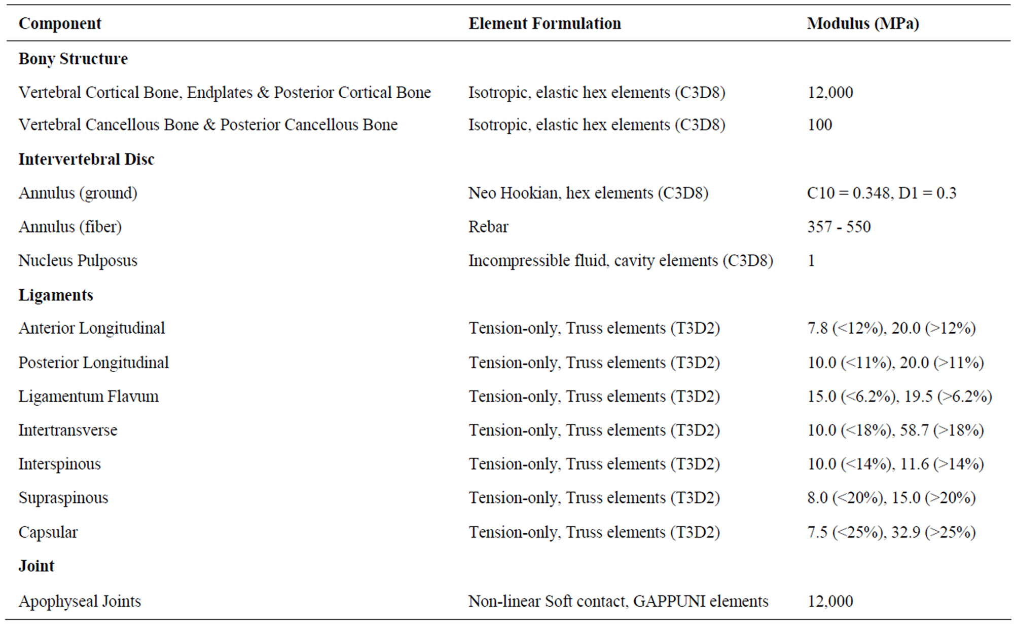
Table 1. The details of the FE model including components, element formulation, and material properties of elements.
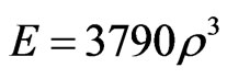
of the elements while the thickness was changed by moving the surface nodes of the endplates and vertebral cortex along their normal directions (and hence changing the shape). An established threshold (±35%) levels of stimulus was incorporated, within which the bone is unresponsive (lazy-zone), yielding neither change in material property nor shape (thickness) [22]. Furthermore, an upper (ρ = 1.74 g/cm³) and lower (ρ = 0.01 g/cm³) limits of element density were also assigned, beyond which no change in density was permitted [21,23,24]. The thickness also was assigned a lower limit of 0.05 mm. The remodeling criteria were executed until a convergence of the total strain energy of the model was observed. The apparent bone density was related to the elastic modulus (E) in FE model as follows [25]:
2.3. Optimization of Intact FE Model
The intact FE model was optimized for bone material properties (internal remodeling) in the entire bony region and, thickness (external remodeling) in endplates and vertebral cortex regions before discectomy was simulated.
For internal remodeling, the following equation was used, where  is the rate of change in elastic modulus of the element,
  is the internal remodeling rate constant,
  is the strain energy density of the element,
  is the average SED at time zero of all of the vertebral elements undergoing internal remodeling [26].
For external remodeling, the following equation was used, where  is the rate of surface growth perpendicular to the surface,
  is the external remodeling rate constant,
  is the strain energy density of the node,
  is the average SED at time zero of all the surface nodes undergoing external remodeling [26].

2.4. Modeling Discectomy in the Optimized FE Model
Discectomy was modeled based on the literature data to include annular defect and loss of nucleus as described below. The discectomy was simulated at the L4-L5 intervertebral disc of L3-L5 finite element model. The purpose was to investigate the changes in the endplate due to structural changes as a result of discectomy. A schematic of the discectomy model is shown in Figure 1. Annular defect was created in the posterolateral region of the L4-L5 intervertebral disc. The defect size was based on the average value reported in the literature, i.e. 45.6 mm2 [27]. The nucleus region closer to the defect was removed from the L4-L5 intervertebral disc. The average volume of nucleus removed in discectomy patients has been reported to be 2.0 cm3 (discectomy I) [27-29]. Additional models were simulated with 1) 4.0 cm3 (discectomy II) and 2) 8.0 cm3 (discectomy III) nucleus removal. This was undertaken to find the correlation between the amount of nucleus removed and the average change in density and thickness at the endplate.
2.5. Incorporating of Remodeling Algorithm in Discectomy FE Model
The remodeling equations used for the discectomy model were a little different from the intact FE model described above. In this case, each element had a specific optimized homeostatic strain energy density that was obtained as a result of optimization of the intact model. Therefore, for external remodeling, the stimulus for remodeling was governed by the difference between the strain energy density of the surface node of the discectomy model, and the optimized homeostatic strain energy density. Similarly for internal modeling the stimulus was the difference between the strain energy density of the element of the discectomy model, and the optimized homeostatic strain energy density.
Figure 1. Cross-section cut through L4-L5 intervertebral disc showing the schematic of the discectomy in the FE model. It gives a schematic of the intact and dissected models. Intact shows L4-L5 disc with complete central nucleus and annulus fibrosus. Dissected I shows that the left posterolateral aspect of annulus fibrosus and nucleus pulposus has been removed; Dissected II shows that the posterior region of nucleus pulposus and left posterolateral region of annulus fibrosus has been removed; Dissected III shows complete removal of nucleus pulposus and just left posterolateral region of annulus fibrosus.
2.6. Loading and Boundary Conditions
The loading criteria for optimization of the intact model consisted of compression of 400N coupled with flexion and extension. Pure compression was used for the discectomy models. The loading was applied to the superior surface of the L3 vertebra. The bottom of the L5 vertebra was completely constrained in all degrees of freedom. The density at each element was recorded at their centroid (which was obtained by averaging all of the values of the integration point inside the element). These values along with the spatial coordinate of the centroid were imported into MatlabTM. Then by using a custom made MatlabTM script, we made a contour plot of the density distribution in the endplate. The thickness of the endplate was calculated by using the thickness of the element at each nodal edge. Likewise, these were post-processed using a custom made MatlabTM script for preparation of thickness contour plots of the entire endplate. The normal compressive stress at each element was recorded at their centroid. It was then averaged from all constituent elements to obtain an average normal compressive stress of a region of interest.
3. Results
For clarity the results are sub grouped in to two categories based on the region of endplate:
1) Endplate regions below and above the discectomy region: Region of the endplates directly above and below the dissected nucleus pulposus and annulus fibrosus, and 2) Residual endplate region: Region of the endplates adjacent to the discectomy region.
Figures 2 and 3 show the density plot of L4 and L5 endplates respectively, after discectomy. Figures 4 and 5 show the thickness plot of L4 and L5 endplates respecttively, following discectomy. Figure 5 shows the stress vector distribution at L4 and L5 endplate region following discectomy with 400N of pure compression.
3.1. Endplate Regions below and above the Discectomy Region
Case I: Discectomy I The average density of L4 endplate at the region above the discectomy decreased by 50.4% compared to intact (Table 2). The average density of L5 endplate at the region below the discectomy decreased by 58.9% compared to intact (Table 3). The average thickness of L4 endplate at the region above the discectomy decreased by 15.1% compared to intact (Table 2). The average thickness of L5 endplate at the region below the discectomy decreased by 14.1% compared to intact (Table 3). The normal compressive stress on L4 endplate at the region above the discectomy decreased by 0.57 MPa compared
Figure 2. Apparent density (g/cm3) contour of L4 endplate (inferior) after Discectomy I. The average apparent density has decreased at the posterolateral region of endplate just above the dissected region. The average thickness has increased at the region adjacent to discectomy region.
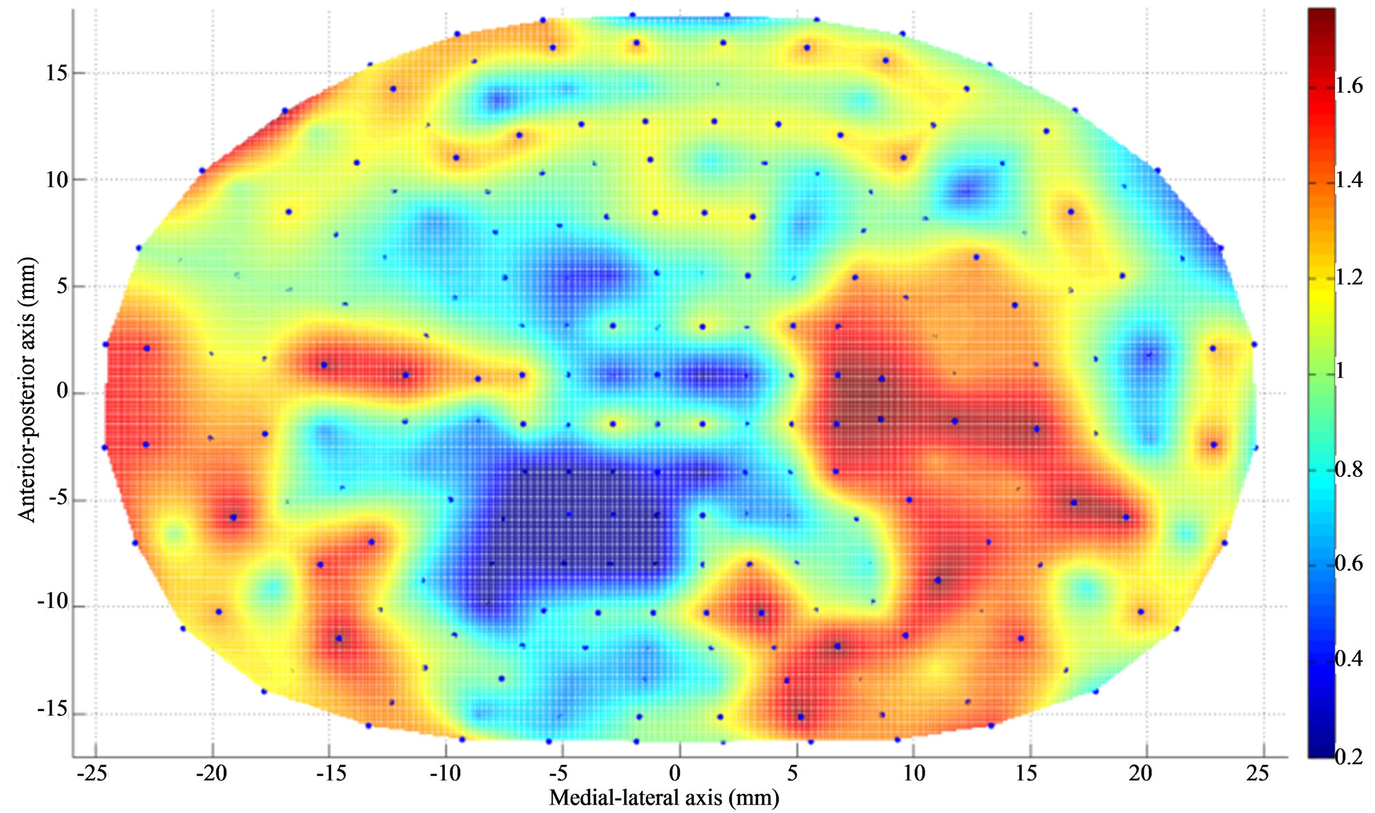
Figure 3. Apparent density contour (g/cm3) of L5 endplate (superior) after Discectomy I. The average apparent density has decreased at the posterolateral region of the endplate just below the dissected region. The average apparent density has increased at the region adjacent to discectomy region.
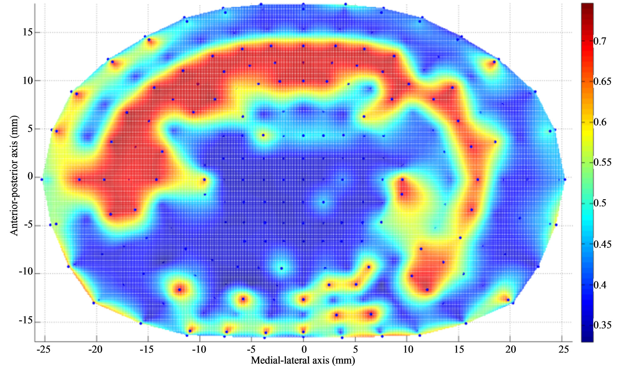
Figure 4. Thickness (mm) contour of L4 endplate (inferior) after Discectomy I. The average endplate thickness has decreased at the posterolateral region of the endplate just above the dissected region. The average thickness has increased at the region adjacent to discectomy region.
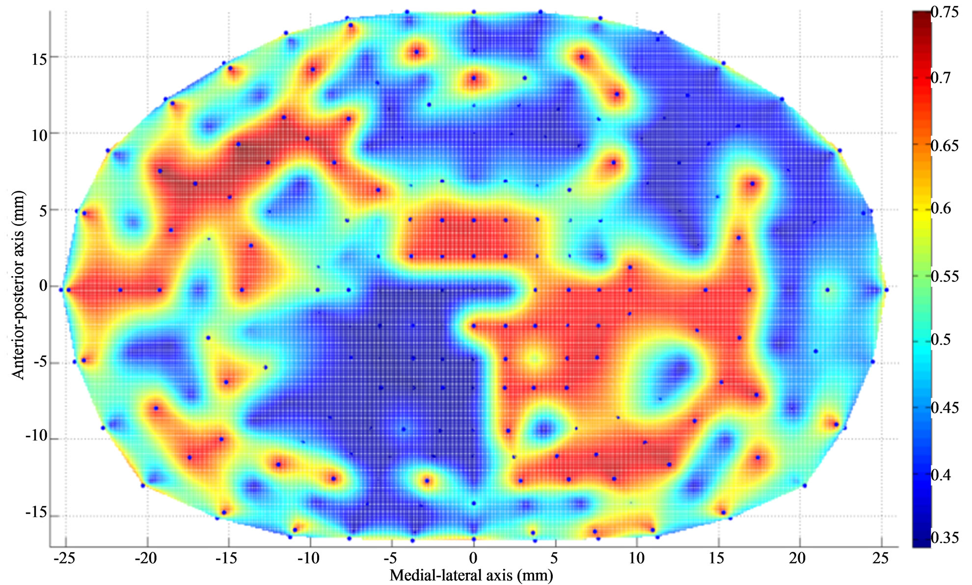
Figure 5. Thickness (mm) contour of L5 endplate (superior) after Discectomy I. The average endplate thickness has decreased at the posterolateral region of the endplate just below the dissected region. The average thickness has increased at the region adjacent to discectomy region.
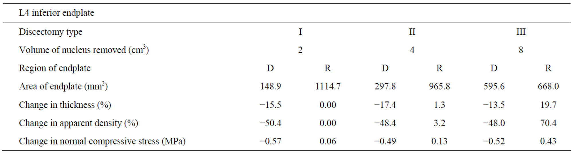
Table 2. Changes in thickness, apparent density and normal compressive stress at L4 inferior endplate (with respect to intact) with increasing amount of nucleus removal at 400N of follower load—D (dissected), R (residual).
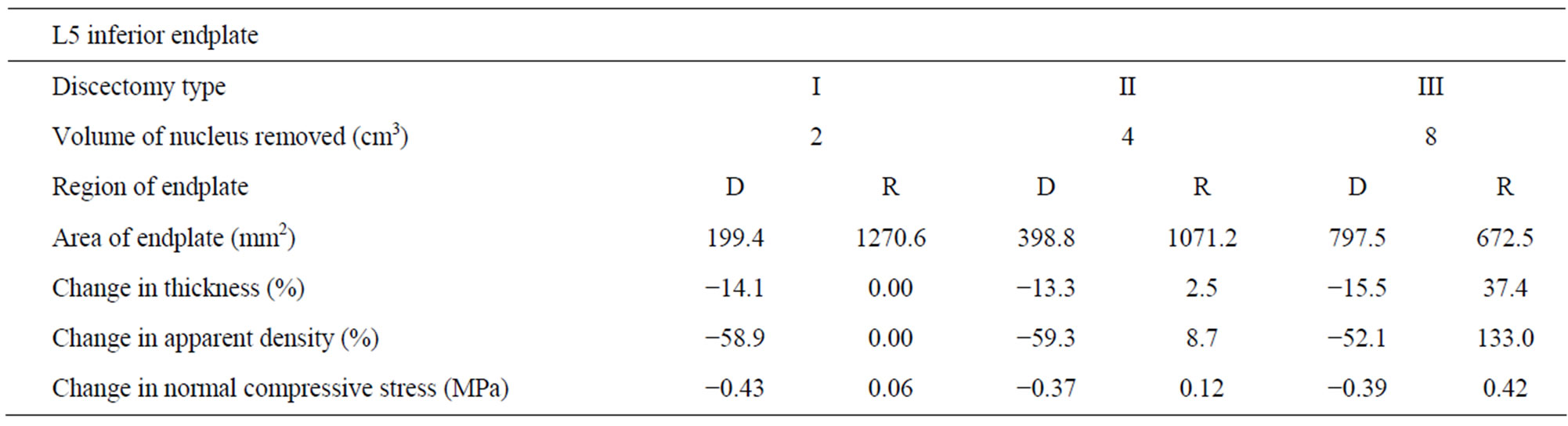
Table 3. Changes in thickness, apparent density and normal compressive stress at L5 superior endplate (with respect to intact) with increasing amount of nucleus removal at 400N of follower load—D (dissected), R (residual).
to intact (Table 2). The normal compressive stress on L5 endplate at the region below the discectomy decreased by 0.43 MPa compared to intact (Table 3).
Case II: Discectomy II The average density of L4 endplate at the region above the discectomy decreased by 48.4% compared to intact (Table 2). The average density of L5 endplate at the region below the discectomy decreased by 59.3% compared to intact (Table 3). The average thickness of L4 endplate at the region above the discectomy decreased by 17.4% compared to intact (Table 2). The average thickness of L5 endplate at the region below the discectomy decreased by 13.3% compared to intact (Table 3). The normal compressive stress on L4 endplate at the region above the discectomy decreased by 0.49 MPa compared to intact (Table 2). The normal compressive stress on L5 endplate at the region below the discectomy decreased by 0.37 MPa compared to intact (Table 3).
Case III: Discectomy III The average density of L4 endplate at the region above the discectomy decreased by 48% compared to intact (Table 2). The average density of L5 endplate at the region below the discectomy decreased by 52.1% compared to intact (Table 3). The average thickness of L4 endplate at the region above the discectomy decreased by 13.5% compared to intact (Table 2). The average thickness of L5 endplate at the region below the discectomy decreased by 15.5% compared to intact (Table 3). The normal compressive stress on L4 endplate at the region above the discectomy decreased by 0.52 MPa compared to intact (Table 2). The normal compressive stress on L5 endplate at the region below the discectomy decreased by 0.39 MPa compared to intact (Table 3).
3.2. Residual Endplate Region
Case I: Discectomy I The average density and thickness of L4 endplate at the regions adjacent to the discectomy region didn’t change significantly compared to intact (Table 2). The average density and thickness of L5 endplate at the regions adjacent to the discectomy region didn’t change significantly compared to intact (Table 3). The normal compressive stress on L4 endplate at the regions adjacent to the discectomy region increased by 0.06 MPa compared to intact (Table 2). The normal compressive stress on L5 endplate at the regions adjacent to the discectomy region increased by 0.06 MPa compared to intact (Table 3).
Case II: Discectomy II The average density of L4 endplate at the regions adjacent to the discectomy region increased by 3.2% compared to intact (Table 2). The average density of L5 endplate at the regions adjacent to the discectomy region increased by 8.7% compared to intact (Table 3). The average thickness of L4 endplate at the regions adjacent to the discectomy region increased by 1.3% compared to intact (Table 2). The average thickness of L5 endplate at the regions adjacent to the discectomy region increased by 2.5% compared to intact (Table 3). The normal compressive stress on L4 at the regions adjacent to the discectomy region increased by 0.13 MPa compared to intact (Table 2). The normal compressive stress on L5 endplate at the regions adjacent to the discectomy region increased by 0.12 MPa compared to intact (Table 3).
Case III: Discectomy III The average density of L4 endplate at the regions adjacent to the discectomy region increased by 70.4% compared to intact (Table 2). The average density of L5 endplate at the regions adjacent to the discectomy region increased by 133.0% compared to intact (Table 3). The average thickness of L4 endplate at the regions adjacent to the discectomy region increased by 19.7% compared to intact (Table 2). The average thickness of L5 endplate at the regions adjacent to the discectomy region increased by 37.4% compared to intact (Table 3). The normal compressive stress on L4 endplate at the regions adjacent to the discectomy region increased by 0.43 MPa compared to intact (Table 2). The normal compressive stress on L5 endplate at the regions adjacent to the discectomy region increased by 0.42 MPa compared to intact (Table 3).
4. Discussion
The objective of this study was to predict the effect of changes in biomechanical environment, due to discectomy, on the thickness and apparent density distribution of the endplates at the index level. A finite element analysis along with bone remodeling algorithm was undertaken to achieve this objective.
The regional endplate thickness and apparent density changed after disc discectomy. This change in morphology is attributed to the Wolff’s law of bone remodeling. It is evident from the contours that the changes in the endplate thickness and apparent density show similar trends. These lower thickness and density may lead to endplate fracture in these regions due to their resultant inferior mechanical properties [30].
Contrary to decreases in apparent density and thickness in the regions above and below discectomy, increases in apparent density and thickness were observed at the regions adjacent to the discectomy region (residual regions). This was due to increase in normal compressive stress through these residual regions after discectomy, Figure 6. The normal compressive stress increased and hence did the apparent density and thickness, with increase in amount of nucleus removed. These increases in
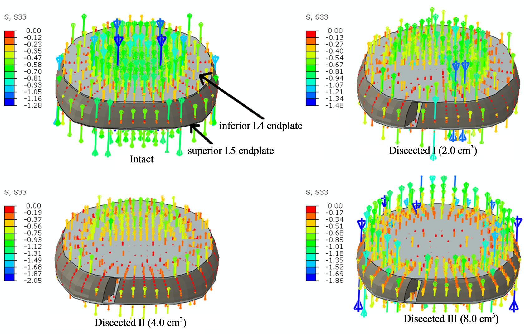
Figure 6. The figure shows the normal compressive stress distribution at L4 endplate region following discectomy with 400N of pure compression. Intact shows stresses being developed at all the regions of the endplate. Dissected I shows that the left posterolateral aspect of the endplate has no stresses due to discectomy below it; Dissected II shows that the posterior aspect of the endplate has no stresses due to discectomy below it; Dissected III shows that the central region of the endplate has no stresses due to discectomy of entire nucleus pulposus.
endplate thickness and apparent density are critical as it could in turn change the nutrient and waste permeability of the endplates that would affect the health of the intervertebral disc, starting a vicious cycle.
Another finding of our study was that the percentage decrease in apparent density and thickness at the endplate (above and below dissected region) region next to discectomy doesn’t show any correlation with the amount of nucleus removed. As shown in the results the normal compressive stress values decreased by similar values and hence the decrease in apparent density and thickness are similar, with increase in amount of nucleus removed.
Following discectomy, the load transfer through the intervertebral region changes and this in turn changes the strain energy density in the surrounding regions. The removal of a section of annulus fibrosus, and nucleus pulposus, increases the load transfer through the residual elements of the disc (Figure 6). This increase in load transfer through remaining regions of discs increases the strain energy density of the regions away from discectomy. Conversely, endplate regions next to discectomy will develop lower strain energy density. These changes in strain energy density result in the change of thickness and apparent density of the endplates as shown above. Clinical studies have also shown increases in bone mass adjacent to disc after changes in disc properties. For example, it has been shown in the literature that the trabecular bone mass adjacent to an incised disc increases by 50% in 2 years period (in a sheep) [5]. This is also in accordance to a previous study that observed higher endplate thickness at the regions of higher proteoglycan [6].
This study also has some limitations, like any other investigation. First, there are no muscle forces in our model but this limitation is mitigated by simulating effects of muscle forces in the form of a compression follower load. Patwardhan et al. [31], have shown that simulation of a follower load in cadaver studies provides similar kinematics response as in vivo. Second, our model simulates single geometry of the spine model and thus doesn’t account for variations in the patients/cadavers. Third, to simulate the bone remodeling we have used strain energy density stimulus from literature. Although an established empirical relation, but may not be the true biological stimulus. However this theory is well advocated and strain energy density is an interpretable physical scalar, which is related to both stress and strain [24]. Last but not the least, disc remodeling (or degeneration) was not simulated in this study and would be included in future studies.
5. Conclusion
This study provides insight about changes in the endplate morphology following discectomy. The results suggest that the apparent density and thickness of the index level endplates decrease above and below the region of discectomy, and increase at the remaining regions, as a compensatory mechanism. We didn’t find any correlation between the amount of nucleus removed and the average percentage changes in apparent density and thickness of endplates above and below the discectomy region. However, the average percentage changes in apparent density and thickness of endplate at the regions adjacent to the discectomy region increased with increase in amount of nucleus removed.
6. Acknowledgements
Work supported in part by a grant from Intrinsic Therapeutics (USA).
REFERENCES
- J. Wolf, “Julis Wolff and His Law of Bone Remodeling,” Der Orthopäde, Vol. 24, No. 5, 1995, p. 378.
- T. Malinin and M. D. Brown, “Changes in Vertebral Bodies Adjacent to Acutely Narrowed Intervertebral Discs: Observations in Baboons,” Spine (Phila Pa 1976), Vol. 32, No. 21, 2007, pp. E603-E607.
- T. Yasuma, et al., “Histological Changes in Aging Lumbar Intervertebral Discs. Their Role in Protrusions and Prolapses,” The Journal of Bone and Joint Surgery, Vol. 72, No. 2, 1990, pp. 220-229.
- D. Resnick and G. Niwayama, “Intravertebral Disk Herniations: Cartilaginous (Schmorl’s) Nodes,” Radiology, Vol. 126, No. 1, 1978, pp. 57-65.
- R. J. Moore, et al., “Remodeling of Vertebral Bone after Outer Anular Injury in Sheep,” Spine (Phila Pa 1976), Vol. 21, No. 8, 1996, pp. 936-940. doi:10.1097/00007632-199604150-00006
- S. Roberts, et al., “Does the Thickness of the Vertebral Subchondral Bone Reflect the Composition of the Intervertebral Disc?” European Spine Journal, Vol. 6, No. 6, 1997, pp. 385-389. doi:10.1007/BF01834064
- W. T. Edwards, et al., “Structural Features and Thickness of the Vertebral Cortex in the Thoracolumbar Spine,” Spine, Vol. 26, No. 2, 2001, pp. 218-225. doi:10.1097/00007632-200101150-00019
- S. Ferguson and T. Steffen, “Biomechanics of the Aging Spine,” European Spine Journal, Vol. 12, 2003, pp. 97- 103. doi:10.1007/s00586-003-0621-0
- J. P. Grant, T. R. Oxland and M. F. Dvorak, “Mapping the Structural Properties of the Lumbosacral Vertebral Endplates,” Spine, Vol. 26, No. 8, 2001, pp. 889-896. doi:10.1097/00007632-200104150-00012
- T. G. Lowe, et al., “A Biomechanical Study of Regional Endplate Strength and Cage Morphology as It Relates to Structural Interbody Support,” Spine, Vol. 29, No. 21, 2004, pp. 2389-2394. doi:10.1097/00007632-200104150-00012
- V. K. Goel, et al., “Cancellous Bone Young’s Modulus Variation within the Vertebral Body of a Ligamentous Lumbar Spine—Application of Bone Adaptive Remodeling Concepts,” Journal of Biomechanical Engineering, Vol. 117, No. 3, 1995, pp. 266-271. doi:10.1115/1.2794180
- N. M. Grosland and V. K. Goel, “Vertebral Endplate Morphology Follows Bone Remodeling Principles,” Spine (Phila Pa 1976), Vol. 32, No. 23, 2007, pp. E667- E673.
- J. Homminga, et al., “Can Vertebral Density Changes Be Explained by Intervertebral Disc Degeneration?” Medical Engineering & Physics, Vol. 34, No. 4, 2012, pp. 453- 458. doi:10.1016/j.medengphy.2011.08.003
- J. D. Jovanović and M. L. Jovanović, “Biomechanical Model of Vertebra Based on Bone Remodeling,” Medicine and Biology, Vol. 11, No. 1, 2004, pp. 35-39.
- F. M. Pfeiffer, D. L. Abernathie and D. E. Smith, “A Computational Approach to Bone Remodeling Postoperative to Facet Fusion,” ASME 2008 3rd Frontiers in Biomedical Devices Conference, Irvine, 18-20 June 2008, pp. 13, 14.
- S. Vadapalli, et al., “Biomechanical Rationale for Using Polyetheretherketone (PEEK) Spacers for Lumbar Interbody Fusion—A Finite Element Study,” Spine (Phila Pa 1976), Vol. 31, No. 26, 2006, pp. E992-E998.
- A. P. Dooris, et al., “Load-Sharing between Anterior and Posterior Elements in a Lumbar Motion Segment Implanted with an Artificial Disc,” Spine (Phila Pa 1976), Vol. 26, No. 6, 2001, pp. E122-E129.
- V. K. Goel, et al., “Anatomic Facet Replacement System (AFRS) Restoration of Lumbar Segment Mechanics to Intact: A Finite Element Study and in Vitro Cadaver Investigation,” SAS Journal, Vol. 1, No. 1, 2007, pp. 46-54. doi:10.1016/S1935-9810(07)70046-4
- V. K. Goel, et al., “Interlaminar Shear Stresses and Laminae Separation in a Disc. Finite Element Analysis of the L3-L4 Motion Segment Subjected to Axial Compressive Loads,” Spine (Phila Pa 1976), Vol. 20, No. 6, 1995, pp. 689-698. doi:10.1097/00007632-199503150-00010
- K. Sairyo, et al., “Athletes with Unilateral Spondylolysis Are at Risk of Stress Fracture at the Contralateral Pedicle and Pars Interarticularis—A Clinical and Biomechanical Study,” American Journal of Sports Medicine, Vol. 33, No. 4, 2005, pp. 583-590. doi:10.1177/0363546504269035
- H. Weinans, et al., “Adaptive Bone Remodeling around Bonded Noncemented Total Hip Arthroplasty: A Comparison between Animal Experiments and Computer Simulation,” Journal of Orthopaedic Research, Vol. 11, No. 4, 2005, pp. 500-513. doi:10.1002/jor.1100110405
- D. R. Carter, “Mechanical Loading Histories and Cortical Bone Remodeling,” Calcified Tissue International, Vol. 36, No. 1, 1984, pp. S19-S24. doi:10.1007/BF02406129
- W. T. Edwards, et al., “Structural Features and Thickness of the Vertebral Cortex in the Thoracolumbar Spine,” Spine (Phila Pa 1976), Vol. 26, No. 2, 2001, pp. 218-225.
- H. Weinans, R. Huiskes and H. Grootenboer, “The Behavior of Adaptive Bone-Remodeling Simulation Models,” Journal of Biomechanics, Vol. 25, No. 12, 1992, pp. 1425-1441. doi:10.1016/0021-9290(92)90056-7
- D. R. Carter and W. C. Hayes, “The Compressive Behavior of Bone as a Two-Phase Porous Structure,” The Journal of Bone and Joint Surgery, Vol. 59, No. 7, 1977, pp. 954-962.
- V. K. Goel, et al., “Cancellous Bone Young’s Modulus Variation within the Vertebral Body of a Ligamentous Lumbar Spine—Application of Bone Adaptive Remodeling Concepts,” Journal of Biomechanical Engineering, Vol. 117, No. 3, 1995, pp. 266-271. doi:10.1115/1.2794180
- M. J. McGirt, et al., “A Prospective Cohort Study of Close Interval Computed Tomography and Magnetic Resonance Imaging after Primary Lumbar Discectomy: Factors Associated with Recurrent Disc Herniation and Disc Height Loss,” Spine, Vol. 34, No. 19, 2009, pp. 2096- 2103. doi:10.1097/BRS.0b013e3181b34a9a
- K. N. Fountas, et al., “Correlation of the Amount of Disc Removed in a Lumbar Microdiscectomy with Long-Term Outcome,” Spine, Vol. 29, No. 22, 2004, pp. 2521-2524. doi:10.1097/01.brs.0000145413.79277.d0
- G. Schmid, et al., “Lumbar Disk Herniation: Correlation of Histologic Findings with Marrow Signal Intensity Changes in Vertebral Endplates at MR Imaging1,” Radiology, Vol. 231, No. 2, 2004, pp. 352-358. doi:10.1148/radiol.2312021708
- F.-D. Zhao, et al., “Vertebral Fractures Usually Affect the Cranial Endplate Because It Is Thinner and Supported by Less-Dense Trabecular Bone,” Bone, Vol. 44, No. 2, 2009, pp. 372-379. doi:10.1016/j.bone.2008.10.048
- A. G. Patwardhan, et al., “Effect of Compressive Follower Preload on the Flexion-Extension Response of the Human Lumbar Spine,” Journal of Orthopaedic Research, Vol. 21, No. 3, 2006, pp. 540-546. doi:10.1016/S0736-0266(02)00202-4