Open Journal of Civil Engineering
Vol.08 No.02(2018), Article ID:84476,19 pages
10.4236/ojce.2018.82009
Properties and Thermal Stress Analysis of Blended Cement Self-Compacting Concrete
Benson Kipkemboi1*, Shingo Miyazawa2
1Graduate School of Engineering, Ashikaga Institute of Technology, Ashikaga, Japan
2Department of Civil Engineering, Ashikaga Institute of Technology, Ashikaga, Japan

Copyright © 2018 by authors and Scientific Research Publishing Inc.
This work is licensed under the Creative Commons Attribution-NonCommercial International License (CC BY-NC 4.0).
http://creativecommons.org/licenses/by-nc/4.0/


Received: April 11, 2018; Accepted: May 11, 2018; Published: May 14, 2018
ABSTRACT
Self-Compacting concrete is a concrete that is able to flow and consolidate under its own weight, completely fill the formwork even in the presence of dense reinforcement, whilst maintaining homogeneity and without the need for any additional compaction. Self-Compacting concrete is achieved by using high proportions of powder content and super plasticizers. Due to this, pronounced thermal cracking is anticipated. Thermal cracking in concrete structures is of great concern. The objective of this research is to carry out experiments and investigate fresh and hardened properties of SCC developed using a blend of ordinary Portland cement and ground granulated blast furnace slag (GGBFS), to evaluate the applicability of Japan Concrete Institute (JCI) model equations and to find out any similarities and differences between Self-Compacting concrete and normal vibrated concrete―Portland blast furnace slag concrete class B. Thermal stress analysis of the proposed Self-Compacting concrete and normal vibrated concretes were investigated by simulation using 3D FEM analysis. To carry out these objectives, concrete properties such as autogenous shrinkage, adiabatic temperature rise, drying shrinkage, modulus of elasticity, splitting tensile strength and compressive strength were determined through experiments. From experimental results, it was observed that except for the fresh properties, the hardened properties of Self-Compacting exhibit similar characteristics to those of normal vibrated concrete at almost similar water to binder ratios. It was also established that Self-Compacting concrete at W/B of 32% with a 50% replacement of ground granulated blast furnace slag has better thermal cracking resistance than SCC with 30% GGBFS replacement. It is also found that provided the relevant constants are derived from experimental data, JCI model equations can be applied successfully to evaluate hardened properties of Self-Compacting concrete.
Keywords:
Self-Compacting Concrete, Blended Cement, Property Analysis, Thermal Stress Analysis

1. Introduction
The concept of Self-Compacting concrete was proposed by Professor Hajime Okamura of Kochi University of Technology, Japan, in 1986 as a solution to the growing durability concerns of concrete by the Japanese government. During his research, Okamura found that the main cause of the poor durability performances of Japanese concrete in structures was the inadequate consolidation of concrete during casting operations [1] . Self-Compacting concrete is a kind of a paradox concrete which requires that it must be highly flowable and yet it must not segregate during placement. Its development therefore must ensure a good balance between deformability and stability [2] . Due to this, Self-Compacting concrete therefore depends on the material characteristics, their mix proportions and the addition of superplasticizers and/or viscosity modifying agents. One of the most important material differences between Self-Compacting concrete and normal vibrated concrete is the incorporation of high amount of fines, low water binder ratio and superplasticizer usage to achieve its high deformability and stability [3] . It is important to note that the required high amount of fines (powder) has a direct influence on the cost. This can be mitigated by introducing supplementary cementitious materials as mineral admixtures. SCM are industrial by-products treated as wastes such as fly-ash, ground granulated blast furnace slag, silica fumes etc. Due to the abundance of silica content in them, they are used to acts as fillers in production of concrete with a general intention to cut on the cost. Their use also helps solve environmental CO2 emission problem by reducing on the usage of OPC which is the greatest direct global contributor in the construction sector. Mineral admixtures have the advantage that they help to improve particle packing and improve lubrication of aggregates, they decrease permeability and increase the workability and durability of concrete. It is also good to note that high amount of binder (cement) has a direct correlation with heat of cement hydration which is the reason of occurrence of many thermal cracks at early age in concrete. Thermal cracking in concrete structures is caused by volume change resulting from heat of cement hydration and autogenous shrinkage [4] . The main focus of this research is to produce powder type self-Compacting concrete using a blend of OPC and GGBFS. This will help reduce on the amount of OPC used as opposed to exclusive use of OPC alone. Ground granulated blast furnace slag used as a mineral admixture is an industrial waste. By using it in the production of SCC does not only reduce use of OPC but also come as a solution to industrial waste disposal challenges. GGBFS is also a supplementary cementitious material. Another objective of the research is to analyze thermal cracking resistance of the produced blended SCC so as to assess its suitability for use in mass concrete structures. Being a powder type SCC, large content of powder is used and thus a possibility of pronounced early age cracking due to the combined effect of heat of cement hydration and shrinkage. The hardened self-compacting concrete is dense, homogeneous and past research indicates that it has the same engineering properties and durability as normal vibrated concrete. Based on this finding, the other objective of this research is to evaluate the applicability of JCI model equations in analyzing hardened properties of SCC.
2. Materials and Mix Proportions
Materials used to carry out the study conformed to the quality and standard specifications of JSCE 2012 [5] and EFNARC [6] . Ground Granulated Blast furnace slag according to JIS A 6206:2013 [7] was used as an additive mineral admixture in both self-compacting concrete and normal vibrated concrete―Portland blast furnace slag concrete class B mix. Air entraining agent and polycarboxylicacid compound superplasticizer was also used to improve workability. Japanese method of mix proportioning was adopted in the design of SCC as stipulated in JSCE 2012 guideline [5] . Fine aggregate and coarse aggregate used to make concrete specimens were river sand and crushed hard sandstone respectively. The river sand used had Specific gravity of 2.59 g/cm3, % water absorption of 2.55% and fineness modulus of 2.83. Maximum size of coarse aggregates used was 20 mm with specific gravity of 2.64 g/cm3. Refer to Table 1 for the properties of the binder used.
Three types of SCC with GGBFS replacement ratios of 30%, 50% and 70% and a normal vibrated concrete―Portland blast furnace slag concrete class B with 50% replacement ratio of GGBFS were prepared. GGBFS with Blaine fineness of 3000cm2/g was used where the replacement ratio of blast furnace slag is low (30%) while GGBFS with fineness of 4000 cm2/g was used where the replacement ratio was 50% and 70%. This was in order to modify concrete workability and the 28 day compressive strength to be comparable with the proportions with high slag replacement ratio. The gypsum content quantities were also varied from one proportion to another in order to modify their strength development. This is because gypsum (SO3) controls the rate at which cement hardens. Table 2 and Table 3 show material mix proportions for self-compacting concrete and normal vibrated concrete―Portland blast furnace slag concrete class B respectively.

Table 1. Physical and chemical properties of binders used.
Table 2. Material mix proportions for self-compacting concrete.
Table 3. Material mix proportions for normal vibrated concrete―Portland blast furnace slag concrete class B.
3. Experiment Procedure
Trial mixing and tests were carried out to establish the appropriate proportions for self-compacting concrete. Standard tests for fresh properties of self-compacting concrete were carried out to verify self compactability as per JSCE recommendation and actual specimen sample was cast. For the measurement of temperature rise due to hydration heat of cement and autogenous shrinkage under semi-adiabatic condition, sample specimen was casted in a cubic mold with internal dimensions of 400 mm made of foamed polystyrene with 200 mm as its thickness on all concrete faces (see Figure 1 and Figure 2). Temperature rise was measured at the central portion of specimens and autogenous shrinkage of the specimen was also measured by using embedded strain gauge. For compressive strength test, modulus of elasticity and splitting tensile strength, cylindrical specimens of diameter 100 mm and depth 200 mm were made, cured under water at 20˚C and test measurements done at 3, 7, 28 and 91 days. For drying shrinkage test, 400 × 100 × 100 mm beam specimen was used. After demolding and the specimen cured under water at 20˚C for 7 days, the specimen was wiped dry and two contact cells paste centrally along the 400 mm length face at approximately 300 mm apart and 50 mm from the edge. The same was repeated on the opposite face. Two specimens were prepared for each sample. Drying shrinkage was measured at 0, 1, 7, 14, 28, 56, 91 and 180 days using the invar contact gauge. A numerical analysis of the test results was also carried out by 3-D FEM in order to evaluate thermal cracking resistance of the SCC concrete samples.
4. Results and Discussions
4.1. Fresh Properties of Concrete
Test results of the fresh properties of self-compacting concrete are shown in Figures 3-6. A series of trial mixes were carried out to establish appropriate
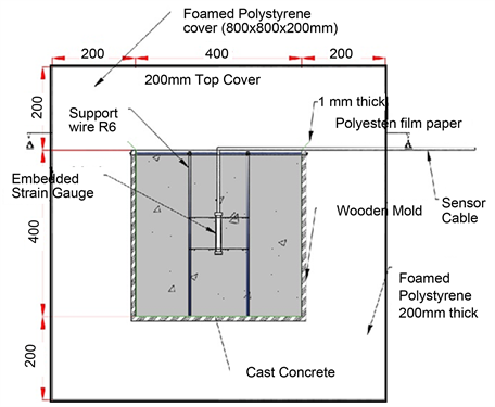
Figure 1. Shape and dimensions of section view of the 400 mm cubic mold.
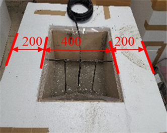
Figure 2. Casting of concrete sample in 400 mm cubic mold.
proportions for actual sample casting. Fresh properties of Self-Compacting concrete is a very important factor of consideration because it determines the ease with which concrete can be handled immediately after casting, during placing and finishing without any vibration. The main properties of self-compacting concrete that were tested include; slump flow test, V-funnel flow time test and U-Box test. From the results it is observed that most criteria set for assessing fresh properties according to JSCE 2012 guideline [5] and EFNARC [6] were satisfied for rank 2 mix proportion.

Figure 3. Slump flow test results of concrete samples.
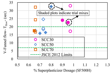
Figure 4. V-funnel test results for concrete samples.
4.2. Hardened Properties of Concrete
4.2.1. Compressive Strength and Strength Development of Concrete Samples
Figure 7 and Figure 8 show compressive strength and compressive strength development properties of self-compacting concrete and normal vibrated concrete―Portland blast furnace slag concrete class B. Compressive strengths at 3, 7, 28 and 91 days were experimentally obtained. Self-compacting concrete with 30% and 70% replacement ratio of GGBFS showed a high early age strength which reduced gradually after 7 days. Self-compacting concrete with 50%

Figure 5. Rank 2 U-Box filling height of SCC samples.
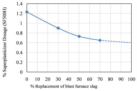
Figure 6. Relationship between superplasticizer dosage and % replacement of GGBFS
replacement ratio of GGBFS and normal vibrated concrete despite low early age strength exhibited a steady strength development to reach a high of 86.9 N/mm2 and 87.5 N/mm2 respectively at 91 days. This may be due to the variation in the SO3 content contained in the GGBFS samples.
Compressive strength development as depicted by the curves in Figure 8, were derived using JCI guideline 2016 [8] model Equation (1) and the experimental data.
(1)
where te is temperature adjusted age (days), tn is Strength control age of concrete
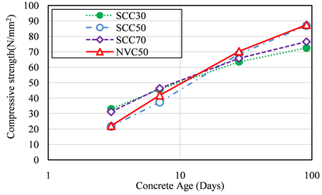
Figure 7. Compressive strength of concrete samples.
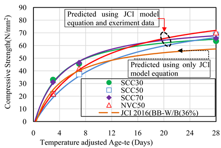
Figure 8. Compressive strength and predicted strength development of the concrete samples.
cured under water at 20˚C (day), Compressive strength of concrete at te (N/mm2), a, b are parameters that represent strength development, depending on type of cement and strength control age, is temperature adjusted age corresponding to initiation of hardening depending on the type of cement (days) and Compressive strength of concrete at tn (N/mm2). Temperature adjusted age (te) is calculated using Equation (2) of the JCI guideline 2016.
(2)
where is Period of constant temperature continuing in concrete (day); is concrete temperature for (˚C) and T0 is 1˚C. In the absence of experimental data, compressive strength of concrete at specified strength control age may be calculated as a factor of cement to water ratio (C/W) using Equation (3) of JCI guideline 2016.
(3)
where p1 and p2 are constants obtained from JCI guideline 2016 depending on the type of cement and the strength control age chosen i.e. 28, 56 or 91 days. The results in Figure 8 indicate that if the constants a and b are obtained from the experimental data, Equation (1) of the JCI guideline 2016 can be used to obtain strength development of both self-compacting concrete and normal vibrated concrete.
4.2.2. Splitting Tensile Strength of the Concrete Samples
Past research indicate that concrete’s mechanical behavior is governed by its compressive strength. Tensile strength of concrete is an important property that influences the safety, durability and service life of reinforced concrete. Studies on tensile strength of Self-Compacting concrete are limited and often do not agree [9] . According to Japan concrete institute guidelines 2016 [8] , the relationship between compressive strength and splitting tensile strength of normal concrete is obtained using Equation (4). This means that provided that we have compressive strength of concrete, Equation (4) can be used to calculate its splitting tensile strength.
(4)
where, is Splitting tensile strength of concrete at te (N/mm2), is Compressive strength of concrete at te (N/mm2), & are Constants.

Figure 9. Experimental results of splitting tensile strength of concrete samples.
According to JCI guidelines 2016 [8] , the constants C1 and C2 in Equation (4) shall be determined experimentally and if there is no experimental data, then they should be taken as 0.13 and 0.85 respectively. Results of the splitting tensile strength of the concrete samples tested are shown in Figure 9 and Figure 10.
From the results shown in Figure 9, splitting tensile strength seems to develop in a trend similar to that of the compressive strength development. The development is rapid at early ages and gradually reduces as concrete approaches strength control age. In this case, there is no significant difference in splitting tensile strength between self-compacting concrete and normal vibrated concrete. From Figure 10, it is observed that there exists slight disparity from the experimental and predicted splitting tensile/compressive strength relationship. Experimental relationship trend values are higher than predicted relationship trend values. From the relationship results in Figure 10, the constants C1 and C2 were established to be an average of 0.299 and 0.672 respectively for all the tested concrete samples. The similarity in both trends indicates that the proposed Japan concrete institute relationship function shown in Equation (4) can be used to analyze splitting tensile strength in self-compacting concrete to obtain satisfactory results.
4.2.3. Modulus of Elasticity of the Concrete Samples
Figure 11 shows the experimental results of the modulus of elasticity of self-compacting concrete and normal vibrated concrete. The values lies between 15 × 103 N/mm2 and 35 × 103 N/mm2 up to 28 day strength control age. Modulus of elasticity of concrete affects the maximum allowable stress and influences the
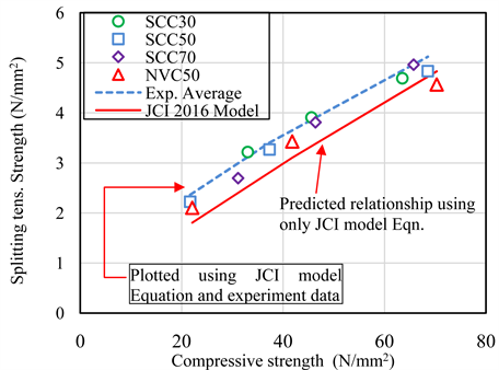
Figure 10. Relationship between splitting tensile and compressive strengths of concrete samples.
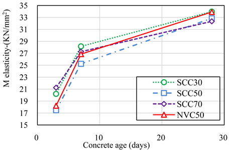
Figure 11. Experimental results of Modulus of elasticity of concrete samples.
rigidity of the design [10] . Figure 12 shows the predicted and experimental relationship between modulus of elasticity and compressive strength of the concrete samples. There is an observed similar relationship in both the experimental and predicted trends. Experimental modulus of elasticity of the concrete samples is lower compared to the predicted values.
JCI guideline 2016 [8] model Equation (5) was applied to predict the modulus of elasticity of the concrete samples.
(5)
where is Modulus of elasticity of concrete at te (N/mm2), is Compressive strength of concrete at te (N/mm2), are Constants. According to JCI guidelines 2016 [8] in the absence of experimental data, constants C3 and C4 in Equation (5) may be taken as 6300 and 0.45 respectively. From this study however, the constants C3 and C4 was established to be an average of 3524.3 and 0.533 respectively. This means that in the absence of modulus of elasticity experimental data, compressive strength data and JCI guideline 2016 [8] model equation can be used to calculate modulus of elasticity and satisfactory results obtained.
4.2.4. Heat of Cement Hydration of the Concrete Samples
Temperature increase in cast concrete is as a result of the heat evolved through the heat of cement hydration. This characteristic property is responsible for thermal cracking in concrete structures. Figure 13 shows the semi-adiabatic/ adiabatic temperature rise of the concrete samples. Adiabatic temperature rise was calculated from semi-adiabatic temperature rise data using the JCI guideline 2016 model Equation (6). Results shows that rate of adiabatic temperature rise in SCC30 is high compared to the other concrete mix proportions. This is due to

Figure 12. Relationship between modulus of elasticity and compressive strength of concrete samples.

Figure 13. Semi-adiabatic/adiabatic temperature rise of the concrete samples.
low replacement ratio of the blast furnace slag cement. The high replacement ratio of ordinary Portland cement means more tri-calcium aluminate (C3A) was available for rapid early age strength development [11] . SCC50 shows a high ultimate adiabatic temperature rise which is due to the large amount of binder content (546 kg/m3) available for the reaction as compared to the other samples.
(6)
where t is age in days, Q(t) the adiabatic temperature rise (˚C), the ultimate adiabatic temperature rise (˚C), parameters representing rate of adiabatic temperature rise and the age at starting of temperature rise.
4.2.5. Autogenous and Drying Shrinkage of the Concrete Samples
Autogenous shrinkage strain was measured at the center of the 400 mm cubic specimen alongside the semi-adiabatic temperature rise. Drying shrinkage was measured on specimens stored at a 20˚C ± 1˚C temperature and 60% ± 5% humidity conditions. This is important so as to accurately access the actual autogenous shrinkage in large member size mass concrete structures as well as the effects of drying shrinkage on exposed thin member sections. Figure 14 and Figure 15 shows autogenous shrinkage and drying shrinkage respectively of the concrete samples. Based on the two case scenarios of thick and thin members, the magnitude of drying shrinkage is large compared to autogenous shrinkage.
This indicates that self-compacting concrete undergoes high drying shrinkage which is due to large proportions of powder used to provide high flow-ability. SCC30 exhibits a lower autogenous shrinkage than SCC50, SCC70 and normal vibrated concrete. This indicates that the low specific surface area of blast

Figure 14. Autogenous shrinkage results of concrete samples under semi-adiabatic condition.

Figure 15. Drying shrinkage results of concrete samples.
furnace slag used as a mineral admixture was effective in reducing its autogenous shrinkage. SCC50 has the largest autogenous shrinkage. This is attributed to large amount of binder content. According to ASTM C157 “standard test method of length change of hardened hydraulic cement mortar and concrete” [12] , shrinkage of 500 micro-strain and lower is specified at 28 days of drying. In this results, at 28 days, all the samples conformed to the standard requirement. The variations in the magnitude of the autogenous and drying shrinkage is attributed to low water to binder ratio and variation in the unit amount of binder content used in each mix proportion.
5. Thermal Stress and Cracking Index Analysis by 3-D FEM Method
Temperature rise in concrete causes stress in the entire matrix. Stress increase with restraint boundary conditions in place, leads to early age crack development [8] . Depending on the intended use of the structure, cracks can be managed within acceptable limits. This is achieved by predicting the cracking probability by evaluating thermal cracking index which is a function of thermal cracking probability. See Equation (7).
(7)
where is thermal cracking probability and ICR is the thermal cracking index. Target probability depends on use of structure [13] . In order to predict early age thermal cracks in the concrete samples, the methodology described in JCI guideline 2016 was used. 3-D FEM analysis method quantitatively computes thermal stress and thermal cracking index by considering various conditions of the cast concrete such as structural dimensions, construction procedures, temperature histories, mechanical properties etc. [14] . Figure 16 shows the model mass structure that was used in this research. It consists of 1m thick concrete wall construction on a concrete slab. In order to input computational parameters for analysis, first initial temperature conditions of both the ground and concrete were set. Then the physical properties for both the ground and concrete were set. These includes; coefficient of thermal expansion, specific heat of conductivity and density. These values were obtained from JCI guideline 2016 except for density of concrete with was experimentally obtained. Thereafter, stress properties of concrete were set which include; adiabatic temperature rise, mechanical properties such as compressive strength, modulus of elasticity and splitting tensile strength, autogenous shrinkage and drying shrinkage. Experimentally obtained values were used respectively. Casting schedule, formwork type (in this case wooden formwork) and the restraint conditions were also set [8] . By 3-D FEM analysis method, a region with high cracking tendency (Maximum principle stress and low thermal cracking index) for SCC and normal vibrated concrete―Portland blast furnace slag concrete class B was evaluated. Figures 16-19

Figure 16. Simulated high cracking tendency region.

Figure 17. Simulated temperature rise at high cracking tendency region.
indicates the thermal stress analysis results of the concrete samples. Their minimum thermal cracking indices (Icr) are used as a measure of their degree of thermal cracking resistance. The higher the minimum thermal cracking index indicates lower cracking probability (high cracking resistance). Thermal cracking index (Icr), which is defined as the ratio of splitting tensile strength to the maximum principle stress is expressed as shown in Equation (8), indicates

Figure 18. Max stress at high cracking tendency region.

Figure 19. Cracking index at high cracking tendency region.
probability of cracking in mass concrete structures.
(8)
where Icr is thermal cracking index; ft(te) is the splitting tensile strength (N/mm2) and σmax the maximum principle stress (N/mm2). Results from Figure 18 indicate that SCC50 and SCC70 have low maximum principle stresses than SCC30 and NVC50. This is reflected by the results in Figure 19 where the minimum thermal cracking index is high for SCC50 and SCC70. In this case, SCC50 and SCC70 have a better thermal cracking resistance than SCC30 and NVC50.
6. Conclusions
1) Self-compacting concrete with 50% and 70% replacement ratio of blast furnace slag (GGBFS) exhibited a good thermal cracking resistance than SCC30-N-BS30 and normal vibrated concrete―Portland blast furnace slag concrete class B (NVC50).
2) The effect of high rate of temperature rise in SCC30-N-BS30 has a large impact in reducing its thermal cracking resistance despite it experiencing a low autogenous shrinkage.
3) If the relevant constants are obtained from the experimental data, JCI model equations can be applied successfully in analyzing hardened properties of Self-Compacting concrete such as strength development, splitting tensile strength, modulus of elasticity and adiabatic temperature rise. It should however be noted that the value of constants varies greatly from those given in the JCI 2016 guideline.
4) In order to improve a wide use of self-compacting concrete in future for both general and special use, research has to be undertaken to come up with low binder (powder) usage similar to normal concrete yet with flow ability and no segregation. This should consider balancing of the desired SCC fresh properties and use of low powder content. The future of self-compacting concrete should also consider use of greener materials for enhanced environmental preservation.
Acknowledgements
I would like to express my sincere gratitude to my research supervisor, Prof. Shingo MIYAZAWA for providing guidance, assistance and motivation necessary for the completion of this research.
Cite this paper
Kipkemboi, B. and Miyazawa, S. (2018) Properties and Thermal Stress Analysis of Blended Cement Self-Compacting Concrete. Open Journal of Civil Engineering, 8, 102-120. https://doi.org/10.4236/ojce.2018.82009
References
- 1. Ouchi, M., Nakamura, S.-A., Osterberg, T. and Lwin, M. (2003) Applications of Self-Compacting Concrete in Japan, Europe and The United States. ISHPC, Transport Research Board, USA. https://trid.trb.org/view/698204
- 2. Aggarwal, P., Siddique, R., Aggarwal, Y. and Gupta, S.M. (2008) Self-Compacting Concrete—Procedure for Mix Design. Leonardo Electronic Journal of Practices and Technologies, No. 12, 15-24.
- 3. Seddik, A., Beroual, A., Zergua, A. and Guetteche, M. (2013) Self-Compacting Concrete under Local Conditions. Open Journal of Civil Engineering, 3, 119-125. https://doi.org/10.4236/ojce.2013.32014
- 4. RILEM TC 119-TCE (1997) Avoidance of Thermal Cracking in Concrete in Early Ages. Materials and Structures, 30, 451-464.
- 5. Japan Society of Civil Engineers (2012) Recommendation for Mix Design and Construction of Self-Compacting Concrete. JSCE, Tokyo.
- 6. European Federation for Specialist Construction Chemicals and Concrete Systems (2002) Specification and Guidelines for Self-Compacting Concrete. EFNARC, Farnham, UK.
- 7. JIS A 6206 (2013) Ground Granulated Blast Furnace-Slag for Concrete. Japanese Standards Association, Tokyo.
- 8. Japan Concrete Institute (2016) Guidelines for Control of Cracking of Mass Concrete. JCI, Tokyo
- 9. Parra, C., Valcuende, M. and Gomez, F. (2011) Splitting Tensile Strength and Modulus of Elasticity of Self-Compacting Concrete. Construction and Building Materials, 25, 201-207. https://doi.org/10.1016/j.conbuildmat.2010.06.037
- 10. Mehta, P.K. and Monteiro, P.J.M. (2006) Concrete: Microstructure, Properties and Materials. 3rd Edition, McGraw-Hill, New York.
- 11. Portland Cement Association (1997) Portland Cement, Concrete and Heat of Hydration. Concrete Technology Today, 18, No. 2.
- 12. ASTM C157/157M (2008) Standard Test Method for Length Change of Hardened Hydraulic Cement Mortar and Concrete. ASTM International.
- 13. Ryoichi, S., Shigeyuki, S., Tsutomu, K., Toshiharu, K., Takafumi, N., Toshiaki, M. and Shingo, M. (2013) JCI Guidelines for Control of Cracking of Mass Concrete 2008. Third International Conference on Sustainable Construction Materials and Technologies (SCMT3), Kyoto.
- 14. Yamamoto, T. and Takeshi, O. (2012) Practices for Crack Control of Concrete in Japan. CONCRACK3—RILEM-JCI International Workshop on Crack Control of Mass Concrete and Related Issues Concerning Early Age Concrete Structures, Paris.
Nomenclature
ASTM―American Society for Testing and Materials
3D-FEM―3 Dimensional Finite Element Method
BS3000―Ground granulated blast furnace slag with specific surface area of 3000 g/cm2
BS4000―Ground granulated blast furnace slag with specific surface area of 4000 g/cm2
B―Binder is a mixture of Cement (N)& GGBFS (BS)
CO2―Carbon dioxide
EFNARC―European Federation of National Associations Representing for Concrete
GGBFS―Ground granulated blast furnace slag
OPC―Normal type Ordinary Portland cement (N)
JCI―Japan Concrete Institute
JIS―Japan Industrial Standards
JSCE―Japan Society of Civil Engineers
SCC―Self Compacting Concrete
SCC30―Self Compacting Concrete with 30% binder content of GGBFS
SCC50―Self Compacting Concrete with 50% binder content of GGBFS
SCC70―Self Compacting Concrete with 70% binder content of GGBFS
SCM―Supplemental Cementitious Materials
BS30, BS50, BS70―Numbers indicate % content of GGBFS
TRn-x―Trial Mix number n batch number x
TR1-1―Trial Mix number 1 batch number 1
NVC50―Normal Vibrated Concrete with 50% binder content of GGBFS. According to JCI, JIS and JSCE standards, cement blend with GGBFS content from 30% to 60% is defined as Portland blast furnace slag concrete class B.