Open Journal of Civil Engineering
Vol. 3 No. 2 (2013) , Article ID: 32257 , 6 pages DOI:10.4236/ojce.2013.32008
Factors Affecting the Efficiency of Fibers in Concrete on Crack Reduction*
1Civil Engineering and Architectural Section, Institute of Technology, The Norwegian University of Life Sciences, Ås, Norway
2Multiconsult AS, Skien, Norway
3Sweco Norge AS, Hamar, Norway
Email: christian.sorensen@umb.no, egberge3@online.no, pees@multiconsult.no, andreas.ostvold@sweco.no
Copyright © 2013 Christian O. Sorensen et al. This is an open access article distributed under the Creative Commons Attribution License, which permits unrestricted use, distribution, and reproduction in any medium, provided the original work is properly cited.
Received March 22, 2013; revised April 25, 2013; accepted May 2, 2013
Keywords: Concrete; Shrinkage; Fibers; Cracks
ABSTRACT
The object of this research effort was, upon request for evidence from a building contractor, to compare the influence of various amounts and types of fibers on crack widths, using a steel ring mold. Comparisons were made between synthetic fibers (polyolefin) of 48 mm length, hooked-end steel fibers of diameters 0.6 mm and 1.05 mm, both of 50 mm length. 10-liter samples were extracted from concrete ready-mix truck batches at delivery sites, whereupon fibers were mixed into the samples, layer by layer, by applying a drill-mounted mortar mixing device. For each amount of fiber content, 4 rings were cast, and of the plain concrete control samples, 5 rings were cast. After removing the outer steel casting, strain gages were installed on the exposed outer concrete surface. Strain values were continuously logged, and crack developments and crack widths were measured daily. Sufficient data with statistically high significance were obtained to indicate that: A synthetic fiber content of 3 kg/m3 did not decrease crack-widths as compared to the non-fiber concrete samples. Synthetic fiber contents of 5 kg/m3 and higher, did reduce crack widths on par with hooked-end steel fibers in the amounts of 25 kg/m3 and above. Hooked-end steel fibers of aspect ratio 80 are more efficient with regards to crack width reduction, yielding 33% narrower cracks, than hooked-end steel fibers, at equal weight-contents, with aspect ratio 45.
1. Introduction
Cracks in concrete surfaces frequently facilitate the influx of substances which may cause corrosion of steel reinforcement and/or deterioration of the cement paste [1]. Cracks will often also cause initiation of, and rapid progression of, mechanical breakdown of a concrete slab surface due to repeated vehicle loads and because of freezing of entrapped water. Limiting crack widths is of prime concern, since this decreases the influx of harmful substances [2]. This research effort attempts to determine how crack widths may vary with the amounts and types of fibers [3].
The geometrical configuration of fibers, e.g. length, aspect ratio, and whether straight, flattened or hooked ends, as well as surface texture and the affinity of the fiber material to the matrix, are relevant factors.
The experiments were carried out according to guidelines described by AASHTO (American Association of State Highway and Transportation Officials) on concrete cast in circular steel molds [4,5].
1.1. Types of Fibers
Three different types of fibers were utilized:
• Synthetic fibers (polyolefin) [6]
• Hooked end steel fibers 45/50, Figure 1 [7].
• Hooked end steel fibers 80/50, Figure 1 [7].
Fiber data are listed in the Fiber Properties Table (Table 1).
1.2. Standard of Concrete
EuroCode designation [8] concrete quality: B30 of char-
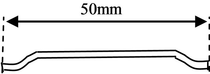
Figure 1. Hooked end steel fiber.
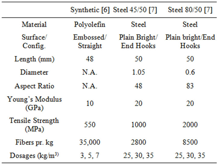
Table 1. Fiber properties table.
acteristic cylinder compressive strength: 30 Mpa; specified consistency (slump): 180 - 200 mm; w/c-ratio: 0.51 - 0.55. Coarse aggregate, with maximum size 22 mm was used in steel-fiber batches, and a maximum aggregate size of 16 mm in the synthetic fiber batches with 25% coarse aggregate reduction.
2. Field Work
Fibers were introduced to the test batches immediately after extracting samples from the truck drum at the delivery sites by filling the bucket, layer by layer, alternatively concrete and fibers, which were stirred into the sample by applying a drill-mounted mortar mixing device. 12 - 14 rings were poured in each of the four test-series’, each ring test requiring 9.3 liters of concrete. For each amount of fiber content, 4 rings were cast, Figure 2.
3. Laboratory Work
The outer steel ring of the ring mold was removed after 24 hours, and the top of the concrete was sealed by applying silicone.
Thus moisture could only escape from the concrete ring wall exterior surface. Strain gages were continually logging and recording data. The ring samples were visually inspected daily for crack occurrence, and crack dimensions were recorded accordingly, Figure 3.
3.1. Synthetic Fiber Results
No statistically significant decrease in crack widths with 3 kg/m3 of synthetic fibers was found. 5 kg/m3 resulted in statistically significant crack width reductions over the
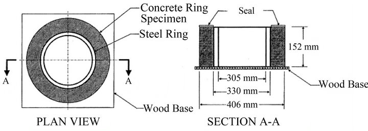
Figure 2. The steel ring mold.
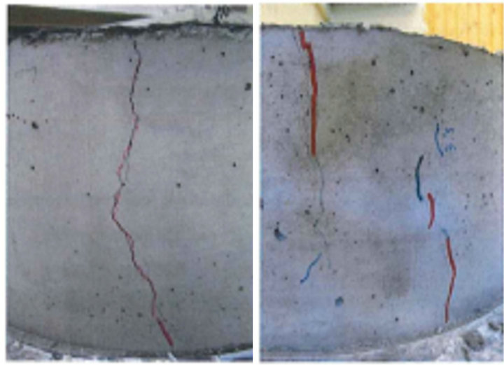
Figure 3. Typical crack configurations.
plain concrete ring samples. This trend continued when the fiber content reached 7 kg/m3, which was the highest content of synthetic fibers utilized in these experiments (Figure 4).
3.2. Steel Fiber Results
3.2.1. Steel 45/50 Fiber Content and Crack Widths
Samples containing 25, 30 and 35 kg/m3 displayed decreased crack widths as compared to the plain concrete rings, with a high statistical significance, although crack widths did not decrease with increasing fiber content, Figure 5.
3.2.2. Steel 80/50 Fiber Content and Crack Widths
Crack widths decreased with statistical significance with each increment in 80/50 fiber content: 0.18, 0.14 and 0.10 respectively at contents 25, 30 and 35 kg/m3 (Figure 6).
These fiber contents are higher than common practice with 80/50-fibers, but a direct weight comparison with the effect of 45/80-fibers was called for by the client, a major Norwegian building construction contractor) [9].
3.3. Combined Results
Comparisons were made between results from the plain concrete rings, the steel fiber rings and the synthetic fiber rings.
3.3.1. Crack Widths of the 36 Fiber Reinforced Rings, i.e. Both Steel and Synthetic Included, versus Those of the 5 Plain Concrete Rings
The average maximum crack width of all the fiber rein-
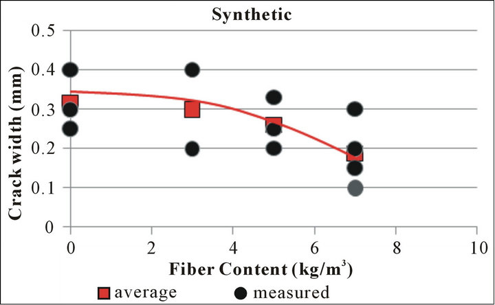
Figure 4. Synthetic fiber content versus crack widths. Ref. Appendix Tables A1 and A2.
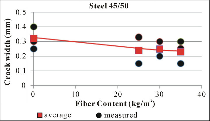
Figure 5. Steel 45/50 fiber content versus crack widths. Ref. Appendix Tables A2 and A3.
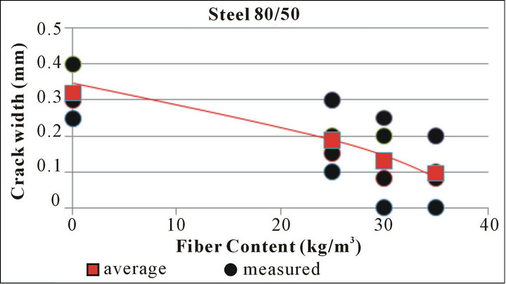
Figure 6. Steel 80/50 fiber content versus crack widths. Ref. Appendix Tables A2 and A4.
forced rings was 36% less than the average crack width of the plain concrete rings.
3.3.2. Crack Widths of the 12 Steel 80/50 and the 12 Synthetic Fiber Rings
The average maximum crack width of the 80/50 hooked end steel fiber reinforced rings was 0.14 mm, while the synthetic fiber ring average was 0.26 mm. This was a statistically significant nearly 50% crack width reduction using 80/50 hooked end steel fibers in lieu of synthetic fibers.
3.3.3. Crack Widths of the 12 Steel 80/50 and the 12 Steel 45/80 Concrete Rings
The average maximum crack widths of the 12 concrete rings containing the high aspect ratio steel 80/50 was found to be 0.14 mm while the average crack widths of the 12 concrete rings with the thicker steel 45/50 fibers was 0.24 mm. The difference was found to be a clearly statistically significant crack width reduction of nearly 40% using 80/50 fibers in lieu of 45/50 fibers at the same weight content.
4. Evaluation of Results
Basically, the results support the connotation that increased fiber volume [10] will decrease crack widths. The higher efficiency of steel fibers may reasonably be attributed to the steel/matrix bond being stronger than the synthetic/matrix bond, and to the increased mechanical pullout resistance provided by the hooked ends. The thinner 80/50 steel fibers are clearly more efficient at crack width reduction than the lower aspect ratio 45/50 steel fibers, at the same weight-amounts added, likely due to the higher number of the 80/50-fibers pr. unit weight, and, accordingly, greater contact area between the fiber surface and the matrix, pr. unit weight.
5. Conclusions
Sufficient data to indicate the following tendencies related to shrinkage-cracking were obtained:
• Samples containing 3 kg/m3 dosages of synthetic polypropylene fibers did not display a change neither in crack widths nor crack-patterns, compared to non-fiber rings.
• Steel 80/50 hooked end fiber mixes displayed narrower cracks-widths than mixes containing synthetic fibers.
• The high aspect ratio steel 80/50 hooked end fiber mixes displayed narrower cracks-widths than mixes containing the thicker steel 45/50 hooked end fibers, at equal weights added.
• 5 and 7 kg/m3 synthetic polypropylene fibers mixes and steel 45/50 hooked end steel fiber mixes containing 25, 30 and 35 kg/m3, yielded similar results.
6. Acknowledgements
The report upon which this article is based, was initiated by the Norwegian contractor Veidekke ASA*, represented by concrete technologists Lise Bathen* and Alf Egil Mathisen*, who made possible the execution of the field work by Petter E. Saga and Andreas Østvold, who, at that time, were engineering students at The University of Life Sciences. Professor Emeritus Egil A. Berge made a major contribution by advising on, and assisting in, the statistical significance evaluations of the laboratory results.
REFERENCES
- Transportation Research Board, “Control of Cracking in Concrete,” Report No. E-C 107, Transportation Research Center, Washington DC, 2006.
- Concrete Construction Staff, “Cracks in Driveways: What is Acceptable?” Concrete Construction Magazine, Chicago, 1997.
- N. Banthia, M. Azzabi and M. Pigeon, “Restrained Shrinkage Cracking in Fibre-Reinforced Cementitious Composites,” Materials and Structures, Vol. 26, No. 7, 1993, pp. 405-413
- J. Zhuang, “Evauation of Concrte Mix Design to Mitigate Early-Age Shrinking Cracks in Bridge Decks,” Washington State University, Pullman, 2009.
- C. O. Sørensen, P. E. Saga and A. Østvold, “Factors Affecting Fiber Distribution in Concrete and the Efficiency of Fibers on Crack Reduction,” Institute of Mathematics and Technology Report No. 47/2012, The Norwegian University of Life Sciences, Aas, 2012.
- Norm Tec AS, 2007. www.normtec.no
- S. A. Bekaert, 2012. www.bekaert.com/building
- EuroCode 2 Part 1-1, “Design of Concrete Structures,” 2010.
- A. Myren Synnøve, “Sprøytebetong Til Berg-Sikring,” (Rock Stabilizing Shotcrete), Tunnel Structures Section, Norwegian Public Roads Administration, 2011.
- E. Ösgür and K. Marar, “Effect of Steel Fibers on Plastic Shrinkage Cracking of Normal and High Strength Concretes,” Department of Civil Engineering, Eastern Mediterranean University/European University of Lefke, North Cyprus, 2010.
Appendix
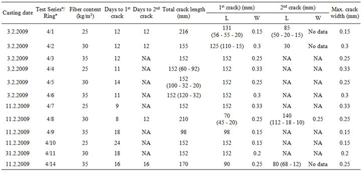
>Table A1. Barchip shogun synthetic fiber ring test results. Concrete: B30; w/c: 0.51 - 0.55; slump: 180 - 200 mm; Dmax = 16 mm; 25% coarse aggregate reduction.
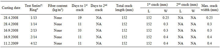
>Table A2. Plain concrete: B30; w/c: 0.51 - 0.55; slump: 180 - 200 mm; Dmax = 22 mm; no coarse aggregate reduction.
>Table A3. Dramix 45/50 steel fiber ring test results. Concrete: B30; w/c: 0.51 - 0.55; slump: 180 - 200 mm; D = 22 mm; nil coarse aggregate reduction.
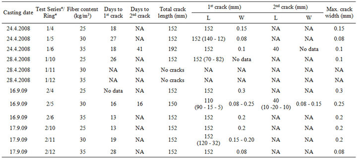
Table A4. Dramix 80/50 steel fiber ring test results. Concrete: B30; w/c: 0.51 - 0.55; slump: 180 - 200 mm; Dmax = 22 mm; nil coarse aggregate reduction.
NOTES
*This article is based on research sponsored and administered by The Concrete Innovation Center, COIN, which is one of the 14 R & D centers of the Research Council of Norway. By utilizing participant’s resources, COIN aims to assist its partners in developing solutions to the challenges encountered by the concrete industry.
*Email: firmapost@veidekke.no.