Modern Instrumentation
Vol.2 No.2(2013), Article ID:30814,7 pages DOI:10.4236/mi.2013.22005
Perturbation Functions in Computer Graphics
Synthesizing Visualization Systems Laboratory, Siberian Branch of the Russian Academy of Sciences, Russian Federation
Email: *sivser@mail.ru
Copyright © 2013 Sergey I. Vyatkin et al. This is an open access article distributed under the Creative Commons Attribution License, which permits unrestricted use, distribution, and reproduction in any medium, provided the original work is properly cited.
Received January 11, 2013; revised February 15, 2013; accepted February 25, 2013
Keywords: Geometric Objects; Perturbation Functions; Geometric Operations
ABSTRACT
The problem of real-time photorealistic imaging is discussed. New techniques for specifying free forms without their approximation by polygons are considered. Free forms based on the perturbation functions have an advantage of spline representation of surfaces, that is, a high degree of smoothness, and an advantage of arbitrary form for a small number of perturbation functions. Transformations of geometric objects are described for set-theoretic operations, projections, offsetting, and metamorphosis. We propose a GPU solution to render freeform objects at high frame rates.
1. Introduction
Nowadays real-time computer graphics oriented to 3D scene visualization has attained considirable success. However, even though a sufficiently high realism of realtime scene imaging has been attained, some problems are still present, for instance, it is necessary to store and visualize scenes containing a greater number of polygons than it is implemented in the present-day systems. Analysis of possible directions of evolution of a real-time visualization system shows that the easiest way to improve picture quality, i.e., to increase the number of polygons rendered per frame, is not the most effective one. Along these lines, the qualitative changes are difficult to achieve.
New techniques for specifying free forms without their approximation by polygons or spline-patches are considered. We suggest expanding the notion of primitives and making it possible to process them by easy and effective method without approximation by polygons. A method to display curved surfaces allows obtaining picture quality which cannot be achieved by the traditional means (even with great number of polygons) and is described below.
The geometric concept of virtual environment modeling using function-based objects can be described as an algebraic system [1].
where M is the set of geometric objects, F is the set of geometric operations, and W is the set of relations on the set of objects. Geometric objects are considered as closed subsets of n-dimensional Euclidean space En with the definition:
where f is a real continuous function defined on En.
A functionally defined object is completely defined by means of the real-valued describing function of three variables (x1, x2, x3) in the form of F(X) ³ 0, then the objects are treated as closed subsets of the Euclidean space En, defined by the describing function F(X) ³ 0, where F is the continuous real-valued function and X = (x1, x2, x3) is the point in En, defined by the coordinate variables. Here F(X) > 0 defines points inside the object, F(X) = 0 defines points on the boundary, and F(X) < 0 defines points that lie outside and do not belong to the object.
It is possible to describe complex geometry forms by specifying surface deviation function (of second order) in addition to surface basic function of second order (see Figure 1). Generally a function F(x, y, z) specifies surface of second order that is quadric
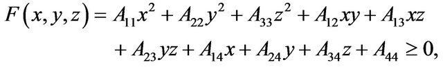
where x, y and z are spatial variables.
Were developed necessary algorithms and set of C++ classes: adaptive ray casting for scenes containing function-based objects (including OpenGL color/depth buffers compatibility); С++ classes for function-based objects representation; С++ classes for rendering of function-based objects; С++ classes interface classes provided to make the whole system to be easily extended to

Figure 1. Simple function-based object with two perturbation functions.
incorporate new algorithms and features.
For visualizing the binary adaptive ray casting algorithm was used [2]. The algorithm well-suited for modern GPU and provides good performance with good quality of results. The main task is fast finding the first intersection point with a surface that is only functionally defined. Compute Unified Device Architecture (CUDA) from NVIDIA was used. CUDA is a model of parallel programming. Together with a set of software, she allows to realize programs in language C for execution on a graphics accelerator.
2. Previous Works
The functional representation describes most accurately the object geometry and has the smallest size of the required data. Procedures of functional representation demonstrate compact and flexible representation of surfaces and objects that are the results of logical operations on volumes. Its disadvantage is complicated geometrical processing and visualization in real-time. Some kernels are described in [3-10]: Gaussian function, inverse function, inverse squared function, metaballs, soft objects, Wshaped quartic polynomial, Cauchy function and so on. Radial-based functions (RBFs) are described in [11-13].
A few rendering algorithms are described in [10]: raymarching, LG-surfaces, sphere-tracing algorithm, raytracing with interval analysis, etc. In [14] presented a method for displaying metaballs in real time on the GPU. In [15] a ray-casting rendering algorithm for algebraic surfaces was proposed. GPU ray-tracing of voxel data was introduced in [16]. In [17] a GPU-based rendering algorithm of algebraic surfaces was introduced. In [18] ray-tracing algorithm of 3D models based on radial functions on the GPU was proposed. In [19] presented a raycasting of discrete isosurfaces. In [20] presented a GPUbased sphere tracing algorithm of implicit surfaces. In [21] a GPU-based method for rendering F-rep (functionally represented) was presented.
3. Geometric Objects
We propose describing complex geometric objects by specifying the function of deviation (an implicit secondorder function) from the base surfaces [22]. The freeform is a composition of the base surface and the perturbation functions.
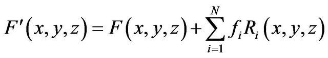
where fi is the form-factor; the perturbation function Ri(x, y, z) is found as follows
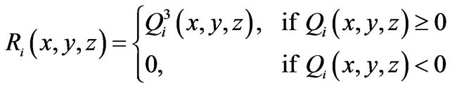
Herein, Qi(x, y, z) is the perturbing quadric.
Since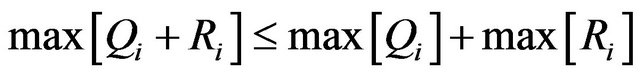 , for estimating the maximum Qi on some interval we have to calculate the maximum perturbation function on the same interval. The obtained surfaces are smooth (see Figures 2 and 3), and creation of complex surface forms requires few perturbation functions.
Figure 4 shows a result of modeling a scene object by means of free forms, whose description required 4 K byte information, which is 500 times less than the polygonal
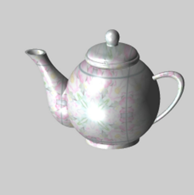
Figure 2. Function-based object with perturbation functions.

Figure 3. Function-based objects with perturbation functions.
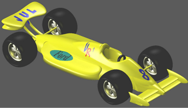
Figure 4. Complex function-based geometric object.
description that would take 2 M byte information. Thus, the problem of object construction reduces to the problem of quadric surface deformation in a desired manner rather than to approximation by primitives (polygons or patches represented by B-spline surfaces). In addition, while solving the descriptive function in the form of inequality F(X) ³ 0, we can visualize not only the surface but also the internal structure of the object.
4. Geometric Operations
Two major types of elements of the set of geometric objects are simple geometric objects and complex geometric objects (see Figures 4 and 5). A complex geometric object is a result of operations on simple geometric objects [23].
The set of geometric operations F is expressed mathematically in the following form:
 where n is the number of operation operand.
Let the object G1 be defined as f1(X) ³ 0. The unary operation (n = 1) of the object G1 means operation G2 = F¡(G1) with the definition
 where y is a continuous real function of one variable. Let us consider the following unary, binary operations and relations in more detail.
4.1. Projections
Projections of a solid onto three orthogonal planes yield us a representation of its different sides. The projection of 3D solid onto the coordinate plane is considered as a union of sections of the solid by planes parallel to the coordinate plane at a sufficiently small distance from each other. We will a mathematical description of the process for a space of arbitrary dimension. Let the initial object G1 Ì En be described by the function
and its projection G2 Ì En–1 be described by the function
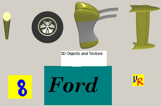
Figure 5. Simple geometric objects.
The object G2 can be defined as a union of sections of the object G1 by the hyper plane xi = Cj, where Cj+1 = Cj + Dxi, j = 1, N and C1 = ximin. Let be the function for the section. As a result, the function for the projection at Dxi®0 is a union of all functions f1j:
 .
.
In the realization of this operation for the whole scene we fixed one coordinate, depending on what projection had to be obtained.
4.2. Offsetting
The offsetting operation was implemented by transformation of perturbation function coefficients. Thus, one can created an enlarged or diminished copy of the initial object, i.e., makes positive or negative offsetting. For example, solid beats can be simulated. Let the initial object be defined by the function f(X) > 0, then in the case of this operation, the obtained solid will be described by the function F = f(X) + C, where С < 0 determines the negative offsetting (compression) and C > 0 determines the positive offsetting (extension). Otherwise, adding together the positive or negative constant and the free term of the perturbation function yields extension or compression of the whole object.
4.3. Set-Theoretic Operations
Let the objects G1 and G2 be defined as f1(X) ³ 0 and f2(X) ³ 0. The binary operation (n = 2) of the objects G1 and G2 means operation G3 = F¡(G1,G2) with the definition
 where y is the continuous real function of two variables. Let us dwell on the binary operations: set-theoretic operations and 3D metamorphosis (morphing).
For function-based objects on the bases of perturbation functions we propose the following. To create a complex scene, one should describe in it a certain number of primitives necessary for a concrete task. The rendered object with which the rendering algorithm interacts by means of query represents the whole 3D scene. Hence, the geometric model should allow designing of objects and their compositions of infinite complexity. This is primarily achieved by means of Boolean operations of uniting and intersection.
4.4. 3D Metamorphosis
This operation transforms the first defined object into second with obtaining multiple intermediate forms. The term originates from the word metamorphosis and refers to the animation technique in which one pattern is gradually transformed to another. During the metamorphosis (morphing), the initial pattern is gradually transformed to the final one.
A sequence of frames of transformation of one object to another is generated by means of the initial, final, and key intermediate models.
Let F1 and F2 be values of the perturbation functions of the first and second objects, respectively. Then the resulting perturbation function is calculated as follow:
 where β is the positive continuous function.
For function-based objects with the use of perturbation functions, one can perform 3D morphing of nongomeomorphic objects.
4.5. Twisting
Twisting is a solid deformation being a particular case of bijective mapping which serves for defining deformations of initial objects. For twisting of the initial solid we found and transformed its coordinates x, y, z.
4.6. Global and Local Deformation
First thing that is necessary to state is that if we want to propagate the deformation it should be somehow added to all object that it affects. Actually the current scene-tree is organized so that it is no possibility to add object only by referencing i.e. without copying. This is done for avoiding situations when being changed somewhere the object unintentionally change the other part of the scene that referenced to it too. Thus the additional perturbations should have such parameters to assure the part-per-part connectivity for each pair of the object the perturbation affects. In this case it will be looked as one perturbation.
4.7. Sweeping
We consider the swept volume as a projection of a moving solid from the 4D (x,y,z,t) space to the 3D (x,y,z) space. Then we draw the solid each time new coordinates that were changed by the proper law. In so doing, the previous images are stored in the memory and used to obtain the result of swept volume. The newly formed figure is a union of images of the swept solid for different positions.
4.8. Relations
A binary relation is a subset of the set . It can be defined as

The examples of binary relations are inclusion, point membership, interference or collision.
Collision Detection
Collision detection is a complicated problem solved in various computer programs. This means that for each animation frame, one should test whether any two or more objects collided. The collision detection algorithm described in [24] is based on the relation of object intersection and uses the Sobol’s quasirandom sequences and the spiral quadratic search for detecting nonnegative values of the function defining the intersection. In so doing, body, confining spheres are used to define the region of search. This algorithm does not always result in collision detection, i.e., the algorithm does not ensure detection of event as stated by authors. Moreover, a drastically different time is required for different collisions.
We propose original way of collision detection without using any bounding volumes around each object and preprocessing stage. For objects based on perturbation functions the object collision is detected in a constant time for collisions of different complexity, and the detection of events is absolutely ensured [25]. This way of collision detection is based on the relation of object intersections, function representation with perturbation functions and on the recursive object space subdivision for search the contact point of the objects.
5. Rendering
We consider the geometric object that has the property of answering the request on intersection with a bar. The negative answer guarantees that the object is not intersected and has no common points belonging to the intersection is done by recursive subdivision of the space inside the cube defined by boundaries of ±1 along each coordinate (see Figure 6).
The center of the cube matches the origin of the model coordinate system M whereas the plane Z = −1 coincides with the screen plane. Coordinate system in which the algorithm subdivides cubic volume is called work or model space and is denoted M (see Figure 6). Coordinate system with camera (viewer) in its origin and viewing frustum is denoted P. In the given work we suggest to use the binary adaptive ray casting algorithm for ray-
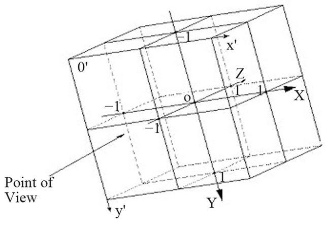
Figure 6. The model coordinate system (M) in which the space inside the cube is subdivided.
surface intersection calculation. The general block-scheme algorithm is shown on Figures 7 and 8. Starting from the observer’s eye, a viewing ray (a bar) is traced through the object space for each pixel on the view plane.
For each bar-surface intersection test are executed. If the object intersects with given bar, then bar subdivides further. Otherwise, we exclude bar from subdivision. Using results of intersection test, we perform subdivision of sub bars that fall within the quadric completely or, probably, partially, and the knowingly external sub bars are eliminated from processing.
On some recursion level we determine first point, which contains a surface.
After a finding of a point of ray-surface intersection, we calculate normal and color.
Calculation of all color components of a pixel is performed in the same manner by the following formula:
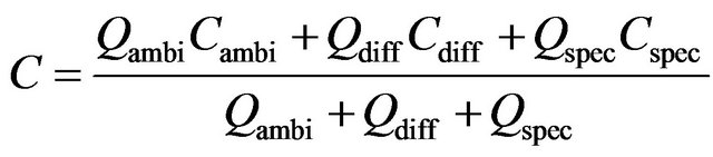
where “ambi” refers to characteristics of ambient light, whereas “diff” and “spec” refer to the diffused and specular components of reflected light, respectively; C are the color components; Q are the weight coefficients. Color components are calculated by a vector light model. Four vectors are involved in the calculation: normal to the surface (n), vector to the light source, reflected light direction (r) and vector to the viewer (v):
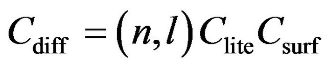
Clite is the light source color; Csurf is the surface color;
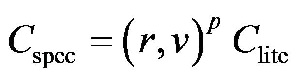
where p is the reflection coefficient.
In [26,27] we proposed a texture memory management policy that substitutes the classical assignation policy of one texel per voxel, applied for the volume representation in texture space. The texture is an object (not mapped) changing the properties of another object. The feature of the texture is that any object may be the texture. A supplement to the data structure with consideration of the
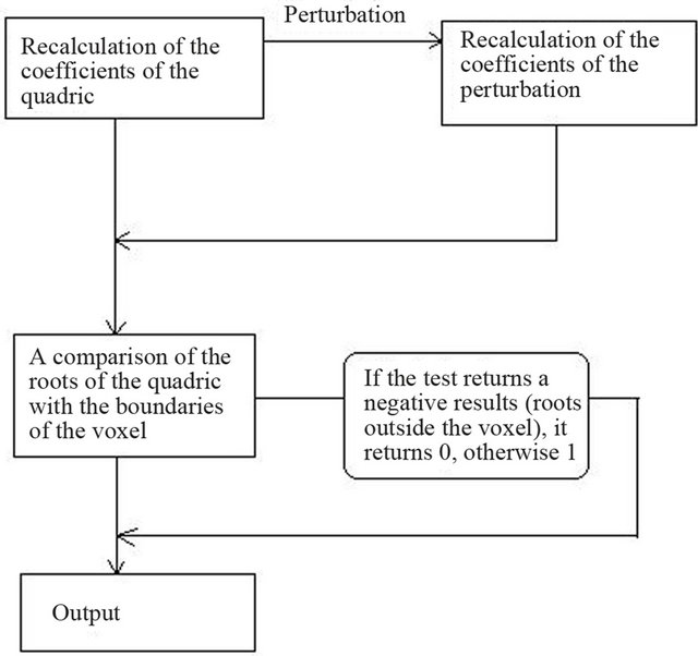
Figure 7. The general block-scheme: ray-surface intersection calculation.
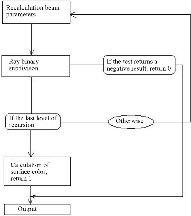
Figure 8. The general block-scheme: binary subdivision of a bar.
structure is that each object can have a reference to another object being a texture for it.
In our work two applications which visualize free form objects based on perturbation functions have been realized. The first uses only CPU for calculations. The second uses GPU for calculation of depth, normal and illumination, and CPU for geometric transformations. For image display both versions used DirectX. Testing of productivity of the offered variants of realization has been made. Testing was made on the computer with processor Intel Core2 CPU E8400 3.0 GHz, and GPU GeForce 8800 GTX. Performance strongly depends on the speed of memory.
In [15] ray casting algebraic surfaces is described. That by means of a usual polynomial to set a difficult surface it is necessary to increase its degree. In a case with Bezier curves that also is not guaranteed, is how much exact initial function will be approached to this curve. One more disadvantage of this method is what to translate such object in other co-ordinate systems not a simple problem. Therefore creation of dynamical scenes is complicated.
In [20] presented another method for finding the first intersection of the surface with the ray. It is based on the usual step by step tracing. The difference is that the step size is not constant and is chosen at each step. At each step, is a ball centered at the current point on the ray. The radius of the ball is selected so that no point of not lying inside it. Selecting a ball can make a step in the direction of the ray at the radius of the ball. It is obvious that the radius should be the greatest. The process continues until the radius does not exceed the selected error. Thus, the search speed is not slower than normal step by step search with a step equal to the size of the error. But in almost all cases, using this algorithm, we can find a point of intersection for a smaller number of steps. However, finding a suitable radius is a complex task. For static scenes preliminary data processing is used. But such method can be applied effectively only when objects are static. That is when the form and scale of objects does not change.
6. Conclusion
The freeform representations created by means of the perturbation functions have the following advantages: fewer surface for mapping curvilinear objects, short database description, fewer operations for geometric transformations and data transfer, simple animation and deformation of objects and surfaces, and a wide spectrum of applications (interactive graphics systems for visualizing function-based objects, CAD 3D simulation systems, 3D web visualization, etc.). We have investigated various geometric operations on functionally defined objects on the basis of the perturbation functions. We have analyzed the collision detection algorithm by means of recursive object space subdivision. We may conclude that in the proposed function-based object collision detection algorithm, the collision is always detected and does not depend on the relative position of collided objects and parts of their surfaces, i.e., such an algorithm guarantees detection of the event, which has been proved both experimentally and theoretically. Modern high-performance parallel multiprocessor systems graphics accelerators provide an opportunity to expand methods of three-dimensional visualization of the fourth dimension - time. As a result, it is possible to implement new effects on geometric objects, caused by the introduction of operations on functions in real time.
REFERENCES
- A. Pasko, V. Adzhiev, A. Sourin, et al., “Function Representation in Geometric Modeling: Concepts, Implementation and Applications,” The Visual Computer, Vol. 11, No. 6, 1995, pp. 429-446.
- S. I. Vyatkin, M. Gorodilov and B. S. Dolgovesov, “GPU-Based Binary Adaptive Ray Casting for Freeform Objects with Perturbation Functions,” Proceedings of the IASTED International Conferences on Automation, Control, and Information Technology, Novosibirsk, 15-18 June 2010, pp. 223-228.
- J. McCormack and A. Sherstyuk, “Creating and Rendering Convolution Surfaces,” Computing Graphics Forum, Vol. 17, No. 2, 1998, pp. 113-120. doi:10.1111/1467-8659.00232
- J. Bloomenthal and K. Shoemake, “Convolution surfaces,” ACM SIGGRAPH Computer Graphics, Vol. 25, No. 4, 1991, pp. 251-256. doi:10.1145/127719.122757
- G. Sealy and G. Wyvill, “Smoothing of Three-Dimensional Models by Convolution,” Proceedings of Computer Graphics International, Pohang, 24-28 June 1996, pp. 184-190.
- J. F. Blinn, “A Generation of Algebraic Surface Drawing,” ACM Transactions on Graphics, Vol. 1, No. 3, 1982, pp. 235-256. doi:10.1145/357306.357310
- H. Nishimura, M. Hirai, T. Kawai, T. Kawata, I. Shirakawa and K. Omura, “Object Modeling by Distribution Function and a Method of Image Generation,” The Transactions of the Institute of Electronics and Communication Engineers of Japan, Vol. J68-D, No. 4, 1985, pp. 718- 725.
- G. Wyvill, C. McPheeters and B. Wyvill, “Data Structure for Soft Objects,” The Visual Computer, Vol. 2, No. 4, 1986, pp. 227-234. doi:10.1007/BF01900346
- J. Bloomenthal, “Modeling the Mighty Maple,” Computer Graphics, Vol. 19, No. 3, 1985, pp. 305-311. doi:10.1145/325165.325249
- A. Sherstuyk, “Fast Ray Tracing of Implicit Surfaces,” Computer Graphics Forum, Vol. 18, No. 2, 1999, pp. 139-147.
- A. G. Bors and I. Pitas, “Object Classification in 3-D Images Using Alpha-Trimmed Mean Radial Basis Function Network,” IEEE Transactions on Image Processing, Vol. 8, No. 12, 1999, pp. 1744-1756. doi:10.1109/83.806620
- J. C Carr, et al., “Reconstruction and Representation of 3D Objects with Radial Basis Functions,” Proceedings of the 28th Annual Conference on Computer Graphics and Interactive Techniques, Los Angeles, 12-17 August 2001, pp. 67-76.
- S. Matej and R. M. Lewitt, “Practical Considerations for 3-D Image Reconstruction Using Spherically Symmetric Volume Elements,” IEEE Transactions on Medical Imaging, Vol. 15, No. 1, 1996, pp. 68-78. doi:10.1109/42.481442
- Y. Kanamori, Z. Szego and T. Nishita, “GPU-Based Fast Ray Casting for a Large Number of Metaballs,” Eurographics, Vol. 27, No. 2, 2008, pp. 351-360.
- M. Reimers and J. Seland, “Ray Casting Algebraic Surfaces Using the Frustum Form,” Eurographics, Vol. 27, No. 2, 2008, pp. 361-370.
- J. Kruger and R. Westermann, “Acceleration Techniques for GPU-based Volume Rendering,” 14th IEEE Visualization, Seattle, 24-24 October 2003, pp. 38-42.
- C. Loop and J. Blinn, “Real-Time GPU Rendering of Piecewise Algebraic Surfaces,” Proceedings of ACM SIGGRAPH, Vol. 25, No. 3, 2006, pp. 664-670.
- A. Corrigan and H. Quynh Dinh, “Computing and Rendering Implicit Surfaces Composed of Radial Basis Functions on the GPU,” International Workshop on Volume Graphics, 2005, pp. 187-195.
- M. Hadwiger, C. Sigg, H. Scharsach, K. Buhler and M. Gross, “Real-Time Ray-Casting and Advanced Shading of Discrete Isosurfaces,” Computer Graphics Forum, Vol. 24, No. 3, 2005, pp. 303-312. doi:10.1111/j.1467-8659.2005.00855.x
- G. Liktor, “Ray Tracing Implicit Surfaces on the GPU,” Computer Graphics and Geometry, Vol. 10, No. 3, 2008, pp. 36-53.
- O. Fryazinov and A. Pasko, “Using GPU for Interactive Ray Casting Functionally Represented Models,” Computer Graphics and Geometry, Vol. 9, No. 1, 2007, pp. 1-17.
- S. I. Vyatkin, “Complex Surface Modeling Using Perturbation Functions,” Optoelectronics, Instrumentation and Data Processing, Vol. 43, No. 3, 2007. pp. 40-47. doi:10.3103/S875669900703003X
- S. I. Vyatkin, B. S. Dolgovesov and A. T. Valetov, “Geometric Operations for Functionally Defined Objects Using Perturbation Functions,” Optoelectronics, Vol. 40, No. 1, 2004, pp. 65-73.
- V. V. Savchenko and A. A. Pasko, “Collision Detection for Functionally Defined Deformable Objects,” In: B. Wyvill and M. P. Gascuel, Eds., The First International Workshop on Implicit Surfaces, Grenoble, 18-19 April 1995, pp. 217-221.
- S. I. Vyatkin, B. S. Dolgovesov and A. S. Korsun, “Collision Detection of Functionally Defined Objects in Computer Graphics Tasks,” Optoelectronics, Instrumentation and Data Processing, Vol. 39, No. 6. 2003, pp. 119-126.
- S. I. Vyatkin and B. S. Dolgovesov, “A 3D TextureBased Recursive Multi-Level Ray Casting Algorithm,” Proceedings of the Second IASTED International MultiConference on Automation, Control, and Information Technology, Novosibirsk, 20-24 June 2005, pp. 92-97.
- S. I. Vyatkin, “A 3D Texture-Based Rendering Algorithm,” Computer Graphics and Geometry, Vol. 8, No. 3, 2006, pp. 65-78. http://www.cgg-journal.com/2006-3/05.htm
NOTES
*Corresponding author.