Modern Instrumentation
Vol. 1 No. 4 (2012) , Article ID: 23660 , 4 pages DOI:10.4236/mi.2012.14006
Development of a Low Cost Pulsed Laser Deposition System for Thin Films Growth
1Centro Láser de Ciencias Moleculare, Departamento de Fisicoquímica, Facultad de Ciencias Químicas, Universidad Nacional de Córdoba, Ciudad Universitaria, Córdoba, Argentina
2Grupo de Ciencia de Materiales, Facultad de Matemática Astronomía y Física, Universidad Nacional de Córdoba, Ciudad Universitaria, Córdoba, Argentina
3Instituto de Física Enrique Gaviola, Consejo Nacional de Investigaciones Científicas y Técnicas (CONICET), Córdoba, Argentina
Email: *omarcos@famaf.unc.edu.ar
Received August 16, 2012; revised September 26, 2012; accepted October 11, 2012
Keywords: Pulsed Laser Deposition; Thin Film; Multilayer
ABSTRACT
Pulsed Laser Deposition (PLD) is a powerful technique to grow thin films. Oxides, Magnetics and superconducting materials have been obtained by PLD and theirs properties are strongly dependent of deposition parameters. The construction of a simple and cheap PLD system that is suitable for growing various thin films, including magnetic materials, controlling some deposition parameters is presented. The design characteristics and construction are presented for each one of the devices that compose this PLD system. The equipment has the possibility of carrying out films deposition using up to five targets under controlled atmosphere and substrate temperature. The system also allows controlling the cool off sample time after growing up films at high temperatures. A wide range of relative speeds between target and substrate axial rotation can be externally controlled. With the configuration and the dimensions adopted in their construction, a PLD system of great experimental flexibility is achieved, at a very low cost regarding the commercial systems. To evaluate their performance and effectiveness, the deposition characteristics of a BaFe12O19 film on (0001) sapphire substrate is presented.
1. Introduction
Thin films are prepared using diverse methods such as sputtering [1], sputtering by radio frequency [2], sol-gel deposition [3], liquid-phase epitaxy [4], Metal Organic Chemical Vapor Deposition (MOCVD) [5], Molecular Beam Epitaxy (MBE) [6] and Pulsed Laser Deposition (PLD) [7] among others.
PLD, is one of the most versatile and powerful techniques to produce thin films. Their main characteristics are: 1) high stoichiometric reproduction of complex materials into thin films, 2) the evaporated species obtain an important kinetic energy (100 eV to 500 eV), which improve its redistribution on the substrate surface, contributing to superficial mobility, obtaining less rough films, besides allowing make depositions at smaller temperatures than conventional ones [8], 3) the target material does not require important pre-processing, 4) it allows the films growth of materials with high fusion temperature, 5) films are obtained with high reproducibility, and high deposition rates [7-13].
The PLD process basically consists in focusing the pulsed laser beam in a material (target) to obtain their evaporation. The evaporated material is ejected into a perpendicular direction to the target surface, forming a plume. This plume is a hot plasma (6000˚C K approximately), that soon is deposited in a substrate, where the film grows up pulse by pulse.
The physical properties of films grew up by PLD are dependent on the target material, the substrate and also strongly dependent on the parameters of the laser (fluence, wavelength, pulse duration, repetition rate, spot of focalization form and size and laser polarization), as well as on the pressure, atmosphere, substrate temperature and target-substrate separation.
A system of deposition having the properties referred to above, can be purchased at a high cost, however in this article we show the development and construction of a cheap, versatile thin films growing system by PLD. The main parts of the system are essentially: 1) vacuum chamber, 2) rotary multitarget holders, 3) rotating substrate holder inside of a resistive heater, 4) gas delivery system for depositions with reactive atmospheres, 5) controller module for targets position and rotation speeds of targets and substrate.
The vacuum system is a mechanical pump with a diffusing oil system CINDELVAC Model ISOLAB-700-2 which allows working to a minimum pressure of 10-7 Torr with a cryogenic trap. A rheostat (0 - 250 V) with maximum current of 12A is the power source of the resistive heater. For the spectroscopic control of the ablation plume [14], two Ocean Optics HR400 spectrometers, were employed. They work respectively in the 200 - 400 nm and 400 - 600 nm range, with 1 nm of resolution. For growth in a controlled atmosphere, the chamber pressure can be stabilized by means of a mass flow controller.
To test the system performance, films of BaFe12O19 was deposited on (0001) sapphire substrate, using a Big Laser Sky Quantel CFR Nd-YAG laser.
2. Design and Construction
2.1. Considerations for the PLD System Design
Design characteristics of a PLD system will depend on the film material to be deposited and the desired physical properties. For example, some films must be deposited in vacuum and other ones under a controlled atmosphere [15]. Also another important factor is the substrate deposition temperature. Some characteristics are common to all PLD systems: 1) zoments the particles ejection and when arrive to the substrate damage it or provide a very rough film. The target movement diminishes the superficial damage, lowering the number of pulses in each impact point. Also allows avoiding another not wished effect, such as the plume directional change due craters or furrows [11], 2) for the substrate, its movement contributes to a more homogenous film growth, by reducing the plume direction fluctuation effect and preferential direction of ablated species effect [13], 3) the substrate heater is a fundamental part of the system in order to obtain a high quality growth. The optimal working temperature will depend on the material to deposit and the desired physical properties. For example, the BaTiO3 deposition on MgAl2O4 at 1050˚C [16], or ITO deposition on glass at 80˚C - 180˚C [17]. A good substrate heater system should be able to control the substrate temperature during the deposition, as well as the cooled off ramp for determinate materials [9].
2.2. Ablation Chamber
The dimension of the vacuum chamber must allow containing the different PLD system devices and should not be too large because it is a disadvantage for deposits into controlled atmosphere. In the present case, cylindrical shape was selected to obtain a greater experimental versatility. Their dimensions are 40 cm diameter and 23 cm height. In Figure 1 it is outlined the chamber with its main components.
The materials used in their construction were iron (low cost material) and aluminum; this last one was used only in the supports of components. As it is showed in the superior part of Figure 1, the chamber has eight lateral access windows, arranged forming 45˚ angles among them. These windows are occupied, by: 1) entrance of the laser beam (glass window), 2) pressure (vacuum) sensor, 3) gas flow line, 4) refrigeration line, 5) optical fiber, 6) vacuum pump, remaining two free entrances for future devices. The acrylic superior window 7), allows to visually checking the deposition in real time. The location of three motors is indicated in 8). One motor shift the target position and the other ones move axially targets and substrate. The target holders are indicated in 9) and the substrate holder and heater in 10). The access destined to the electrical current for the resistive heater is showed in 11). All these accessories are detachable, providing a greater flexibility. The target holder and the substrate holder-heater are attached into a platform joint to the chamber cover, which contributes a significant improvement for targets and substrate change. The device also allows changing angular dispositions between
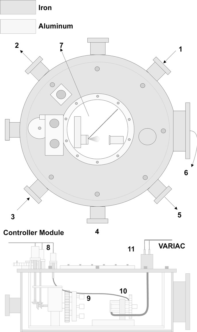
Figure 1. Outline of ablation chamber.
laser beam and target surface, and the distance between target and substrate.
A refrigeration system was incorporated to control the temperature inside the chamber when depositions at high temperatures are made, it is a copper sewer, with a diameter of 0.6 cm, into which water circulates, distributed uniformly behind the heater and patch to the inner surface of the chamber. The refrigeration system improves the deposition conditions, avoiding the additional heating of targets and rotation system. The design selected for the chamber has the advantage that with minimum modifications, diverse changes in the deposition parameters are obtained, such as: incidence angle of laser beam with the surface of the target, variations in the angle between target and substrate for deposits “off-axis” or “on-axis”. The target-substrate separation can be selected in a rank of 2.5 cm to 8 cm. The dimensions and disposition of windows allow the incorporation of extra components, for example, devices to generate electric fields for a hybrid DC-field enhanced PLD-process [18].
2.3. Multi-Target System
The multi-target carousel and the manipulator system were constructed contemplating the necessities to make high quality single or multi-layers deposits. In their design it is necessary to consider number of targets and final dimension of the target holders, which must be inside the vacuum chamber. The system was build with five target holders, maintaining the typical dimensions (1 to 1.5 cm of diameter) of the targets used in PLD. In Figure 2 is outlined the multitarget system. The target holders, fully detachable, facilitate the change of target material by the window removable viewfinder (item 7 in Figure 1). The support and platform were constructed in aluminum, the axles in bronze and transmission gears in stainless steel. Target holders allow to lodge a cylindrical target up to 1.25 cm of diameter and up to 0.7 cm of height. The axial movement of each target holder is provided by a system of six gears (one central, and five as satellites) located in the support disc of target holders, and two gears for the communication with the motor for axial movement.
The positioning of the targets is carried out by means of three pairs of gears, one of them is external, and the other two inside the chamber and the movement is also imposed by a motor. The pair of external gears is outlined in Figure 3. The motor (C in Figure 3), allows positioning the selected target in front of substrate, by means of the disc (See A in Figure 3).
The positioning is controlled by a switch (B in Figure 3), that stops the motor when the programmed position is reached. The communication of this gear with the targets is carried out by means of two axes, in form of L, (Figure 1). Each one of these targets can rotate around its axial axis with 16 different speeds. The rotation control mechanism is explained in Section 2.4.
2.4. Substrate Holder and Heater
The substrate holder allows the rotation and incorporation of a heater system. It is a copper cylindrical body, which in one of the ends has the substrate holder cavity and in the other one has a gear, to rotate it (see Figure 4). The corresponding motor is connected by a steel wire allowing the movement toward the front, varying the distance target-substrate between 2.5 - 8.0 cm and beside allows changing off-axis or on-axis configuration easily.
The system has 16 rotation programmable speeds, allowing to change the speed and direction of rotation during the deposition process. As mentioned before, in the technique of PLD for oxide films, it is of great importance that the substrate remains at an elevated temperature, and this is the reason why it is needed a substrate holder heater. In literature are found different methods to warm up substrate in PLD techniques, such as heating by halogenous lamps [19], heating by laser [20], and heating by radiative heater [21]. In the present work, it was decided on a radiative heater, because its greater durability and low cost.
The substrate holder nucleus is wrapped up with a resistive twin-core wire Watlow 62H24A6X, 61 cm of length and 1.575 mm of diameter, which has a sheath of InconelÒ and cold tips, the total resistance is 63 ohm. The substrate holder nucleus and the resistive wire are inside of a refractory cylinder to diminish the dissipation
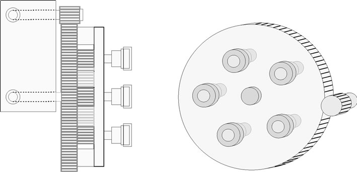
Figure 2. Scheme of the multi-target and manipulator system.
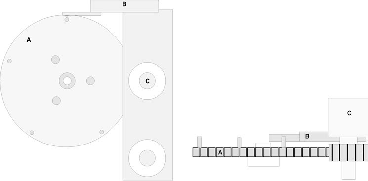
Figure 3. Movement target control system.
and to allow reaching the high temperatures of interest. The dimensions of the refractory cylinder are: 42 mm external diameter, 28 mm internal diameter and 70 mm of length. The copper nucleus is cylindrical with 18 mm diameter, and 22 mm in the substrate holder end where it can be fixed a substrate of 5 × 5 mm2, 10 × 10 mm2 or 5 × 10 mm2. Once the substrate is located in the cavity adapted according to their dimensions, it is supported by a ring that covering their vertexes, leaving free the area of interest. In this way complications are avoided that appears with other methods of fixation, like for example by silver painting [22], which requires a previous thermal processing and it disables to determine the mass of the film.
Usually, it has been found inconvenient in systems with hot mobile substrates due to the warming up effects on the gears system. In these systems the dimension gears are such that allow diminishing this effect.
The substrate holder cavity has a smaller diameter than the corresponding to the cylindrical nucleus and with this configuration and the high thermal conductivity of copper, the substrate is exposed to a minimum temperature gradient. It is one of the most important factors for the epitaxial growth of films and not always is well contemplated. Another advantage of this heater is the significant smaller cost, in comparison with commercial heaters. The temperature was measured with a K type thermocouple and a temperature vs time calibration was carried out for a power of 175 W in the heater (described in Section 3).
2.5. Control Module and Motors
Each target holder can be positioned exactly confronted with the substrate and the initial position is used as reference. The control module is computer and the operation parameters of the module can be set previously to the deposition, and follows this order: location of the target, movement of the substrate holder (On/Off, time of turn, speed and direction of rotation), movement of target holder (On/Off, speed and direction of rotation). In addition it is possible to load a sequence and to keep it in non-volatile memory. The transmitting information is: time, direction of rotation, speed of turn, and position. All parameters could be modified while the deposition process is performing. For the movement of the substrate holder and the movement of target, an Ignis MR82-6 0704 motor was employed, operating at 6 RPM, and for the shift of position of the target an Ignis MR82-17 0705 with 17 RPM was employed. All of them operate at 12 V and 0.4 A.
2.6. Ring Nozzle
The scheme configuration of the “ring-nozzle” experimental setup is showed in Figure 5. The “ring-nozzle” is located between the target and the substrate, allowing passing the plume through its interior. The ring is fixed to the substrate holder and keeps the gas flow direction towards the substrate. Their dimensions are internal and external diameter, 3.6 cm y 6.0 cm respectively and thickness 1.1 cm. This accessory is useful to control the local atmosphere near the substrate and to control the cooling rate of the substrate after deposition. In previous studies it was found that the flow of gas is directed toward the substrate and not towards the target to improve the incorporation of oxygen in the film growth [23]. For example using a reactive gas such as O2, could help to replicate the stoichiometric of the target into the film [9].
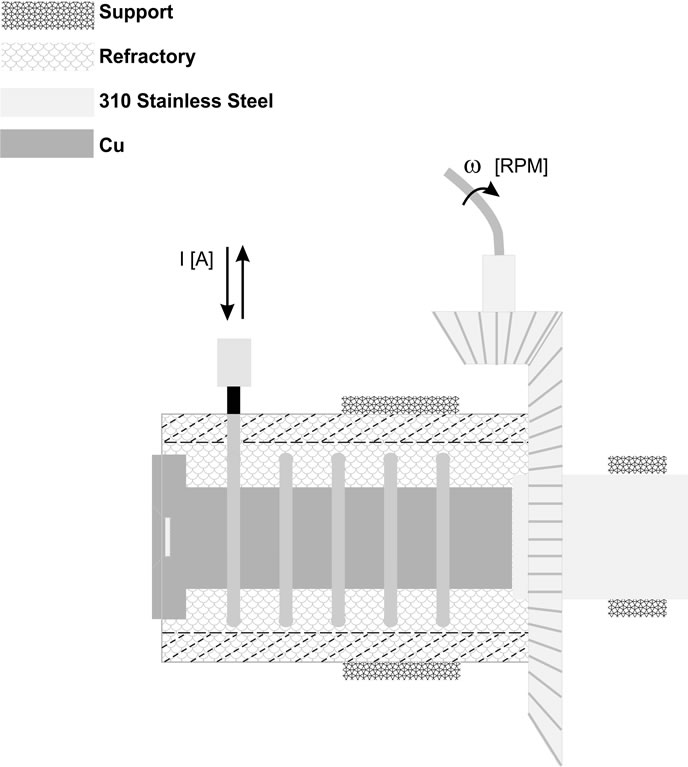
Figure 4. Scheme of the substrate holder.
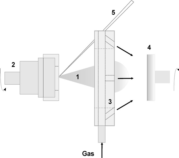
Figure 5. Scheme of experimental setup of the “ring-nozzle”, (1) plume, (2) target, (3) ring-gas, (4) substrate, and (5) beam laser.
2.7. Deposition of Thin Film
To evaluate the system a deposit of barium ferrite on sapphire (0001) substrate was made. For the material of the target a commercial Ba-ferrite magnet was used. The material was milled in a ball mill at 200 rpm, in air atmosphere, during 5 hs to obtain nearly monosized distribution. The powder was pressed at 600 MPa, to obtain a cylindrical pellet of 3 mm height and 10 mm of diameter. To increase their hardness, these targets were thermally treated in two stages: 550˚C for 15 minutes, then, at a rate of 7˚C/min was warmed up to reach 1000˚C, maintaining this temperature by 4 hs, then was cooled down slowly. The BaFe12O19 composition of the target was corroborated by X-Ray Diffraction (XRD). The used laser was a Nd-YAG with wavelength = 532 nm, 6 ns of duration of pulse, 10 Hz repetition rate, obtaining, once focalized the beam in the target, a fluence of 22.5 J/cm2. The target-substrate distance was 35 mm and the deposition time 40 minutes. During the deposit, the chamber was maintained in vacuum and the temperature of the substrate was fixed at 300˚C. Later on, the deposited film was heat treated, keeping them at 1000˚C during 2 hs. in air atmosphere. The magnetic behavior of the film was measured with a Vibrating Sample Magnetometer (VSM). In addition studies by means of Atomic Force Microscopy (AFM) and XRD were made. These results are presented in Section 3.3.
3. Results and Discussion
3.1. Substrate Holder and Target Holder
The rotation velocity of target and substrate can be selected over 16 options in both directions. Table 1 exhibits the rpm that can be programmed in target holder and in the substrate holder. It is observed that the frequencies for the target are between 10 to 24 RPM, in both directions of rotation. And for the substrate holder, the turn frequencies are between 0.9 and 2.1 RPM, in addition to the change of direction of rotation. The increase in the speed is essentially linear with respect to the number of option.
Finally, complete content and organizational editing before formatting. Please take note of the following items when proofreading spelling and grammar.
3.2. Heater
As it was mentioned in Section 2.3, it was carried out a study of the substrate heating according to the time employed in reaching the maximum temperature as well as the time necessary to cool off after the deposition is finished. Also unforced and forced cooling is considered. The use of a VARIAC allows to control the temperature of the substrate by means of the voltage applied to the heater. To measure substrate temperature a K type thermocouple is used. The measured temperature vs time when applying 175 W of power to the heater (for our configuration 105 V) is shown in Figure 6 and the inset figure shows the evolution of pressure chamber vs time while the substrate is warming up. The effect of the heating on the pressure is very significant and should be considered to select the correct working pressure. The cooling process can be forced or unforced depending on the desired characteristics of the film. For the unforced cooling, the heater current is cut off and the substrate cool down until it reaches room temperature. A typical cooling curve of the substrate, from 650˚C down to room temperature, and for two forced cooling process are shown in Figure 6. The forced cooling arises from a gas flow over the film surface, cooling down at greater rates. Also the system allows controlling that the rate of cooling combining its action whit the substrate heater current.
The cooling process can be forced or unforced depending on the desired characteristics of the film. For the unforced cooling, the heater current is cut off and the substrate cool down until it reaches room temperature. A typical cooling curve of the substrate, from 650˚C down to room temperature, and for two forced cooling process
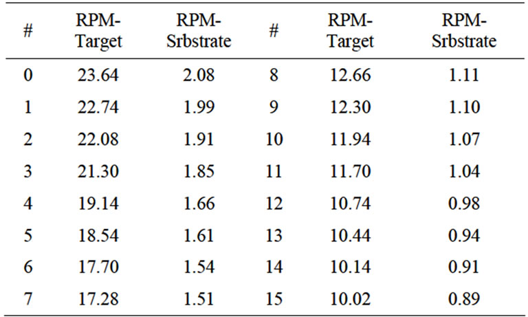
Table 1. Table type styles (table caption is indispensable).
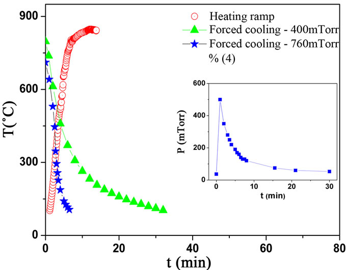
Figure 6. Substrate temperature vs time. Inset: chamber pressure during the heating ramp.
are shown in Figure 6. The forced cooling arises from a gas flow over the film surface, cooling down at greater rates. Also the system allows controlling that the rate of cooling combining its action whit the substrate heater current.
3.3. Film Characterization
The structure of target, film and substrate characterization was performed by XRD. The spectra were obtained in way with a speed of 0.004 [2q (/s)], step 0.020 [2q] and time by step of 5 s. Figure 7 shows XRD spectra corresponding to target, film and substrate. It is observed that film pattern have not parallel peaks to those corresponding to substrate. It also exhibits a preferential growth of (006) barium hexaferrite planes and the existence of diffraction peaks (107), (114) and (203) indicates the nearly random orientation of the c-axis. Room temperature hysteresis loops of the film, measured by Vibrating Sample Magnetometer (VSM) with a maximum field of 1.5 T are shown in Figure 8, after subtraction of the diamagnetic background from sapphire substrate.
For the measurement, different directions among the applied external field and the surface of the film were considered, in-plane and normal to the plane. The loops show that both directions are hard directions as expected from X-ray data.
Magnitudes corresponding to intrinsic coercivity, sat- uration and remanent magnetization of the film are listed in Table 2. The film intrinsic coercivity is higher than the corresponding one for bulk BaFe12O19 (≈4000 Oe), and the hysteresis squareness (Sq = Mr/Ms) is signifycantly greater than those reported by Zhang et al. for barium ferrite films with in-plane orientation deposited over silicon substrate [24].
 (1)
(1)
Note that the equation is centered. Be sure that the surface image taken by a Atomic Force Microscope Agilent 5500 AFM System, in Non-contact (AAC) mode in air is shown in Figure 9. The AFM image shows nearly in plane alignment of the easy axes. Barium ferrite normally has fast growth in ab-plane and slow growth in c-axis direction. The caxis is thus along the short in plane direction of the grains. Similar results were obtained for barium-ferrite thin films deposited by rf diode sputtering onto oxidized silicon substrate [25].
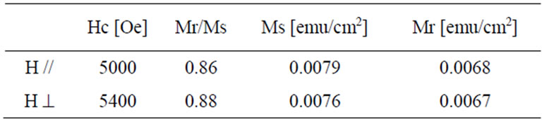
Table 2. Intrinsic coercivity, saturation, magnetization and remanence for applied external field, parallel and perpendicular.
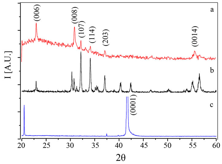
Figure 7. Pattern of XRD of (a) film (b) target, and (c) used substrate.
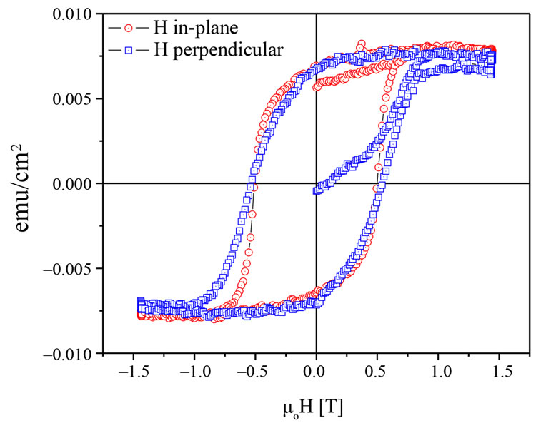
Figure 8. Hysteresis curves with external field direction applied parallel or perpendicular to surface’s.
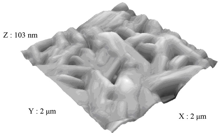
Figure 9. AFM image of film. Courtesy of Agilent Technologies Company in coordination with authorized distributor Analytical Technologies S. A.
The topographic analysis shows a roughness of 13.3 nm RMS (substrate roughness < 10 Å), peak altitude of 103 nm, depth of “well” 64 nm, and 9.87 nm of arithmetical medium altitude.
4. Conclusions
An economics complete system for deposits by PLD was built. The system allows to make thin film deposits at different substrate temperatures into a controlled atmosphere. Also it is possible to control the time of cooling of the film, allowing changing the properties of the deposited films. As an example, the magnetic behavior of barium ferrite film deposited on sapphire substrate was evaluated. XRD corroborated that the deposited material crystallized as Ba hexaferrite phase with an unusual preferential grown direction and AFM image analysis shows a rough deposit surface. The analyzed deposited film showed interesting characteristics regarding to their magnetic properties, like the significant increase of Mr/Ms ratio. It can be emphasized that the developed system presents the necessary characteristics to obtain single or multi layers films.
Also the PLD system include a new and original part, the ring nozzle, that allow control both, cooling rate and reactive local atmosphere of the substrate. Control of these parameters is very important to obtain some materials with specials properties.
5. Acknowledgements
This work was partially supported by CONICET, SECyTUNC and FONCYT, Argentina. The AFM image was facilitated by the Agilent Technologies Company.
REFERENCES
- M. S. Yuan, H. L. Glass and L. R. Adkins, “Epitaxial Barium Hexaferrite on Sapphire by Sputter Deposition,” Applied Physics Letters, Vol. 53, No. 4, 1988, pp. 340-341.
- B. Y. Wong, X. Sui, D. E. Laughlin and M. H. Kryder, “Microstructural Investigations of Barium Ferrite Longitudinal Thin-Film Media,” Journal of Applied Physics, Vol. 75, No. 10, 1994, pp. 5966-5968. doi:10.1063/1.355527
- C. Surig, K. A. Hempel and D. Bonnenberg, “Formation and Microwave Absorption of Barium and Strontium Ferrite Prepared by Sol-Gel Technique,” Applied Physics Letters, Vol. 63, No. 20, 1993, pp. 2836-2838. doi:10.1063/1.110303
- J. D. Adam, S. V. Krishnaswamy, S. H. Talisa and K. C. Yoo, “Thin-Film Ferrites for Microwave and Millimeter-Wave Applications,” Journal of Magnetism and Magnetic Materials, Vol. 83, No. 1-3, 1990, pp. 419-424. doi:10.1016/0304-8853(90)90570-G
- J. J. Coleman, “Metalorganic Chemical Vapor Deposition for Optoelectronic Devices,” Proceedings of the IEEE, Vol. 85, No. 11, 1997, pp. 1715-1729. doi:10.1109/5.649647
- T. Frey, C. C. Chi, C. C. Tsuei, T. Shaw and F. Bozso, “Effect of Atomic Oxygen on the Initial Growth Mode in Thin Epitaxial Cuprate Films,” Physical Review B, Vol. 49, No. 5, 1994, pp. 3483-3491. doi:10.1103/PhysRevB.49.3483
- P. R. Wilmott and J. R. Huber, “Pulsed Laser Vaporization and Deposition,” Reviews of Modern Physics, Vol. 72, No. 1, 2000, pp. 315-328. doi:10.1103/RevModPhys.72.315
- S. Metev, “Pulsed Laser Deposition of Thin Films,” In: D. Chrisey and G. Hubler, Eds., Process Characteristics and Film Properties in Pulsed Laser Plasma Deposition, Wiley, New York, 1994, p. 255.
- K. H. Wu, J. Y. Juang., C. L. Lee, T. C, Lai, T. M. Uen, Y. S. Gou, S. L. Tu, S. J. Yang and S. E. Hsu, “Optimization of Depositier Ablation Plumes Measured by Fast Intensified Charge Coupled Device Photographs,” Nuclear Instruments and Methods in Physics, Vol. 116, No. 3-4, 1996, pp. 257-261.
- D. Baüerle, “Laser Processing and Chemistry,” 3rd Edition, Springer, Berlin, 2000.
- S. Fähler, M. Störmer and H. U. Krebs, “Origin and Avoidance of Droplets during Laser Ablation of Metals,” Applied Surface Science, Vol. 109-110, 1997, pp. 433-436. doi:10.1016/S0169-4332(96)00782-9
- M. I. Oliva, F. A. Soria1, C. I. Zandalazini, C. A. Rinaldi and J. C. Ferrero, “Spectroscopic Study of the Pulsed Laser Ablation on Ba/Sr Ferrites,” Anales Asosciación Física Argentina, Vol. 19, 2007, p. 79.
- T. García, P. Bartolo-Pérez, E. de Posada, J. L. Peña and M. Villagrán-Muniz, “Studies of Pulsed Laser Deposition Processes of BaTiO3 Thin Films,” Surface and Coatings Technology, Vol. 201, No. 6, 2006, pp. 3621-3624. doi:10.1016/j.surfcoat.2006.08.117
- C. H. Lei, “The Growth of BaTiO3 Films on (001) MgAl2O4 Substrates by Pulsed Laser Deposition Technique,” Thin Solid Films, Vol. 515, No. 4, 2006, pp. 1701-1707. doi:10.1016/j.tsf.2006.06.006
- C. Viespe, I. Nicolae, C. Sima, C. Grigoritu and R. Medianu, “ITO Thin Films Deposited by Advanced Pulsed Laser Deposition,” Thin Solid Films, Vol. 515, No. 24, 2007, pp. 8771-8775. doi:10.1016/j.tsf.2007.03.167
- A. Husmann, M. Mertin, T. Klotzbücher and E. W. Kreutz, “Deposition of BaTiO3 Thin Films by a Hybrid DC-Field Enhanced PLD-Process,” Applied Surface Science,Vol. 109-110, 1997, pp. 293-298. doi:10.1016/S0169-4332(96)00624-1
- P. Vase, Y. Q. Shen, T. Holst, M. Hagensen and T. Freltoft, “Substrate Heater for Large Area YBa2Cu3Ox Films Growth without Electrical Feedthroughs,” Physica C: Superconductivity, Vol. 235-240, No. 1, 1994, pp. 641-642.
- K. H. Wu, C. L. Lee, J. Y. Juang, T. M. Uen and Y. S. Gou, “In situ Growth of Y1Ba2Cu307-8 Superconducting Thin Films Using a Pulsed Neodymium: Yttrium Aluminum Garnet Laser with CO2 Laser Heated Substrates,” Applied Physics Letters, Vol. 58, No. 10, 1991, pp. 1089-1091. doi:10.1063/1.104380
- J. C. Clark, J. P. Maria, K. J. Hubbard and D. G. Schlom, “An Oxygen-Compatible Radiant Substrate Heater for Thin Film Growth at Substrate Temperatures up to 1050˚C,” Review of Scientific Instruments, Vol. 68, No. 6, 1997, pp. 2538-2541. doi:10.1063/1.1148156
- X. Y. Zhang, C. K. Ong, S. Y. Xu and H. C. Fang, “Observation of Growth Morphology in Pulsed-Laser Deposited Barium Ferrite Thin Films,” Applied Surface Science, Vol. 143, 1999, pp. 323-327. doi:10.1016/S0169-4332(99)00100-2
- R. K. Singh, L. Ganapathi, P. Tiwari and J. Narayan, “Effect of Processing Geometry in Oxygen Incorporation and in situ Formation of YBa2Cu3O7 Superconducting Thin Films by Pulsed Laser Evaporation Technique,” Applied Physics Letters, Vol. 55, No. 22, 1989, pp. 2351-2353. doi:10.1063/1.102364
- X. Y. Zhang, C. K. Ong, S. Y. Xu and Z. Yang, “Barium Ferrite Films with In-Plane Orientation Grown on Silicon by Pulsed Laser Deposition,” Journal of Magnetism and Magnetic Materials, Vol. 190, No. 3, 1998, pp. 171-175. doi:10.1016/S0304-8853(98)00303-5
- Y. Chen and M. H. Kryder, “Temperature Dependent Magnetic Properties of Barium-Ferrite Thin-Film Recording Media,” IEEE Transactions on Magnetics, Vol. 34, No. 3, 1998, pp. 729-742. doi:10.1109/20.668078
NOTES
*Corresponding author.