Modern Mechanical Engineering
Vol. 3 No. 2A (2013) , Article ID: 33474 , 8 pages DOI:10.4236/mme.2013.32A002
Application and Analysis of Force Control Strategies to Deburring and Grinding
Institute of Production Systems, TU Dortmund University, Dortmund, Germany
Email: frank.domroes@tu-dortmund.de, carsten.krewet@tu-dortmund.de, bernd.kuhlenkoetter@tu-dortmund.de
Copyright © 2013 Frank Domroes et al. This is an open access article distributed under the Creative Commons Attribution License, which permits unrestricted use, distribution, and reproduction in any medium, provided the original work is properly cited.
Received April 30, 2013; revised May 31, 2013; accepted June 8, 2013
Keywords: Robot Machining; Deburring; Grinding; Force Control Strategies
ABSTRACT
This paper aims to give an insight into the development and evaluation of force controlled machining processes with a commercially available setup. We will focus on a deburring and a grinding scenario, representing the major applications in today’s robot machining. Whereas the deburring use-case implements a force dependent feed-rate control, the grinding use-case implements an orthogonal force (pressure) control. Both strategies will be evaluated and the influence of general machining and robot specific parameters will be discussed.
1. Introduction
Industrial robots are more and more used for machining tasks. The main reason for this is that the investment costs that are required to purchase these robots are much smaller compared to the costs for purchasing a CNC machining center. Other advantages are the relatively small footprint that is needed to build up, in relation to the large work space of the robot and the fact that the robot can easily carry out preceding and subsequent handling processes. Thus, it is not necessary to implement additional devices to load and unload the machining centers.
Of course, the comparison is not complete without considering the robot’s limitations, e.g. a significantly lower stiffness compared to a machining center. This lack of rigidity, among other, has negative effects on the accuracy of the robot during the machining process [1]. On the other hand, recently developed force control systems for industrial robots have proven very good performance, e.g. high sampling rate and low input-output latency, in a range of different machining applications [2].
2. Related Work
To face the occurring problems during machining robot manufacturers have optimized some of their robot kinematics for the use in machining processes. The manufacturer ABB Ltd. has developed a particularly stiffened robot that is explicitly marketed for “pre-machining”: the IRB 6660-208/1.9 [3]. The manufacturer Stäubli is following a different approach with its RX170 hsm. This robot has a spindle directly connected to its fifth axis, in order to achieve an improved rigidity [4].
In addition to mechanical aspects, process control technology is an important factor. Each robot manufacturer uses a different programming language for the definition of motion commands. This means that the data generated by CAM systems can’t be used directly with a robot, but must be translated into the native robot language. Some offline programming systems for robots are able to import NC programs and then create appropriate programs for the robot.
With the software option KUKA, CNC the manufacturer KUKA integrated a complete CNC control into the robot controller. Therefore the NC programs do not need to be converted into robot programs but run directly on the CNC control, which also results in a different motion behavior of the robot [5].
A different approach has been presented from ABB Robotics with the application package “Force Control for Machining” [6]: A 6D force torque sensor at the robots flange was integrated into the control loop. This makes it possible to apply a defined contact force between the robot and its environment during the movement. This functionality is particularly used in grinding and polishing processes [7].
Many university research efforts aim to increase the accuracy of robot machining processes. The Institute PTW at TU Darmstadt is analyzing the interactions between the robot structure and the executed milling process to develop a coupled simulation. Core component of the simulation is an offline correction in order to minimize the deviations of the trajectories that are caused by the process [8,9].
In the EU-funded project COMET (plug-and-produce components and methods for adaptive control of Industrial robots enabling cost effective, high precision manufacturing in factories of the future) an international consortium of industrial companies and research institutions are working on the development of components and methods for high-precision robotic machining. The approach of this project is to capture the inaccuracies of the industrial robot online and directly compensate these inaccuracies by applying an offset to the clamping system of the work piece using an additional high precision kinematic [10].
Additionally to the efforts on improved robot accuracy, force control strategies were developed for machining processes which are less geometrical constrained. In [11] a force dependent feed-rate control, among other, was presented, who shifts the robot speed in discrete steps depending on the measured force. If even at reduced speed the interaction forces exceed the defined range, a recover routine can avoid tool breakage. This function is very capable and we will later demonstrate how this enables online adaption of deburring paths.
Aside from the possibilities in process control, force control in robotics is used to reduce teaching effort. As teaching the paths on the geometry of e.g. casted work pieces in general can be very time consuming. Therefore for work pieces which vary in shape or size different approaches have been presented in literature to reduce the teaching effort.
Zhang et al. presented a force and vision sensor based deburring approach where the robot follows an afore marked path and thereby accomplished a time reduction compared to manual teaching from 8 to 10 weeks to 1 hour [12]. Solvang et al. took the expertise of the worker into account to define a path on a 2D camera image of the real work piece and map this input to a CADmodel in an offline programming environment to create the robot paths [13].
Although these methods allow a significant improvement to conventional teaching methods regarding both time savings and accuracy gain, they do fit exactly to the requirements of small and medium enterprises (SME’s). As these companies mostly rely on small batch production, a large variety of work pieces has to be treated by the automated system with as little teaching effort and user interaction as possible. At the same time systems have to be smart and reliable. To keep the investment on an acceptable level, new approaches should focus on inherent flexibility before the integration of more sensor technology is considered.
3. Deburring of Water Pump Impellers
3.1. Background
In a typical deburring application the aim is to remove primary burr along the edges of the work piece, e.g. from casting or machining processes, with a rotary cutting tool mounted on a spindle-drive. Additionally, it is often desired to break the edge with a 45˚ angle, so that the worker will not be harmed during handling and/or assembly.
The application considered here is a deburring task of water pump impellers from various shapes and sizes. The impellers are created from high strength bronze in a foundry process with various subsequent stages of traditional CNC machining. Burr appears mostly along impeller blade edges and, considering the measurable influence of edge shape on pump efficiency, has to be removed with care. This job is traditionally done by hand labor aligned with high physical demands on the worker in a rough environment.
The experimental system is built around an industrial robot (ABB IRB 4400) with 60 kg maximum payload and equipped with a force control application package. Attached to the robot’s flange are a force torque sensor (ATI Omega 160) and a 3-finger-gripper (SOMMER AUTOMATIC GD316) to unload the impellers directly from a CNC machine. An electric spindle drive mounted on a table can provide speeds between 5000 and 36,000 rpm at a maximum output power of 8 kW. The actual tool for deburring is a cone shaped hard-metal cutter.
3.2. Path Generation and Adaption
What makes the impeller deburring process especially suited for the development of a force controlled machining strategy is the fact, that precise 3D geometry information usually provided by CAD-files is not available for the majority of impeller types. Therefore the sole use of geometrical path planning is simple not an option. Instead a generalized task description was derived and deburring trajectories are corrected online based on contact force information. This should theoretically allow handling a high work piece variety without high offline programming and teaching effort as well as provide better and more constant process quality compared to manual deburring.
The edges to deburr on the impeller are marked in Figure 1. A comparison among the possible impellers showed that the path consists of 3 sections and can be described as a lower circular path between a start point (1) and the next impellers blade (2) and an upper circular path, from start point (3) with identical diameter but with
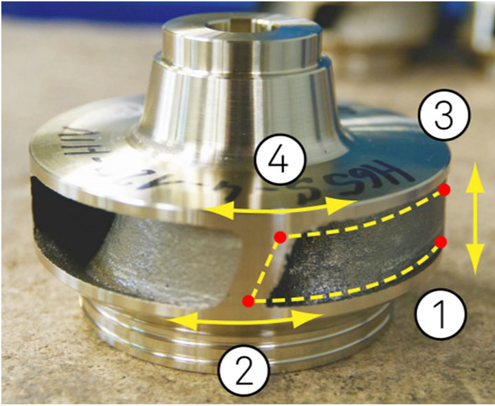
Figure 1. Impeller with marked deburring path and directions of path adaption.
a different endpoint (4) due to the inclination of the blade. The third section is defined by the linear connection of the two endpoints (2), (4). Among the parameters available for every impeller are diameter, number of blades and height. No a-priori information about edge positions, blade position and blade angle is available.
A robot equipped with force control can offer several possibilities for the detection of the missing information and the execution of the general task fitted to the specific impeller geometry: Two different searching methods were developed: one method ahead of deburring and one right in the course of a deburring path.
The first method is a linear sensing movement which represents a relatively simple way of finding a surface and updating a robot pose. Only the searching direction is force controlled in which the robot will move according to the defined reference force. It will stop and move back immediately when tool and work piece get into contact. The benefit from this method is that any error or change in tool or work object (tool wear or tolerances) will be included in the measurement and therefore compensated.
To ensure that neither tool nor work piece are damaged the robot control system has to be highly responsive. A low reference force of 15 N is used, but the main factor here is that the robot’s force control system allows to define (position and/or force) conditions on axis controller level. During searching movement the force condition is checked in constant 4 ms cycles rather than 25 to 50 ms on high level control and therefore high force peaks are avoided. The accuracy of the searching movement depends on the work piece surface, especially with harsh casting parts. To perform a search the robot moves the impeller until in contact to the either rotating or static deburring tool mounted on the spindle drive. A comparison of 4 different searching configurations and the acquired accuracy is presented in the results section.
Based on the knowledge about the edge position in axial direction and the diameter, a circular path for deburring can be calculated with an estimated endpoint.
However the true end point is unknown and an inaccurate path would cause either incomplete removal of burr or damage due to collision.
For this purpose the second searching method was developed, using the feed-rate control. The robot move towards the estimated endpoint at a relatively high speed as long as measured force stay below a user defined value (e.g. 40 N). When the amount of burr increases or the blade edge is reached, process force will suddenly rise and the feed rate will be automatically lowered. At reduced speed the robot will move on as long as the forces don’t exceed the specified limit even at minimum feed rate. This allows control over the amount of material to be removed from the impeller edges (compare endpoints in Figure 1).
When the force limit is reached at minimum feed rate, a recover routine is triggered, which will stop the circular movement, store the current position and let the robot move on to the next instruction in program. This is performed twice for upper and lower edges and lastly between the former stored end positions.
With just these two methods, we can provide automated deburring for a wide range of different impeller models with a minimum of a-priori knowledge. Basically the only individual parameters used for the internal calculation of path and search starting point are diameter and height which the robotic system can access through a “.txt” file or similar. The generic path (Figure 1, dashed line) has to be defined just once and then it is automatically “shrinked” or “stretched” based on the sensed contact information before an in course of the deburring.
3.3. Results
The forces in movement direction of the tool as well as signals for speed change are shown in Figure 2. In the first section the robot is deburring the horizontal edge of the impeller at 10 mm/s with relatively low contact forces. After 4 seconds the vertical edge is reached and force rises due to the much higher amount of material to be removed. The feed-rate controls aimed to keep the material removal rate at high level as long as the measured force remains below a user defined level [11].
In the presented case, when the vertical edge was reached, the measured force exceeded the reference of 40 N and the feed-rate control kicked in. The robots speed was reduced stepwise (4 steps are used in this case) until lowest level (5%). At this reduced speed, the cutting continued about 4 seconds and the force rose slowly. At 130 % of reference the recover function was triggered (speed ratioshifts to zero in Figure 2) and the robot was stopped and moved out of the impeller.
From the graph it becomes also clear, that the force signals are increasingly affected by shatter when cutting
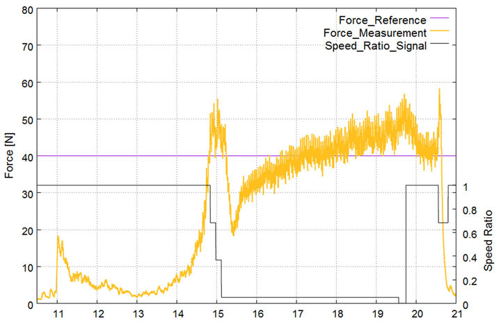
Figure 2. Forces and speed level during deburring.
deeper into material. Controlling this shatter is among the most challenging aspects in machining, as it affects surface quality and it can damage the robot. In our case this tendency was not yet correct active. To achieve higher stability of deburring results the force measurement are internally low pass filtered with 5 Hz.
Obviously, with the right combination of force control parameters the feed rate control allows the robot to keep forces under reference level even with sudden contacts and increasing depth of cut. The fast reaction eliminates high stress on the tool and the robot. From the force trend after initial contact it can also be concluded, that it’s possible to control the amount of material to be removed by adjusting the reference force. This is important to the customer who naturally wishes not only to remove burr but also to control chamfer size.
As explained in the path generation section, the deburring paths rely on the sensed contact points during automated teaching. Therefore the repeatability of the searching procedure is of high interest and was examined during tests. We analyzed the results of a total amount of 80 edge touching actions in four different configurations: Touching the vertical impeller edge either from below or from above and with a rotating or a static tool. Tool rotation should reduce possible damage of the cutter but it is also of interest whether this can equalize the effect of burr along the touched edge on measurement quality.
The positions stored by the robot are shown in Figure 3. It is important to notice, that the positions are calculated from the robots internal resolver values for each axis, and therefore don’t represent necessarily the absolute position of the mechanical end-effector. We will repeat testing with an external optical measurement system in future. So far, interpretation of captured data focuses on the repeatability of force triggered positions and disturbances from spindle rotation and gravity.
With the static tool the distance from starting point to the lower edge was measured after 20 repetitions as 4.5068 ± 0.0105 mm in z-axis (searching direction) and 0.0157 ± 0.0031 mm in x-axis. For the lower edge distances were measured as 4.4918 ± 0.0212 mm and 0.0140 ± 0.0028 mm for z and x-axis. Upper and lower search results show a similar perpendicular deviation to the searching direction.
The situation with a running spindle is more complex as with every touching the test constrains change. Material on the edge is removed and therefore the z-distance and standard deviation of contact points naturally increases. But still two effects can be derived from the data: Contact points show a significant drift in x-axis of 0.0153 ± 0.0054 mm and 0.0428 ± 0.0028 mm, measured in relation to starting position. In z-axis corresponding values are 4.9238 ± 0.1345 mm for lower and 5.5134 ± 0.2294 mm for upper edge respectively. This can be identified as influence of the spindle, as the clockwise rotating tool pushes the work pieces sideways when in contact.
The second effect is visible when comparing the depth of cut during touching. Mean Values for upper (1.022 mm) and lower edge (0.417 mm) indicate that the depth more than doubles when touching against gravitation compared to touch in direction of gravity force.
3.4. Discussion
The performance found in the touching experiments is very good, especially for a rather large and heavy robot.
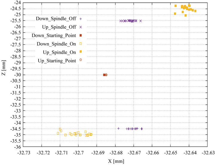
Figure 3. Contact points for different searching configurations.
It has to be considered though, that touching was realized always with equal robot arm configuration and with very limited movement of the primary robot axes. This is a common way of controlling position repeatability on a higher level than the manufacturer is stating in product data sheet.
The deviation perpendicular to the searching direction is marginally small compared to the standard repeatability values for a robot like this of about 0.1 mm.
Possible explanations for the drift in x-direction are errors during load identification and sensor calibration. The load on the sensor from gripper and work piece is around 20 kg and therefore rather large compared to the reference force during touching of just 15 N. But the influence of gravity might be just one factor among others here.
The test procedure shows that touching within one robot arm configuration and with limited searching range provides a reliable and accurate way of letting a robot learn its environment. The responsiveness of the control system meanwhile prevents that high forces exceed to the robot even than the upcoming contour in deburring is not known.
4. Grinding of Forming Tools
The goal of the subproject A6 in the Collaborative Research Centre 708 of the DFG (German Research Association) at the Institute of Production Systems (IPS) at TU Dortmund University is the development of a robot based grinding process to optimize the geometry and the surface properties of hard-coated surfaces.
The focus of this research project is the modeling of a robotic grinding process, a process-adapted simulationbased robot path planning and the use of a force controlled process execution. The aim of the project is to improve the robotic process execution through a holistic, systematic optimization of the process parameters of the grinding process, and the robot control algorithms, especially of those dealing with robotic force control, in order to meet the requirements according to dimensional accuracy and surface quality.
To verify the applicability of industrial robots in grinding processes with grinding tips, among other things, the influence of the robot system on the result of the machining process must be examined. One of the first steps is the derivation of a model for industrial robotic grinding with grinding tips, which describes the dependence of the removal rate of various process parameters (normal force, cutting speed, feed-rate, etc.). Such a model is intended to be used to predict the volume of the removed material and the shape of the product after machining.
A complete mathematical description of the grinding process is hardly possible, because all relevant factors, such as size and shape of each abrasive grain, can’t be determined accurately. As grinding is defined as a machining process with geometrically undefined cutting edges, the factors of a process model can only be defined statistically. Therefore, in the context of this project only an empirical process model for robotic grinding with grinding pins is been developed, which is based on the results of the experiments carried out in a pilot work cell. A first process model has been published in [14].
Another main goal of the project is the optimization of the control of the machining process using a force control system. Therefore the controller action and the influence of this action on the machining process have to be looked at. The first results of this research work will be presented in this paper. Furthermore it is necessary to look at the advantages and disadvantages of a force controlled versus a position controlled grinding process.
4.1. Experimental Setup
To perform the necessary modeling experiments and to analyze the robot behavior during the force controlled machining process, a pilot robot cell was set up. Figure 4 shows the setup and individual components.
As a part of the force control extension module a 6 axis force torque sensor is mounted between the robot flange and the electric spindle. The use of the force control option allows the execution of the machining process with a defined constant force. Thereby a uniform ablation along the machining path can be obtained.
The forcetorque sensor can capture and record the forces generated during the machining process. As tools, electroplated cBN grinding tips are used with a diameter of D = 12 mm with various grain sizes. The high-frequency electric spindle with a speed of up to 36,000 rpm provides high speeds (up to 20 m/s) during processing. Coated flat specimens with dimensions of 70 mm × 50 mm × 10 mm and layers applied with a minimum thickness of about 400 µm were used in the underlying test series.
4.2. Position-Controlled versus Force-Controlled Grinding Process
Since the robot system can be used with both control approaches, position-controlled and force-controlled, it should initially be considered which of these two approaches is more appropriate for the process of robotic based grinding with grinding tips.
Looking at the position controlled grinding process the infeed of the grinding paths is the primary control parameter of this process type (in contrast to the force controlled process type, where a defined contact force is the primary control variable). As the amount of the material that is removed in the present grinding application is very small (50 - 300 µm), the accuracy of the robot plays a crucial role. As a constant contact force is hard to be realized due to the lack of stiffness of the system, a deviation in the removal rate is occurring.
In order to compensate manufacturing inaccuracies that may occur, it may be necessary to scan the work piece surface before the machining process with a special
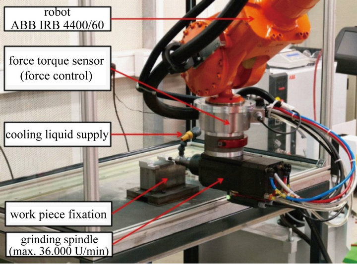
Figure 4. Experimental setup.
sensor or camera system and to adapt the robot paths appropriately, so that it is possible to obtain a material removal that is as constant as possible. Specially adapted strategies (gradual approximation) will also lead to useful machining results. In contrast to grinding in machining centers, where these strategies have been used long term, these strategies can also lead to problems in robotic machining due to the lower accuracy of the industrial robot. There is always the possibility of a too large increase of the infeed which leads to a large increase in the contact force, which can result in damages at the used grinding tool or the work piece that is machined.
In the force controlled grinding process it is theoretically possible to reach higher removal rates because the maximum removal is not limited by the infeed, and the contact pressure does not decrease during the machining process. A compensation of the position error in the direction of the contact force is also possible. In robotic based grinding the control of the contact force can be carried out by the force control of the robot. In this case, the goal is to establish a constant defined force between the tool and the surface of the work piece, independent of the feed movement.
The use of a modern force control system for industrial robots (e.g. the Force Control extension module from ABB Robotics [15,16]), which have a control cycle of 4 ms, allows the successful implementation of the force controlled process type in practice. Because of these advantages, the force controlled process type is preferred in the further work.
In order to get an impression of the correlation between the two process variants, in a first experiment the dependence of the normal contact force on the infeed between the work piece and the tool was determined. The grinding tips were moved over the surface of the work piece with different infeed values and different feed-rate using the robot. The contact force was measured by the forcetorque sensor. The experiments show a linear relationship between infeed and contact force [14].
4.3. Influence of the Force Deviation on the Deviation of the Removal Rate
In the following part of the paper we want to have a look on the influence of the force deviation on the deviation of the removal rate. Therefore several experiments have been executed in order to analyze if the contact force which is applied by the force-controlled robot system to the surface directly leads to a similar removal rate.
Using the same experimental setup as described in chapter 4.1 all process parameters have been fixed (constant infeed, vf = 15 mm/s, spindle speed: 16,000 rpm, width of the grinding tip: 10 mm, grain size: B126) with the exception of the contact force. Starting by a force value of 5 N, the contact force value has been increased up to 30 N. Furthermore a smooth increase of the force (22 N/s) along the grinding path has been implemented.
During the grinding process the contact force values have been recorded. Additional to the shape of the surface the work piece was measured before the grinding process and after the grinding process. For the measurements a coordinate measurement machine was used (Wenzel LH 54).
In Figure 5, the measured force progressions along the process time for some experiments of the experimental series are shown. All measured force progressions show the smooth increase of the forces. When the desired force value is reached, this force is maintained relatively constant until the end of the particular experiment.
The higher the desired force value is the later this constant phase is reached. It can also be seen that in the constant phase the values are also deviating around the adjusted force with amplitude of approx. ±1.5 N. For the lowest force (5 N) this value is higher (3 N).
A similar situation exists for the material removal along the robot path. In Figure 6, the force related removal progression of an experiment with a contact force of 22.5 N is shown. Clearly visible is the increase of the force at the beginning as well as the according progression in removal. Additionally, the removal at constant force is varying around a mean value. This deviation is not negligible and will be topic of further analysis.
5. Further Work
The results of our presented force controlled machining applications should allow the reader to compare the advantages and performance of the two presented force control strategies: force dependent feed-rate control and orthogonal force (pressure) control.
A force controlled robotic system of today’s state of the art can be successfully adapted to robotic deburring and grinding, which are major applications in robotic machining. But the demonstrated performance cannot be delivered out of the box. With the capabilities of robot force control the demands in programming are rising and so does the number of parameters which determine the robots behavior and process quality. Many tests under well defined circumstances in a test bed have to be performed to verify correct program execution and the op-
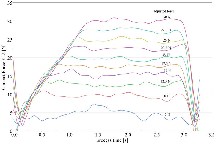
Figure 5. F_z progression of experimental series.
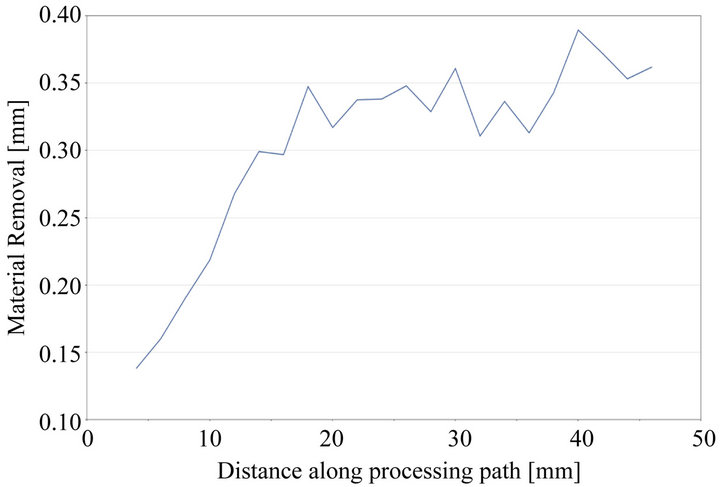
Figure 6. Material removal along the robot path at 22.5 N contact force.
timal parameters. The achieved results are limited to the inspected application or even one kind of work piece.
Based on our implemented use-cases we are able to investigate how the individual parameters, e.g. for the feed rate control, affect robot motion execution in contact with the environment as well as disturbances from the machining process itself. But instead of presenting another custom tailored solution, the aim is to present the acquired knowledge in an end-user friendly way, helping future operators on their way to optimal force control performance.
6. Acknowledgements
The authors gratefully acknowledge the financial support of the DFG (German Science Foundation) within the Collaborative Research Centre SFB 708, project A6.
Furthermore parts of the described work are funded in the project ProBeLa through the German Federal Ministry of Economics and Technology as part of the Central Innovation Programme SME (ZIM).
REFERENCES
- J. Pandremenos, C. Doukas, P. Stavropoulos and G. Chryssolouris, “Machining with Robots: A Critical Review,” Proceedings of DET2011 7th International Conference on Digital Enterprise Technology, Greece, September 2011, pp. 614-621.
- A. Robertsson, T. Olsson, R. Johansson, A. Blomdell, K. Nilsson, M. Haage, B. Lauwers and H. De Baerdemaeker, “Implementation of Industrial Robot Force Control Case Study: High Power Stub Grinding and Deburring,” 2006 IEEE/RSJ International Conference on Intelligent Robots and Systems, Beijing, 9-15 October 2006, pp. 2743-2748. doi:10.1109/IROS.2006.282000
- “IRB 6660 Industrial Robot,” ABB Robotics, Västerås, 2010.
- Stäubli International AG, “Robotertechnik für Maschinelle Bearbeitung,” 2008. http://www.staubli.com/en/robotics/6-axis-scara-industrial-robot/specialized-robot/high-speed-machining-robots/
- “KUKA.CNC for Maximum Robot Performance in Machining Processes,” KUKA Roboter GmbH, Gersthofen, 2011.
- “Application Manual Force Control for Machining, Revision: H,” ABB Robotics, Västerås, 2012.
- A. J. Wertz, “Robotic Grinding Using ABB’s Force Control Technology,” Benton Foundry Inc, Gettysburg, 2011. http://www.ductile.org/magazine/2011_2/alanwertz1.pdf
- T. Hemker, M. Friedmann, O. V. Stryk, M. Pischan, J. Bauer and E. Abele, “Prediction of the Tool Displacement for Robot Milling Applications Using Coupled Models of an Industrial Robot and Removal Simulation,” Proceedings of the CIRP 2nd International Conference Process Machine Interactions, Vancouver, 10-11 June 2010.
- J. Bauer, “Analyse der Wechselwirkungen Zwischen Industrieroboterstruktur und Fräsprozess,” TU Darmstadt, Institut für Produktionsmanagement, Technologie und Werkzeugmaschinen, Darmstadt, 2012.
- B. Olofsson, O. Sornmo, U. Schneider, A. Robertsson, A. Puzik and R. Johansson, “Modeling and Control of a Piezo-Actuated High-Dynamic Compensation Mechanism for Industrial Robots,” 2011 IEEE/RSJ International Conference on Intelligent Robots and Systems (IROS), San Francisco, 25-30 September 2011, pp. 4704-4709. doi:10.1109/iros.2011.6094846
- Z. Pan, “Intelligent Robotic Machining with Force Control,” Stevens Institute of Technology, 2005. http://books.google.de/books?id=FU5SNwAACAAJ
- H. Zhang, H. Chen, N. Xi, G. Zhang and J. He, “On-Line Path Generation for Robotic Deburring of Cast Aluminum Wheels,” Proceedings of the 2006 IEEE/RSJ International Conference on Intelligent Robots and Systems, Beijing, 9-15 October 2006, pp. 2400-2405. doi:10.1109/IROS.2006.281679
- B. Solvang, P. Korondi, G. Sziebig and N. Ando, “SAPIR: Supervised and Adaptive Programming of Industrial Robots,” The 11th International Conference on Intelligent Engineering Systems, Budapest, 29 June 2007-2 July 2007, pp. 281-286. doi:10.1109/ines.2007.4283712
- C. Krewet, M. Cabaravdic, A. Hypki and B. Kuhlenkötter, “Empirische Abtragsmodellierung für das Robotergestü- tzte Schleifen Thermisch Gespritzter Schichten,”2012.
- J. He, Z. Pan and H. Zhang, “Adaptive Force Control for Robotic Machining Process,” Proceedings of the 2007 American Control Conference, New York, 9-13 July 2007, pp. 1-6. doi:10.1109/ACC.2007.4282405
- J. Ge, F. Tan and H. Zhang, “Robot Machining: A Force-Control-Based Fast Programming Method,” 2008 IEEE Conference on Robotics, Automation and Mechatronics, Chengdu, 21-24 September 2008, pp. 730-735. doi:10.1109/RAMECH.2008.4681357