Modern Mechanical Engineering
Vol. 3 No. 2 (2013) , Article ID: 31636 , 8 pages DOI:10.4236/mme.2013.32010
The Study of Contact Pressure Analyses and Prediction of Dynamic Fatigue Life for Linear Guideways System
Department of Mechanical Engineering, Kun-Shan University, Tainan, Chinese Taipei
Email: hortl@mail.ksu.edu.tw
Copyright © 2013 Thin-Lin Horng. This is an open access article distributed under the Creative Commons Attribution License, which permits unrestricted use, distribution, and reproduction in any medium, provided the original work is properly cited.
Received April 2, 2013; revised April 30, 2013; accepted May 12, 2013
Keywords: Linear Roller Guideways; System Analysis; System Stress Analyses; Prediction of Fatigue Life
ABSTRACT
The application of the linear guideways is very extensive, such as automation equipment, heavy-duty carry equipment, heavy-cut machining tool, CNC grinding machine, large-scale planning machine and machining center with the demand of high rigidity and heavy load. By means of the study of contact behavior between the roller/guideway and roller/slider, roller type linear guideways can improve the machining accuracy. The goal of this paper is to construct the fatigue life model of the linear guideway, with the help of the contact mechanics of rollers. In beginning, the analyses of the rigidity of a single roller compressed between guideway and slider was conducted. Then, the normal contact pressure of linear guideways was obtained by using the superposition method, and verified by the FEM software (ANSYS workbench). Finally, the bearing life theory proposed by Lundberg and Palmgren was used to describe the contact fatigue life.
1. Introduction
The linear guideway type (LGT) recirculating rollers shown in Figure 1 has many advantages compared to ball guideways [1] and conventional sliding guides, such as flat ways and V-ways [2]. For instance, the ultimate loading of the roller guideway can be larger than that of a ball guideway, making the lubrication more efficient so that the abrasion of linear motion roller bearings is less than that of sliding guides. Linear motion roller bearings also have no stick slip. Linear motion roller guideways are widely used instead of ball guideways and sliding guides in heavy CNC machining centers, grinding machines, precision heavy-duty X-Y tables, and TFT-LCD transport systems [3]. In recent years, the speed of machines using linear motion rolling bearings has increased. Kasai et al. [4,5] found that carriages of preloaded recirculating linear roller bearings were moved periodically with the roller passing frequency due to roller circulation. Ye et al. [6] carried out a modal analysis for carriages of linear guideway type (LGT) recirculating linear roller bearings under stationary conditions and pointed out the existence of the rigid-body natural vibrations of the carriage. Schneider [7] developed a theory for the natural vibrations of an LGT recirculating linear ball bearing with a 45 degree contact angle. The study of prediction of dynamic fatigue life for linear guideways system, is not developed in the mentioned studies.
Horng [8-10] demonstrated stiffness equation and stress components for the circularly crowned roller compressed between two plates. Moreover, based on the previous results, Horng [11,12] developed stiffness expression, system stress distribution and vibration behavior for the linear guideway type recirculating rollers. In practice, the fatigue life of rollers composed in guideways plays a key role in the study of working life of linear guideways. Basically, two kinds of contact fatigue models have been developed over the past half century, i.e., crack initiation model and crack propagation model. Before 1980, almost all contact fatigue models had been developed by assuming the fatigue life was dominated by crack initiation.

Figure 1. Configuration of a linear guideway type (LGT) recirculating roller bearing [1].
The most famous model was the Lundberg-Palmgren model [13]. The second kind of models is developed by assuming the fatigue life was dominated by crack propagation. Most crack propagation models follow a Paris law [14], which was developed from tests of structural materials. The represented models are the Keer-Bryant model [15] and the Tallian model [16]. In contact fatigue life calculations, different critical stresses have been used. For example, Lundberg and Palmgren used maximum orthogonal shear stress in their model. Some researchers found cracks initiated at the depth where maximum shear stress occurs, which prompted them to use maximum shear stress to calculate the fatigue life [17]. Popinceanu [18] recommended the use of von Mises equivalent stress as the critical stress. Zhou [19] used octahedral shear stress to develop his new contact fatigue model. Cheng [20] found that the fatigue life of roller bearings under the pure rolling condition can be predicted by simply knowing the Hertzian contact pressure and the contact width, which avoids complicated calculation of the subsurface stresses. Previous models derived from Hertizan contact mechanics theory ignored the role played by the reliability of precious calculation in contact deformation and stresses. However, Palmgren did not have confidence in the ability of the Hertzian equations to accurately predict rolling bearing stresses. Palmgren states, “The calculation of deformation and stresses upon contact between the curved surfaces is based on a number of simplifying stipulations which will not yield very accurate approximation values. For line contact the limit of validity of the theory is exceeded whenever edge pressure occurs”. In other words, to calculate deformation and stresses accurately, especially edge stress occurred, it is essential to the prediction of fatigue.
In practice, the real experimental tests for the guideway were conducted to validate its quality. However, the real experimental tests require more cost and time-consuming. An alternative is to develop an analytical method that evaluates the dynamic fatigue life efficiently and easily. Moreover, the study of system stress analyses and prediction of dynamic fatigue life for linear guideway type (LGT), is not developed in the mentioned studies. In the present study, the analyses of deformation curve and the rigidity of guideway/slider for a single roller compressed between them were conducted. Then, the normal contact pressure of linear guideways was obtained by using the superposition method, and verified by the FEM software (ANSYS workbench). Finally, the bearing life theory proposed by Lundberg and Palmgren [21] is adopted to describe the contact fatigue life.
2. Determination of Normal Contact Pressure
Figure 1 shows the configuration of an LGT recirculating rollers. In order to analyze the normal contact pressure applied on rollers, the stiffness formula for a crowned roller compressed by a carriage and a profile rail is investigated. The model and dimensions are shown in Figure 2 and the profiles of a crowned roller are shown in Figure 3. The crowned roller is divided into three parts, two crowned parts and one cylindrical part, in which the primary axes of the roller system, denoted by x and y, are shown in Figure 3. The assumptions of this stiffness formula are: 1) friction is neglected because of the lubrication of the roller; 2) the depth effect of the carriage and rail can be simulated as equivalent depth; 3) the solution is obtained for the small-strain and linear elastic conditions; 4) rollers compressed between a carriage and profile rail are simulated as springs with parallel connection; 5) each discrete normal spring was modeled as a crowned roller compressed between two plates; 6) the normal force is applied to each contact point of the carriage and profile rail; 7) stick and slip effects of the contact zone between rollers and profile are neglected; 8) the preload effect of the linear guideway type (LGT) recirculating rollers is neglected; and 9) the stiffness of recirculating rollers in motion is similar to that of recirculating rollers in static.
According to the results by Horng [10], the normal contact pressure of the half-space within a small piece of
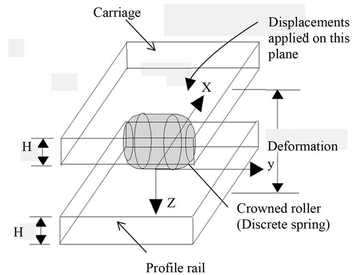
Figure 2. Model and dimensions of a crowned roller compressed between a carriage and profile rail, or one discrete spring.
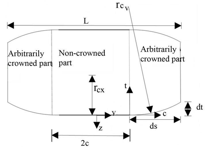
Figure 3. Geometry of arbitrarily crowned profiles.
distance interval along y coordinate demonstrated in Figure 2, is given by
 (1)
(1)
where E is Young’s modulus, v is Poisson’s ratio and  is the half length of the non-crowned part.
  and
and  are coefficients of the polynomial.
  is the principal value,
  is the total load and
  is the half width of the elliptical contact load.
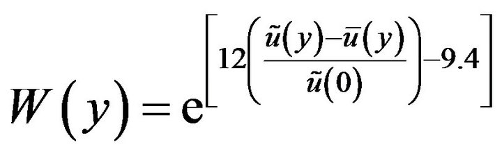
In order to overcome a defect of the half space theorem in which infinite plate thickness is set, a weighting method is introduced to find the normal pressure under a finite plate thickness. From the comparison between the displacement of finite plate thickness  and the displacement of the infinite plate thickness
 , it seems that the final normal pressure is equal to multiplying
 , which is calculated in half-space, by a weighting factor
 .
.  can be written in empirical form [10]
 (2)
(2)
Therefore, the final  measured from the center of contact to the edge can be expressed as:
 (3)
(3)
The distance  from the center of contact is set for the position which the edge stress occurred [10].
3. Lundberg-Palmgren Theory
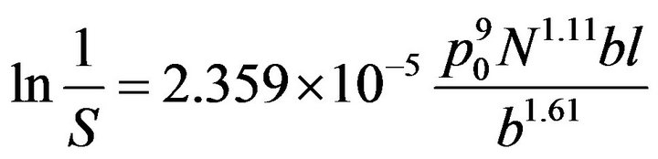
The genesis of the Lundberg-Palmgren theory for bearing life prediction traces back to the 1924 Palmgren paper [22]. However, because the 1924 paper was missing two elements, it did not allow for a comprehensive bearing life theory. The first missing element was the ability to calculate i he subsurface principal stresses and, hence, the shear stresses below the Hertzian contact of either a ball on a nonconforming race or a cylindrical roller on a race. The second missing element was a comprehensive life theory that would fit the observations of Palmgren. Palmgren, as will be discussed, distrusted Hertz theory and depended on a load-life reation for ball and roller bearings. In 1930, V. Thomasand and H. Hoersch [23] at the University of Illinois, Urbana, developed an analysis for determining subsurface principal stresses under Hertzian contact. In 1939, W. Weibull [24] published his theory of failure. Weibull was a contemporary of Palmgren and shared the results of his work with him. Palmgren, in concert with Lundberg, incorporated his previous work along with that of Weibull and what appears to be that of Thomas and Hoersch into what has become known as the Lundberg-Palmgren theory. Please note that Lundberg and Palmgren do not reference the work of Thomas and Hoersch in their paper. Lundberg and Palmgren, using the theoretical work of Weibull assumed that the logarithm of the reciprocal of the probability of survival  could be expressed as: a power function of maximum orthogonal shear stress
  (Gpa), fatigue life (Number of stress circle)
 , depth to the maximum orthogonal shear stress
 , and stressed volume
 . That is.
 (4)
(4)
where
 (5)
(5)
 is stress criteria exponent,
  is Weibull slope,
  is depth exponent,
  is depth of critical shear stress (mm),
  is the half Hertzian contact width (mm) and
  is the possible contact length (mm). Then,
 (6)
(6)
It is known from Lundberg and Palmgren theory that for the improved line contact condition three parameters , and
, and  are related by the following equation [24]:
 (7)
(7)
A search of the literature for a wide variety of materials and for nonrolling-element fatigue reveals that most stress criteria exponent  vary from 6 to 12. Zaretsky [25] assumes that the value of the stress criteria exponent
  and Weibull slope
 . Thus, depth exponent
  is equal to 2.61.
Cheng [20] found that the fatigue life of roller bearings under the pure rolling condition can be predicted by simply knowing the Hertzian contact pressure and the contact width, which avoids complicated calculation of the subsurface stresses. Under the conditions of non-frictional Hertzian line contact, maximum orthogonal shear stress  (Gpa) is related to the maximum Hertzian contact pressure
  through the following equation:
 (8)
(8)
Furthermore, the depths of the critical stresses under the condition of non frictional Hertzian line contact can be calculated as:
 (9)
(9)
Therefore, Equation (6) can be rewritten as:
 (10)
(10)
In beginning, the contact mechanical model was introduced to derive deformation curve on plate surface. Then, Modified Hertzian contact pressure and the contact width were calculated by using the relation between the plate deformation with finite and infinite depth. Due to the fatigue life of roller bearings under the pure rolling condition can be predicted by simply knowing the Hertzian contact pressure and the contact width which avoid complicated calculation of the subsurface stresses, the Lundberg-Palmgren life theory is introduced to predict the fatigue life for the arbitrarily crowned roller compressed between raceways
4. Results and Comparisons
Firstly, in order to verify the correctness of the theoretical solutions, a steel single roller compressed between two flat plates shown in Figure 2, was investigated. The comparison of maximum contact pressure of roller between the computation results using the above theoretical expressions and FEM software (ANSYS workbench), is conducted. In the CAD software the solid model is created, shown in Figure 4. The finite element model is simplified in order to compare with the theoretical results conveniently. Because of model symmetry, one-eighth of the model is taken to be simulated, shown in Figure 5. The dimension of the simplified LGT model of rollers is plotted in Figure 2, and Figure 3 as well as Table 1. After the model building completes, the mesh is created shown in Figure 6, the full model has 22803 elements, and 41,283 nodes. In the contact setting, the contact between the roller and the plate is set to nonlinear contact [26] shown in Figure 7. The type of contact is defined as frictionless, so as to closer to the actual situation. If the contact is set to be a linear contact, there will be a great gap between the theoretical solution and the simulation results. Because of the one-eighth model, the blue face in Figure 8 is set to be frictionless support in order to meet the symmetry of the set. Moreover, set the bottom face of the plate as fixed support, shown in Figure 9.
The displacement is applied on the roller shown in Figure 10. The displacement is set to be −0.01 mm, the direction is shown as the red arrow. The total deformation and equivalent strain are shown in Figures 11 and 12, respectively. The direction of the reaction force between

Figure 4. Simplified LGT model.
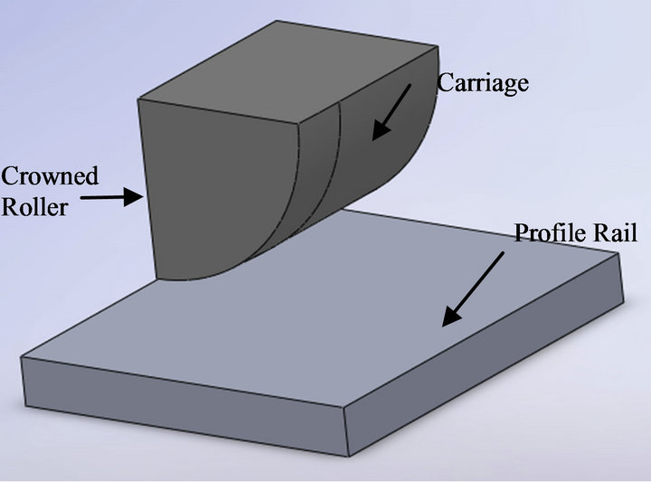
Figure 5. One-eighth of the simplified LGT model.
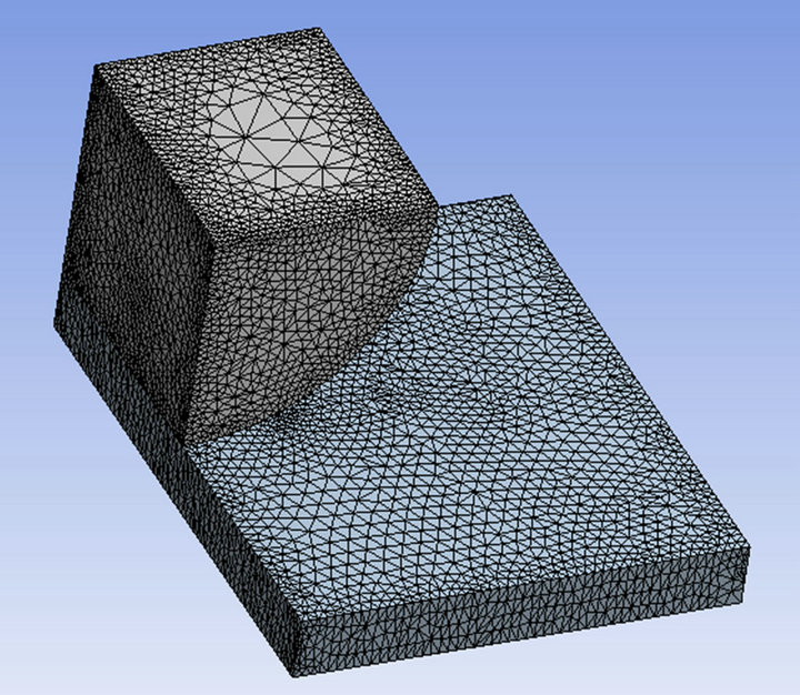
Figure 6. Finite element mesh.
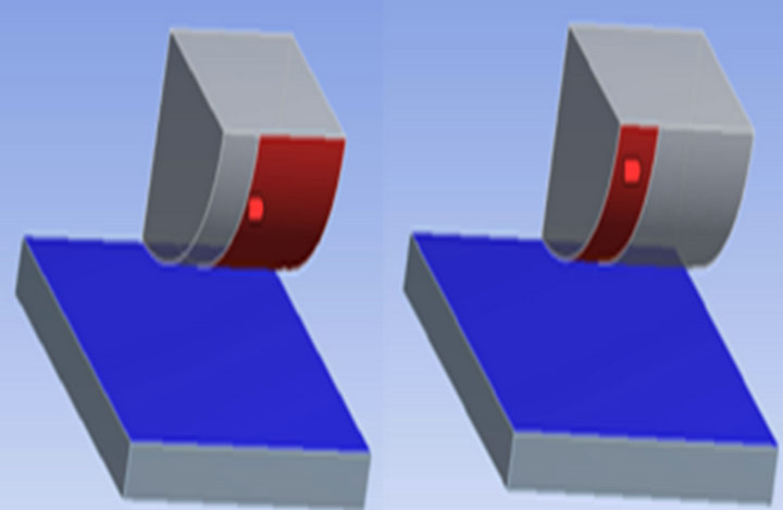
Figure 7. Contact setting.
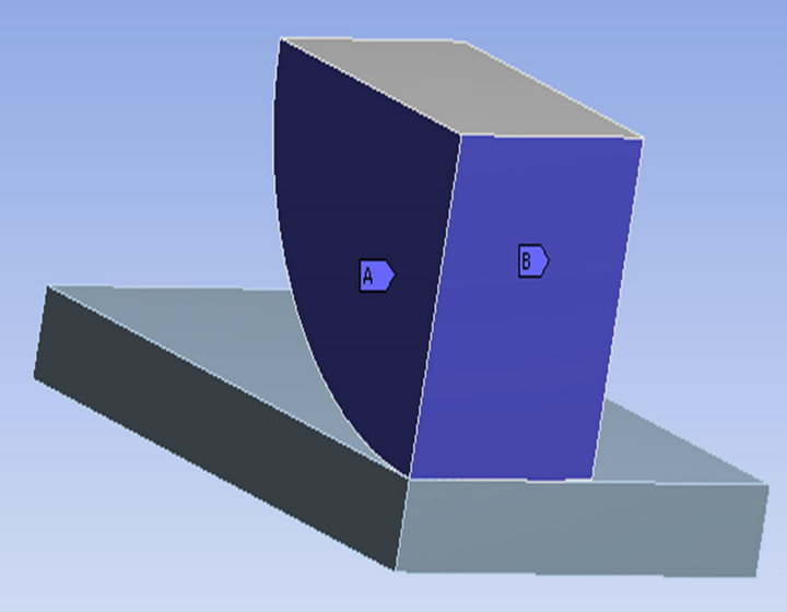
Figure 8. Frictionless support setting.
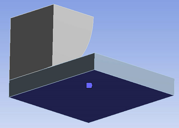
Figure 9. Fixed boundary conditions.
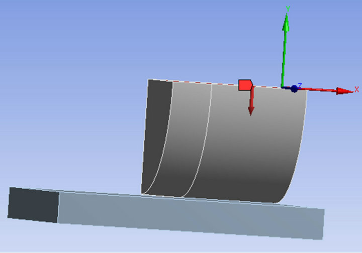
Figure 10. Displacement in the model.
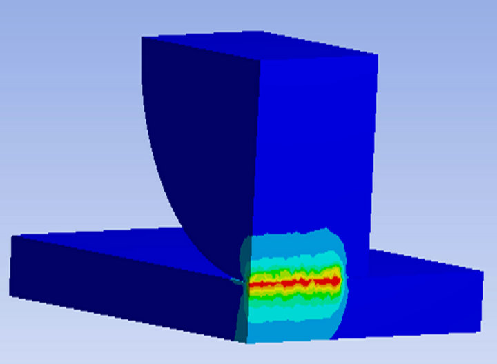
Figure 11. Total deformation.
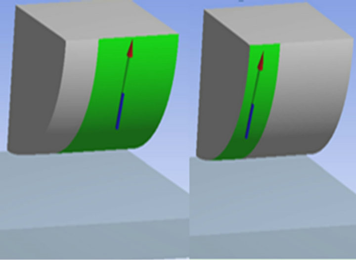
Figure 12. Equivalent strain.
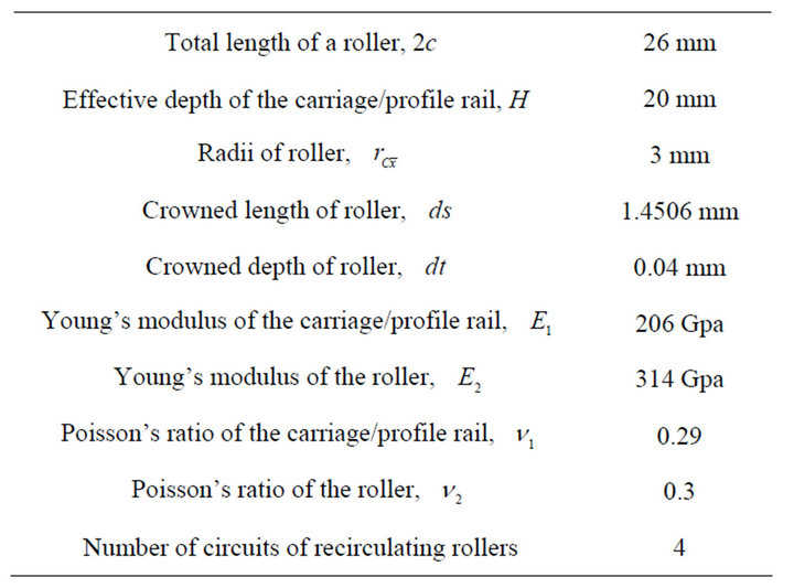
Table 1. Test linear bearing specifications.
the two contact bodies is shown in Figure 13, and the respective value is 1967.5 N and 224.17 N. The contact pressure on roller is 1131.7 Mpa, shown in Figure 14. The contact pressure on plate is 539.24 Mpa, shown in Figure 15. According to the instructions in the ANSYS Help [27], the actual contact stress should be the summation of the above two stress, so the maximum contact pressure is , and is very close to the theoretical results obtained by the Equation (10), denoted by 1583.33 Mpa. Therefore, the accuracy of theoretical expressions for the maximum contact pressure is acceptable.
Using the above maximum contact pressure expressions, we calculated the fatigue life of a carriage on LGT recirculating rollers. In the calculation of the fatigue life, the dimensions and material properties of LGT recirculating rollers shown in Table 1 were used. A steel roller compressed between two flat plates is shown in Figure 1, with the material properties being the same as mentioned previously. Firstly, we wish to find the maximum contact pressure  and the half Hertzian contact width
  at edge point. Then, the Lundberg-Palmgren life theory is introduced to predict the fatigue life for the arbitrarily crowned roller compressed between raceways. Probability of survival was plotted for fatigue life analyses. Figure 16 shows a comparison of calculated probability of survival for LGT recirculating rollers with circular crowned profiles subjected to the light displacement load. Figure 16 indicates that the effect of number of stress circle of LGT recirculating rollers to probability of survival, is not apparent subjected to the extremely light displacement load. Moreover, the probability of survival decrease with increasing applied displacements under the same number of stress circle. This is because of the larger contact pressure for the increasing displacement load. Figure 17 shows a comparison of calculated probability of survival for LGT recirculating rollers with circular crowned profiles subjected to the heavy displacement
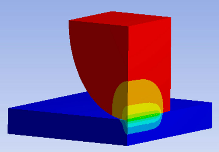
Figure 13. Reaction force.
load. Figure 17 indicates that the number of stress circle of LGT recirculating rollers significantly affects probability of survival subjected to the heavier displacement load, and the probability of survival decrease abruptly with the heavy displacement load. This is because the stress concentration effect becomes large near the edge when the heavy displacement load is applied to the LGT.
5. Conclusion
In this paper, linear guideway type (LGT) recirculating rollers were modeled as crowned rollers compressed between two plates. Then, an analytical solution of the the maximum contact pressure between roller and plates was
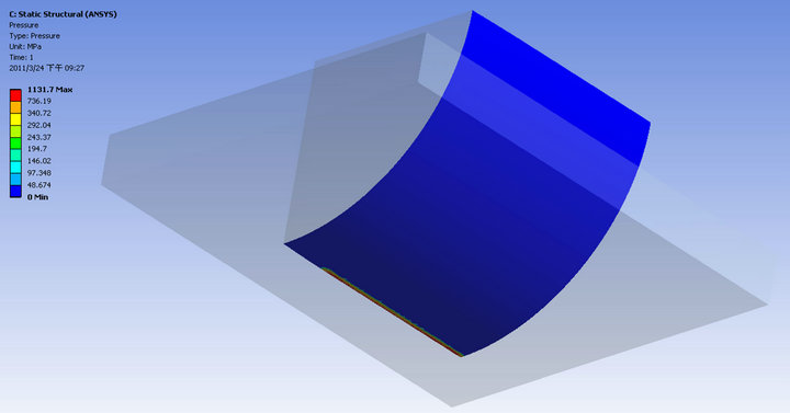
Figure 14. Contact pressure (Roller).
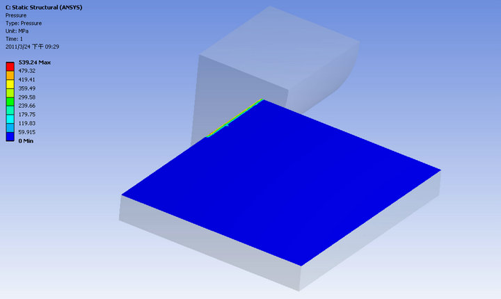
Figure 15. Contact pressure (Plate).
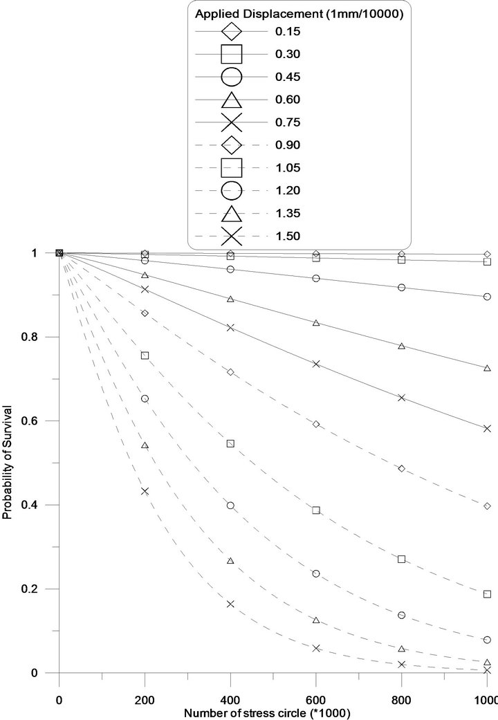
Figure 16. Comparison between the probability of survival subjected to light displacement load.
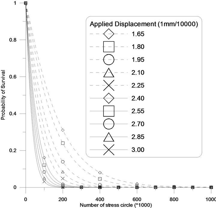
Figure 17. Comparison between the probability of survival subjected to heavy displacement load.
developed. From the comparison with FEM software (ANSYS workbench) result, the calculation model for normal contact pressure can be a reasonable estimate for a crowned roller being compressed between two plates. Finally, the system stress distribution of linear guideways will be obtained by using the superposition method, and the bearing life theory proposed by Lundberg and Palmgren is adopted to describe the contact fatigue life. The fatigue life prediction results reveal that the effect of number of stress circle of LGT recirculating rollers to probability of survival, is not apparent subjected to the extremely light displacement load, and the probability of survival decrease with increasing applied displacements under the same number of stress circle. This is because of the larger contact pressure for the increasing displacement load. Moreover, a number of stress circles of LGT recirculating rollers significantly affects the probability of survival subjected to the heavier displacement load, and the probability of survival decrease abruptly with the heavy displacement load. This is because the stress concentration effect becomes large near the edge when the heavy displacement load is applied to the LGT.
6. Acknowledgements
The authors would like to thank the National Science Council of the Republic of China in Taiwan for providing financial support for this study under grant NSC 99- 2221-E-168-021.
REFERENCES
- HIWIN, Ltd., “Technical Information of Linear Guideway,” HIWIN, Ltd., Taichung, 2007.
- H. Schmitz and G. G. Lyon, “Picking a Better Linear Bearing,” Machine Design, Vol. 66, No. 6, 1994, pp. 63- 65.
- NSK Ltd., “Precision Machine Parts,” NSK Ltd., Fujisawa City, 1989.
- S. Kasai, T. Tsukada and S. Kato, “Linear Guides for Machine Tools (in Japanese),” NSK Technical Journal, Vol. 647, 1987, pp. 39-50.
- S. Kasai, T. Tsukada and S. Kato, “Recent technical Trends of Linear Guides (in Japanese),” NSK Technical Journal, Vol. 649, 1988, pp. 27-36.
- J. Ye, N. Iijima, F. Tashiro, S. Hagiwara and S. Yamada, Vibration of Linear Motion Bearing (in Japanese),” Proceedings of Spring JSPE Meeting, 1988, pp. 199-200.
- M. Schneider, “Statisches und Dynamisches Verhalten Beim Einsatz, Liearer Schienfuhrungen auf WalzlagerBasis im Werkzeugmaschinenbau,” Carl Hanser Verlag, Munchen, Wien, 1991.
- T. L. Horng and S. H. Ju, “Stiffness of Arbitrarily Crowned Roller Compressed between Two Plates,” Journal of Engineering Tribology, Vol. 217, No. 5, 2003, pp. 375- 384.
- T. L. Horng, “Analyses of Stiffness in an Arbitrarily Crowned Roller Compressed between Raceways,” Journal of the Chinese Society of Mechanical Engineering, Vol. 24, No. 3, 2003, pp. 267-275.
- T. L. Horng, “Analyses of Stress Components for a Circular Crowned Roller Compressed Between Two Flat Plates,” Proceedings of the Institution of Mechanical Engineers Part Journal—Journal of Engineering Tribology, Vol. 221, No. 5, 2007, pp. 581-589. doi:10.1243/13506501JET263
- T. L. Horng, “Analytical Solution of the Stiffness Equation for Linear Guideway Type Recirculating Rollers with Arbitrarily Crowned Profiles,” Proceedings of the Institution of Mechanical Engineers Part C—Journal of Mechanical Engineering Science, Vol. 223, No. 6, 2009, pp. 1351-1358. doi:10.1243/09544062JMES1208
- T. L. Horng, “Analytical Solution of the Frequency Expressions for Rigid-body Natural Vibration of a Carriage on Linear Guideway Type Recirculating Rollers,” JSME International Journal—Journal of System Design and Dynamics, Vol. 3, No. 2, 2009, pp. 215-226.
- G. Lundberg and A. Palmgren, “Dynamic Capacity of Rolling Bearings,” Acta Polytechnica Scandinavica. Mechanical Engineering Series, Vol. 1, No. 3, 1947.
- P. Paris and F. Erdogan, “A Critical Analysis of Crack Propagation Laws,” ASME Journal of Basic Engineering, Vol. 85, No. 4, 1963, p. 528. doi:10.1115/1.3656900
- L. M. Keer and M. D. Bryant, “A Pitting Model for Rolling Contact Fatigue,” ASME Journal of Lubrication Technology, Vol. 105, No. 2, 1983 pp. 198-205. doi:10.1115/1.3254565
- T. E. Tallian, “Simplified Contact Fatigue Life Prediction Model. Part I: Review of Published Models. Part II: New Model,” ASME Journal of Tribology, Vol. 114, No. 2, 1992, pp. 207-220. doi:10.1115/1.2920875
- E. V. Zaretsky, R. J. Parker and W. J. Anderson, “A Study of Residual Stress Induced during Rolling,” ASME Journal of Lubrication Echnology, Vol. 91, No. 2, 1969, pp. 314-319. doi:10.1115/1.3554921
- N. G. Popinceanu, E. Diaconescu and S. Cretu, “Critical Stresses in Rolling Contact Fatigue,” Wear, Vol. 71, No. 3, 1981, pp. 265-282. doi:10.1016/0043-1648(81)90225-8
- R. S. Zhou, “Surface Topography and Fatigue Life of Rolling Contact Bearings,” Tribology Transactions, Vol. 36, No. 3, 1993, pp. 329-340.
- W. Cheng and S. Cheng Herbert, “Effect of Roller Profile on Cylindrical Roller Bearing Life Prediction,” ASME Journal of Tribology, Vol. 119, No. 2, 1997, pp. 233-240. doi:10.1115/1.2833163
- G. Lundberg and A. Palmgren, “Dynamic Capacity of Rolling Bearings,” Ada Polytechnica Mech. Eng. Series, Vol. 2, No. 4, 1952.
- A. Palmgren, “The Service Life of Ball Bearings,” Zeitschrift des Vereines Deutscher Ingenieure, Vol. 68, No. 14, 1924, pp. 339-341.
- V. A. Thomas and H. R. Hoersch, “Stresses Due to the Pressure of One Elastic Solid upon Another with Special Reference to Railroad Rails,” Technical Reports, University of Illinois, Engineering Experiment Station, Bulletin No. 212, 1930.
- W. Weibull, “A Statistical Theory of the Strength of Materials,” Royal Swedish Academy of Engineering Sciences, Vol. 151, No. 151, 1939.
- E. V. Zaretsky, J. V. Poplawski and S. M. Peters, “Comparison of Life Theories for Rolling-Element Bearings,” Tribology Transactions, Vol. 39, No. 2, 1996, pp. 237- 248.
- E. Madenci and I. Guve, “The Finite Element Method and Applications in Engineering Using Ansys,” The University of Arizona, Springer, Berlin, 2006.
- ANSYS, Inc., “ANSYS 12.1 HTML Online Documentation ANSYS Structural Nonlinearities Reference,” SAS IP, Inc., Canonsburg, 2009.