Open Journal of Metal
Vol.2 No.2(2012), Article ID:20294,6 pages DOI:10.4236/ojmetal.2012.22007
A Novel Technique for Determination of Flow Characteristics of Blast Furnace Slag
Department of Metallurgical and Materials Engineering, N.I.T. Rourkela, India
Email: ssarkar_2@rediffmail.com
Received May 1, 2012; revised June 4, 2012; accepted June 18, 2012
Keywords: Slag-Metal Reactions; Characteristic Temperatures; Hot Metal Quality; C/S Ratio; Short Slag
ABSTRACT
A study of flow characteristics of blast furnace slag helps determine its softening and flow (liquid-mobility) temperatures. The slag with a narrow difference between the two temperatures is termed a “Short Slag”. Its formation ensures higher rates of slag-metal reactions with the trickle of the slag soon after its formation exposing fresh mass for faster reactions, the trickling slag, creating fresh interfaces facilitating slag-metal exchanges. In the present work, a novel technique is adopted to determine the flow characteristics of blast furnace slag obtained from different industrial blast furnaces. It is seen that the results so obtained agree very closely with the values obtained from adopting conventional methods of determining the liquidus temperature using “slag atlas”. It is observed that under the range of compositions studied a high C/S ratio combined with a high MgO content in the slag is beneficial to the B.F. process as it renders a “short slag”.
1. Introduction
The ironmaking blast furnace is a complex high temperature counter current reactor in which iron bearing materials (ore, sinter/pellet) and coke are alternately charged along with a suitable flux to create a layered burden in the furnace. The iron bearing material layers start softening and melting in the cohesive zone under the influence of the fluxing agents at the prevailing temperature which greatly reduces the layer permeability that regulates the flow of materials (gas/solid) in the furnace. It is the zone in the furnace bound by softening of the iron bearing materials at the top and melting and flowing of the same at the bottom [1]. A high softening temperature coupled with a relatively low flow temperature would form a narrow cohesive zone lower down the furnace [2]. This would decrease the distance travelled by the liquid in the furnace there by decreasing the Silicon pick-up [3,4]. On the other hand the final slag, that trickles down the Bosh region to the Hearth in the furnace, should be a short slag that starts flowing as soon as it softens. Thus fusion behaviour is an important parameter to evaluate the effectiveness of the B.F. slag.
Fusion behaviour is described in terms of four characteristic temperatures [5]; IDT, the initial deformation temperature symbolising surface stickiness, important for movement of the material in the solid state; ST, symbolising plastic distortion, indicating start of plastic distortion; HT, the liquidus temperature, symbolising sluggish flow, playing a significant role in the aerodynamics of the furnace and heat and mass transfer; and FT, the flow temperature, symbolising liquid mobility.
The slag formed in the cohesive zone is the primary slag formed with FeO as the primary fluxing constituent; the solidus temperature, fusion temperature, solidus-fusion interval being significantly affected by FeO [6]. This slag is completely different from the final slag where the fluxing is primarily caused due to the presence of basic constituents like CaO or MgO. While it is not possible to obtain primary slag from the industrial blast furnace, it is always possible to prepare a synthetic slag in the laboratory resembling the primary slag and study its flow characteristics. We have kept this venture for future studies and the present study limits itself to the study of flow characteristics of the final slag as obtained from the industry. However, it must be noted that from the process point of view the final slag should be a “Short Slag”, a slag with a small difference between the ST and FT. Such a slag acquires liquid mobility and trickles down the furnace away from the site where it starts distorting plastically, as soon as possible. This action exposes fresh sites for further reaction and is supposedly responsible for enhanced slag-metal reaction rates, influencing the blast furnace operations and the quality of the metal.
The flow-characteristic of blast furnace slags is strongly influenced by the extent of reduction of iron oxide at low temperature (in the granular zone) besides being influenced by the composition, and the quality and the quantity of the gangue in the iron bearing materials. Ray et al. [7] have shown that the C/S (CaO/SiO2) and MgO content of the blast furnace slag greatly influence its softening-melting properties. Especially the MgO content in addition to C/S ratio is felt to be of such a great importance that Shen et al. [8] have actually proposed the addition of MgO through tuyere injection to make the MgO available later in the process. They claim that availability of MgO later in the process would result in small temperature range of cohesive zone resulting in better permeability of the bed which in turn would influence the coke consumption and quality of hot metal produced.
Keeping the above in mind, in addition to employing two different experimental techniques for measurement of the flow characteristics of industrial blast furnace slags and comparing the liquidus temperatures so obtained the present work also involves itself with analysis of the data on the basis of the chemical composition of the slag.
2. Experimental
There are two numbers of basic methods namely Pressure drop method and Slag atlas method for measuring melting characteristics of a burden or slag. The 1st method measures the width of the cohesive zone in a blast furnace directly by recording the softening (plastic distortion) and flow (liquid mobility) temperatures of the burden in terms of pressure drop.
An attempt is made [7] for testing softening and melting characteristics in the laboratory by simulating the changes occurring in a small volume of the iron bearing material in the vicinity of the cohesive zone. The changes undergone by the element as a result of the burden descent pertain to temperature, load, gas flow rate and composition. In order to achieve simulation in laboratory conditions the sample is subjected to a pre-programmed variation of temperature, composition of reducing gas and load variations as a function of time. The test consists of measuring pressure drop across the sample bed, height of the sample bed, inlet and exit gas composition/flow rates and the weight of the sample. From the data, the degree of iron oxide reduction (oxygen loss) and bed contraction are calculated and the data as obtained is presented in the form of a graph (Figure 1).
The interpretation of the graph (as reported) is as follows:
T1: Temperature in ˚C at which softening starts (Pressure drop reaches 1 kPa).
T2: Temperature in ˚C at which the sample bed stops contracting (Pressure drop returns to that at T1 i.e. 1 kPa).
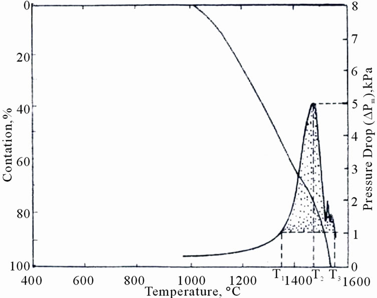
Figure 1. Softening melting test results and derived data.
However, this method suffers heavily on account of the following:
1) In this method, the dynamic nature of charge descent is not simulated.
2) The heat transfer and possible effects on the kinetics of iron oxide reduction are not accurately simulated.
3) This test method maintains constant gas flow rate throughout the test whereas in the actual furnace, the permeability of the charge is ever changing when iron burden layers soften during their descent.
4) This test is conducted at atmospheric pressure whereas the gas pressure inside the modern blast furnace maybe 2 to 4 times higher.
The second available method uses the predicted slag atlas for different major constituents of the slag (CaO, SiO2, Al2O3, and MgO) to determine the liquidus temperature of the slag of given composition [9]. One of the components is kept constant and the variations in other three constituents are simultaneously considered for estimation of the liquidus temperature. In the diagram below (Figure 2) the slag atlas for 20% Al2O3 is presented. The liquidus temperature of a slag with 20% Al2O3, 34.57% CaO, 6.51% MgO and 36.72% SiO2 is found to be 1300˚C (Point “L”, the intersection of line 1 and line 2 in the diagram parallel to the CaO-SiO2 line for MgO and SiO2-MgO line for CaO respectively).
In the present novel technique a hot stage microscope is used 5. The line diagram of the instrument is provided in Figure 3.
To measure the characteristic temperatures, a small cube (3 mm cube) of the sample is prepared from the powdered sample after adopting an appropriate method of sampling. The sample is gradually heated and the profile of the sample is photographed and reported. The photographs in Figures 4(a)-(c) show the different profiles and the related characteristic temperatures of a typical slag sample.
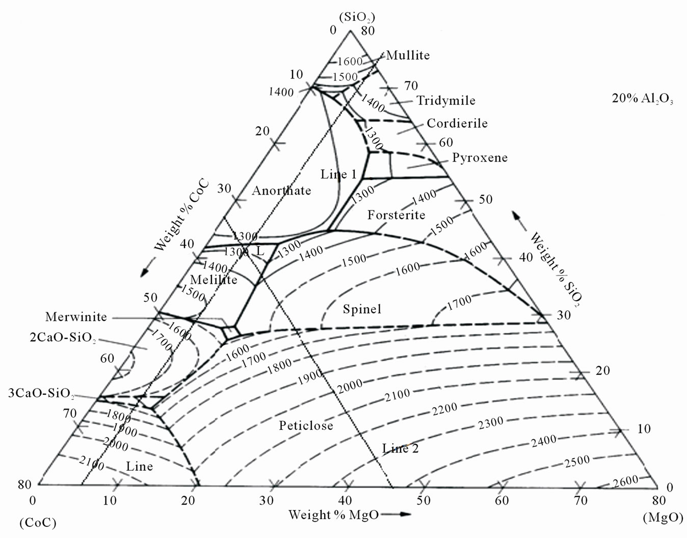
Figure 2. Slag atlas for liquidus temperature estimation for slag with 20% Al2O3.
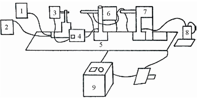
Figure 3. Line diagram of hot stage microscope. 1. Cooling water tank; 2. Cooling water recirculating tank; 3. Light source; 4. Regulating transformer for light source; 5. Optical bench; 6. High temperature electrical furnace with specimen carriage; 7. Observation and photo microscope; 8. Digital thermometer; 9. Regulating transformer for high temperature electrical furnace.
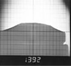
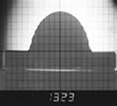

Figure 4. Different characteristic temperatures of blast furnace slag. (Sample no 12); (a) Softening Temperature; (b) Hemispherical Temperature; (c) Flow Temperature.
The liquidus temperature measured through the slag atlas method and the hot stage microscopy are compared and the error percentages are tabulated (Table 1).
3. Results and Discussions
3.1. Liquidus Temperature Measurement
The difference between liquidus temperature measured through the two methods reported above are presented in Table 1 and Figure 5.
It is clearly established that the average difference between liquidus temperatures measured by the hot stage microscopy method and that estimated using slag atlas agree closely. The difference is ±0.66% maximum, the minimum deviation being 0.22% and the maximum 1.32%.
Thus the high temperature microscopy adopted in the present work renders comparable results in relation to the age-old slag atlas method and can be considered as a novel method for estimating characteristic temperatures of the blast furnace slag.
3.2. Effect of Basicity (C/S Ratio or B2) on Characteristic Temperatures
The variation of ST, HT and FT with C/S ratio is presented in Table 2 and Figure 6. It is interesting to see
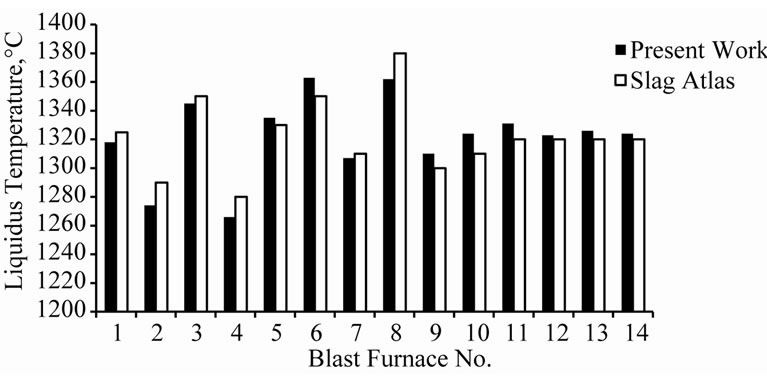
Figure 5. Comparison between liquidus temperature values obtained from present work and slag atlas.
that the flow temperature decreases with increase in the C/S ratio, the rate of decrease of the flow temperature decreasing with increase in the C/S ratio.
This is because the addition of the basic oxide CaO to the silicate network breaks down the network resulting in formation of smaller silicate groups known as anionic units or flow units [10]. The net effect is reduction of viscosity, i.e., increase in flow ability noted by the decrease in flow temperature. However, since smaller and smaller flow units require relatively higher oxygen, rendered by the addition of higher amounts of basic oxide, the progressive increase in metal oxide content is less and less effective in decreasing the flow unit size. This explains the decrease of flow temperatures at a decreas-
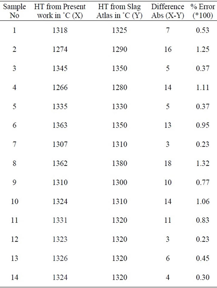
Table 1. Liquidus temperatures of slag samples as obtained from present work and slag atlas.

Table 2. Composition and flow characteristics of blast furnace slags.
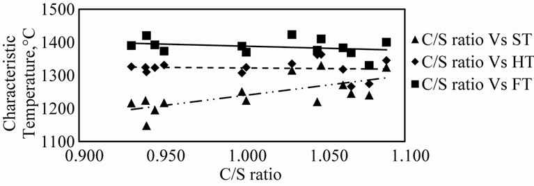
Figure 6. Variation of different characteristic temperatures with C/S ratio.
ing rate with increase of the C/S ratio [11].
It is further observed that the ST increases with the C/S ratio. The net result is that with the increase in the C/S ratio the difference between FT and ST decreases. (Figure 7). It may be appreciated that in the blast furnace it is necessary to have a narrow softening-flowing range rather than a sharp low liquidus temperature. Such a situation would generate a “Short Slag”, i.e., as soon as the slag softens, though the volume shrinks and the permeability of the bed is adversely affected, such a slag trickles down away from the site without necessarily requiring any higher availability of thermal energy. From this point of view alone it may be concluded that under the experimental conditions and within the range of compositions studied, higher values of C/S ratios are beneficial to the blast furnace process.
3.3. Effect of MgO Content on the Characteristic Temperatures
The variation of the characteristic temperatures with the MgO content is presented in Table 2 and Figure 8.
It is observed that the ST increases with increase in MgO content and though the trend is not very clear, the FT decreases with the increase in the MgO content in general. Thus, higher MgO contents within the range of compositions examined tend to generate ‘Short Slags’, decreasing the difference between the FT and ST in general.
Under the blast furnace conditions if we consider slags with softening-flowing range less than 100˚C to be short slag, it can be seen form Table 2 that slag nos. 2, 3 and 6, having a combination of high C/S ratio and high MgO content result in short slags. This is in line with the work done by V.K. Gupta et al. and R.N. Singh [12,13]. They observed that a high MgO combined with a high C/S ratio results in a short slag.
4. Conclusions
1) The high temperature microscopy is a novel method for determining the characteristic temperatures (flow characteristics) of blast furnace slag.
2) Under the range of compositions examined a high C/S ratio is beneficial for the blast furnace process as it
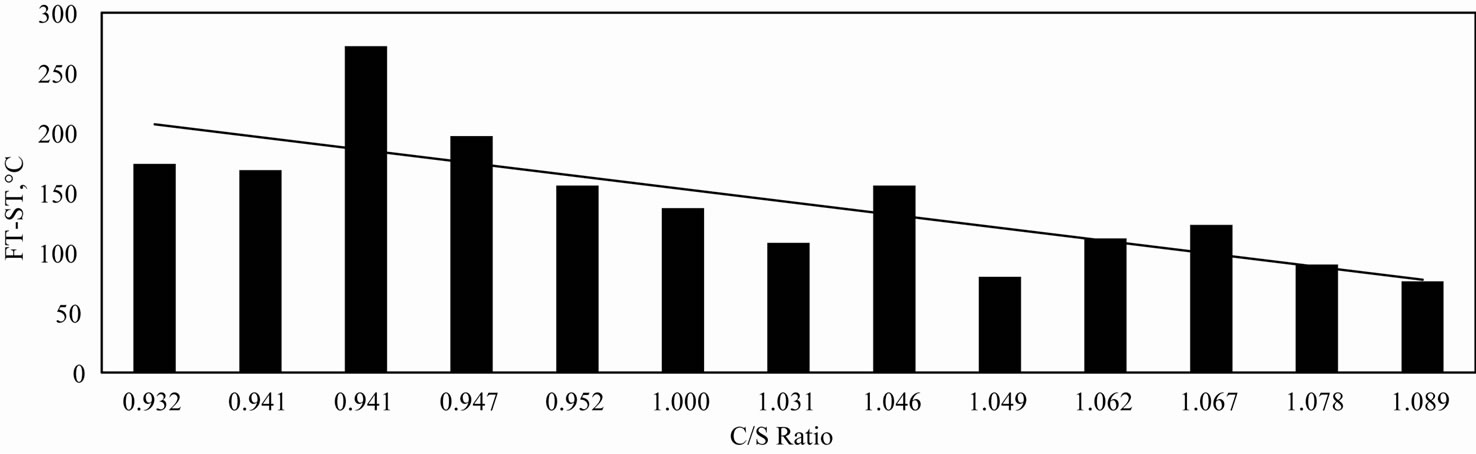
Figure 7. Variation of (FT-ST) with C/S ratio.

Figure 8. Variation of different characteristic temperatures with MgO content.
ensures the formation of a “Short Slag”.
3) Increased MgO content combined with a high C/S ratio form “Short Slags” which is advantageous to blast furnace process.
REFERENCES
- P. F. Nogueira and R. J. Fruehan, “Blast Furnace Burden Softening and Melting Phenomena: Part 1. Pellet Bulk Interaction Observation,” Metallurgical and Materials Transactions B, Vol. 35B, 2004, p. 829.
- P. Kaushik and R. J. Fruehan, “Mixed Burden Softening and Melting Phenomena in Blast Furnace Operation Part 1. X-Ray Observation of Ferrous Burden,” Ironmaking & Steelmaking, Vol. 33, No. 6, 2006, pp. 507-519. doi:10.1179/174328106X118107
- G. Clixby, “Softening & Melting of Super Fluxed Sinters and Acid Pellets,” BSC, Ironmaking Session, Tesside Laboratories, International Report, 1979.
- Yu. M. Potebnya, S. A. Gaurilko, I. A. Stroitelav, V. L. Tolstunov and L. V. Getmanova, “Influence of Phase Composition and Basicity on the Softening Temperature Range of Sinter,” Steel USSR, Vol. 3, No. 10, 1973,
- German Industrial Standard 51730.
- P. A. Taskanen, S. M. Huttunen, P. H. Mannila and J. J. Harkki, “Experimental Simulations of Primary Slag Formation in Blast Formation,” Ironmaking & Steelmaking, Vol. 29, 2002, pp. 281-286. doi:10.1179/030192302225005141
- P. K. Roy, U. N. Mishra and S. Pal, “High Temperature Properties of Iron Bearing Materials and Their Influence on Blast Furnace,” R&D Centre for Iron and Steel, SAIL, Ranchi.
- F. M. Shen, X. Jiang, G. S. Wu, G. Wei, X. G. Li and Y. S. Shen, “Proper MgO Addition in Blast Furnace Operation,” ISIJ International, Vol. 46, No. 1, 2006, pp. 65-69. doi:10.2355/isijinternational.46.65
- Slag Atlas
- U. K. Mohanty, “Thermo Physical Properties of Some Metallorthermic Slags,” Ph.D. Dissertation, R.E. College, Rourkela, 1998.
- R. C. Behera, U. K. Mohanty and A. K. Mohanty, “Viscosity and Constitution of Slags Associated with Metallothermic Extraction of Some Less Common Metals,” High Temperature Materials and Processes, Vol. 9, 1990, pp. 57-75. doi:10.1515/HTMP.1990.9.2-4.57
- V. K. Gupta and V. Sheshadri, “Studies on High Alumina Blast Furnace Slags,” Transactions of Indian Institute of Metals, Vol. 26, 1973, pp. 55-64.
- R. N. Singh, “Viscosity Measurements of High Alumina B.F. Slags,” Steel India, Vol. 7, 1984, pp. 73-83.