Journal of Power and Energy Engineering
Vol.03 No.09(2015), Article ID:59563,12 pages
10.4236/jpee.2015.39002
Comparative Assessment of Combined-Heat-and-Power Performance of Small-Scale Aero-Derivative Gas Turbine Cycles
Barinyima Nkoi, Barinaadaa Thaddeus Lebele-Alawa
Mechanical Engineering Department, Faculty of Engineering, Rivers State University of Science and Technology, Port Harcourt, Nigeria
Email: nkoi.barinyima@ust.edu.ng, lebele-alawa.thaddeus@ust.edu.ng
Copyright © 2015 by authors and Scientific Research Publishing Inc.
This work is licensed under the Creative Commons Attribution International License (CC BY).
http://creativecommons.org/licenses/by/4.0/


Received 20 July 2015; accepted 11 September 2015; published 14 September 2015
ABSTRACT
This paper considers comparative assessment of combined-heat-and-power (CHP) performance of three small-scale aero-derivative industrial gas turbine cycles in the petrochemical industry. The bulk of supposedly waste exhaust heat associated with gas turbine operation has necessitated the need for CHP application for greater fuel efficiency. This would render gas turbine cycles environ- mentally-friendly, and more economical. However, choosing a particular engine cycle option for small-scale CHP requires information about performances of CHP engine cycle options. The investigation encompasses comparative assessment of simple cycle (SC), recuperated (RC), and intercooled-recuperated (ICR) small-scale aero-derivative industrial gas turbines combined-heat-and- power (SS-ADIGT-CHP). Small-scale ADIGT engines of 1.567 MW derived from helicopter gas turbines are herein analysed in combined-heat-and-power (CHP) application. It was found that in this category of ADIGT engines, better CHP efficiency is exhibited by RC and ICR cycles than SC engine. The CHP efficiencies of RC, ICR, and SC small-scale ADIGT-CHP cycles were found to be 71%, 60%, and 56% respectively. Also, RC engine produces the highest heat recovery steam generator (HRSG) duty. The HRSG duties were found to be 3171.3 kW for RC, 2621.6 kW for ICR, and 3063.1 kW for SC. These outcomes would actually meet the objective of aiding informed preliminary choice of small-scale ADIGT engine cycle options for CHP application.
Keywords:
Aero-Derivative Gas Turbines, Combined-Heat-and-Power, Heat Recovery Steam Generator, CHP Efficiency

1. Introduction
Gas turbine is a very satisfactory means of producing mechanical power. It is designed to be highly effective in producing aligned high thrust and power [1] [2] . In contemplating environmentally-friendly gas turbine cycles in the petrochemical industry identification is made of combined-heat-and-power (CHP) as one prominent application that would make gas turbine operation very pleasant to the environment in the aspects of reducing heat energy loss to the environment, and reducing global warming. It also enhances fuel efficiency. CHP simply defined is the simultaneous generation of mechanical power and heat energy in a single system from same fuel input [3] .
Some processes in the petrochemical industry occur at relatively moderate temperatures (below 600˚C), and steam is generally the source of their heat energy supply. Such processes include the likes of refining and transformation of crude oil by separation, conversion, and purification carried out in refineries [4] , and steam cracking of heavier feedstock, polymerisation, and processing of aromatics occurring in petrochemical plants [5] . Steam could be generated by conventional boilers or heat recovery steam generators in CHP application. It is worth stating that combined-heat-and-power (CHP) generation of steam and power is presently a key energy saving, as well as environmentally-friendly technology in the petrochemical industry [5] .
The benefit of CHP is illustrated in Figure 1 where a CHP plant with a single 100 units fuel source yields about 75% overall cycle efficiency as against separate power plant and boiler source of an aggregate of 147 units of fuel yielding about 51% overall cycle efficiency [6] . In light of this, the performance of small-scale aero-derivative industrial gas turbines (SS-ADIGT) derived from helicopter gas turbines discussed by the author in ref [7] is herein analysed in CHP application.
The decision to use aero-derivative gas turbines is mainly based on economical and operational advantages. Gas turbine manufacturers have found that to reduce cost of designing and developing new gas turbines, a more effective approach is to develop high performance industrial gas turbines by modifying aircraft gas turbine engines [8] . Also, by introducing aero-derivative’s removable gas generator, better flexibility is provided which in
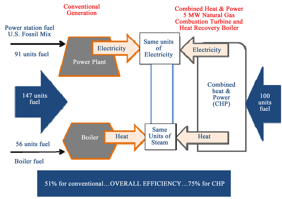
Figure 1. Energy saving benefit of CHP over traditional system [6] .
turn lead to reducing maintenance operation and enhancing gas turbine availability in industrial applications [9] . More so, implementing aero-derivative technology for industrial gas turbine has resulted in low maintenance downtime, good part-load efficiencies, and higher rate of return [10] . Besides, aero-derivative gas turbines can meet stringent NOx control requirements because they are suitable for power augmentation by steam injection. For instance, the GE LM series industrial aero-derivative gas turbines are meeting NOx requirements as low as 25 parts per million (ppm) using steam injection. Other merits of aero-derivative gas turbines include low weight-to-power ratio, compactness, and hence, lesser erection and startup time [11] [12] . Moreover, aero-de- rivative gas turbines are most suitable for highly efficient cogeneration plants, more flexible combined-cycle plants, and in mechanical drive applications for production and distribution of oil and gas [13] .
However, deciding on choice of small-scale ADIGT cycle option for CHP application poses some difficulty for engineers and decision-makers. Hence, the objective of this paper is to carry out performance comparison of simple cycle (SC), recuperated (RC), and intercooled-recuperated (ICR) small-scale ADIGT cycles in CHP, that would aid good and informed choice of turbine cycle option for the purpose of use in small-scale CHP application. The novelty of this research work is in the area of comparing the performances of SC, RC, and ICR aero- derivative gas turbine cycles in small-scale CHP. Previous works only considered CHP analysis of the simple engine cycle, and as such, considering CHP performance of advanced cycles (RC and ICR) actually presents a wider range of options for small-scale CHP engine cycle choices.
2. Materials and Methods
2.1. CHP Modelling
CHP systems are either developed as “topping cycles” or “bottoming cycles” as illustrated in Figure 2 and Figure 3 respectively [14] . Topping cycles describe systems where there occur primary power generation and subsequent heat utilization, whereas bottoming cycles pertain to systems where heat is primarily generated in a
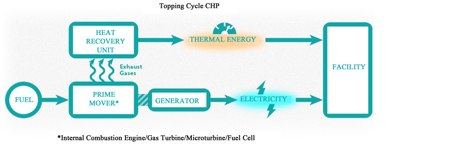
Figure 2. Topping cycle CHP (Source: [14] ).
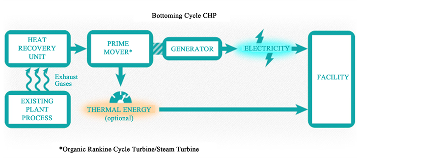
Figure 3. Bottoming cycle CHP (Source: [14] ).
process with subsequent utilisation for power generation [15] . In this work, topping cycle arrangement is adopted where power is primarily generated from gas turbine and heat recovery steam generator (HRSG) is designed to match for the purpose of process steam production. Performance parameters of the aero-derivative gas turbines discussed by the author in ref [7] are employed to determine the parameters of the HRSG.
2.1.1. HRSG Performance
A set of heat exchangers that utilises the exhaust heat of a gas turbine to produce steam is referred to as heat recovery steam generator (HRSG). Three types of HRSG are identified, namely, unfired, supplementary fired, and exhaust fired. The most common and widely used HRSG is the unfired type because it is simple in design and cheap [16] . HRSG of the unfired type is considered in this research without considering the material dimension of the heat exchangers. It is pertinent to declare that only the thermodynamic performance in terms of temperature profile of exhaust gas, steam temperature and flow, and heat capacity, of the HRSG are being modelled in this research. Pinch and approach point technology is applied in modelling the HRSG performance, and with a single steam pressure mode of operation.
2.1.2. Pinch and Approach Points Technology
Approach point is the difference between the temperature of saturated steam and the temperature of water entering the evaporator, whereas pinch point is the difference between the gas temperature leaving the evaporator and the temperature of saturated steam [16] . Steam generation is directly affected by the pinch and approach points. Also affected is the exhaust gas and steam temperature profile. For the design case of an unfired HRSG, selection is usually made of the values of pinch and approach points; pinch point ranges from 10˚C to 30˚C whereas approach point ranges from 5˚C to 15˚C based on the sizes of evaporators that can be built and shipped economically, and to maximise heat transfer rate between exhaust gas and steam streams. Figure 4 illustrates pinch point, approach point, exhaust gas and steam temperature profiles of HRSG.
Using the notations in Figure 4 above the path 4-y-x-1 indicates gas turbine exhaust gas temperature profile whereas the path a-b-c-d-e indicates steam temperature profile. ;
; ; process a-b occurs in the economiser; c-d in the evaporator; and d-e in the super-heater.
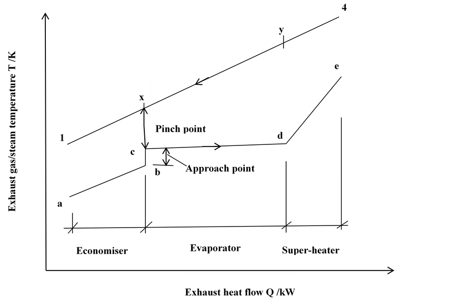
Figure 4. Single steam pressure HRSG exhaust gas/steam temperature profiles.
2.2. ADIGT-CHP Design Point Performance
To model the design point performance of a CHP plant is to match the parameters of HRSG with the design point of the gas turbine given particular consideration to desired steam flow or temperature and saturation pressure. In doing so, pinch and approach points are selected by the engineering judgement; and from gas turbine exhaust gas flow, the HRSG temperature profile, duty, and steam flow are established. Using pinch technology and thermodynamic properties of steam, the computation of CHP HRSG gas/steam temperature profile and steam flow is done as follows: Gas turbine exhaust gas temperature and mass flow are imported from gas turbine performance simulation while the HRSG pinch and steam saturation pressure (which fixes the steam saturation temperature―Tc) are selected by the engineering judgement. In this design the steam saturation pressure is 10bar. With the notations of Figure 4 the temperature of exhaust gas at pinch point (Tx) is given by Equation (1)
 (1)
(1)
where .
.
The superheated steam temperature (Te) is chosen as required by the industrial process heat demand. The steam flow (ws) is computed from total heat transfer in super-heater and evaporator using heat balance above pinch as defined by Equation (2)

 (2)
(2)
where 0.99 = heat loss factor,
0.02 = blow down factor,
 = exhaust gas flow,
 = specific heat at constant pressure of air,
 = specific enthalpy of super-heated steam,
 = specific enthalpy of saturated water,
 = specific enthalpy of saturated steam,
 = gas turbine exhaust temperature,
 = evaporator duty,
 = super-heater duty.
Equation (3) defines the super-heater duty (Qsuper)
 (3)
(3)
Gas temperature drop in the super-heater (ΔT4y) is given by Equation (4)
 (4)
(4)
This implies that exhaust gas temperature to evaporator (Ty) is calculated using Equation (5)
 (5)
(5)
Evaporator duty (Qevap) is determined with the aid of Equation (6)
 (6)
(6)
Similarly Equation (7) defines Economiser duty (Qecon)
 (7)
(7)
Gas temperature drop in the economiser (ΔTx1) is given by Equation (8)
 (8)
(8)
This implies that exhaust gas exit temperature from the economiser (T1) is calculated using Equation (9)
 (9)
(9)
Total HRSG duty (QHRSG) is computed by Equation (10)
 (10)
(10)

The electrical efficiency could be assumed, such that

where
 = gas turbine power.
Heat to power ratio of the CHP is given by Equation (11)
 (11)
(11)
Equations (1) to (11) are referred from [17]
Equation (12) is used to compute First Law CHP efficiency (η1)
 (12)
(12)
where
 = Electrical energy rate,
 = Steam energy rate,
 = Fuel mass flow in combustor,
 = LHV = Low heating value of fuel.
Equation (13) is used to compute Second Law CHP efficiency (η2)
 (13)
(13)
The denominator of Equation (13) is the availability rate of the fuel consumed,
where
 = Entropy released by fuel combustion.
 = Temperature at exhaust. Equations (12) and (13) and referred from [18] [19] .
3. Results and Discussions
3.1. Small-Scale-ADIGT-CHP Design Point Performance Analysis
The CHP design point simulation for the SS-ADIGT was done using TURBOMATCH (a gas turbine engine performance simulation code) [7] -[22] and the HRSG gas/steam temperature profiles are shown in Figure 5 while the CHP DP performance results are indicated in Table 1.
The technical performance of the simple, recuperated, and intercooled-recuperated SS-ADIGT cycles derived from helicopter engines have been analysed by the author in [7] . The superheated steam temperature for the CHP was set within the range of steam temperatures obtainable in refinery and petrochemical plants which is about 100˚C - 500˚C.
3.2. Small-Scale ADIGT-CHP Off-Design Performance
The HRSG would normally not operate at the design point due to variations in the inlet gas conditions and steam parameters. The inlet gas conditions in turn would depend on gas turbine off-design variation in ambient conditions, firing temperature, altitude, power setting, etc. This makes the CHP plant exhibits varying outputs. The CHP off-design performance was simulated with TURBOMATCH engine off-design. The off-design performances of the SS-ADIGT-CHP with changing conditions of the engines are shown in Figures 6-10.
At design and off-design conditions the RC and ICR ADIGT engines exhibit better CHP efficiency than the

Table 1. SS-ADIGT-CHP design point performance results.
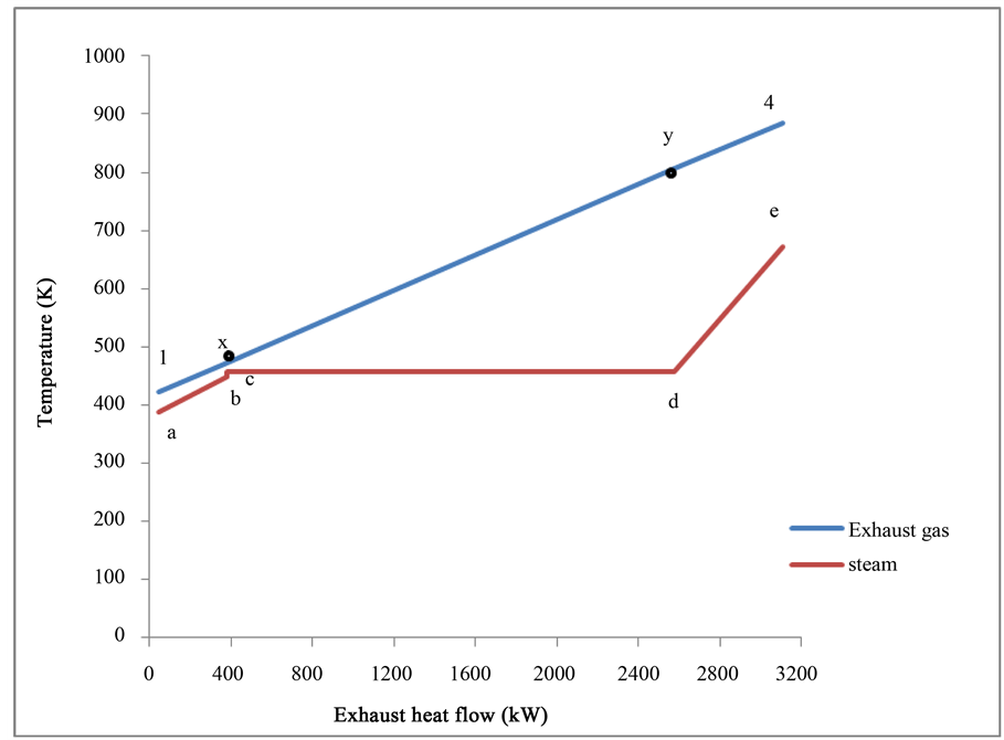
Figure 5. Single steam pressure HRSG temperature/heat profile for the SS-ADIGT-CHP.
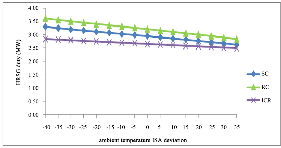
Figure 6. Effect of ambient temperature on HRSG duty.
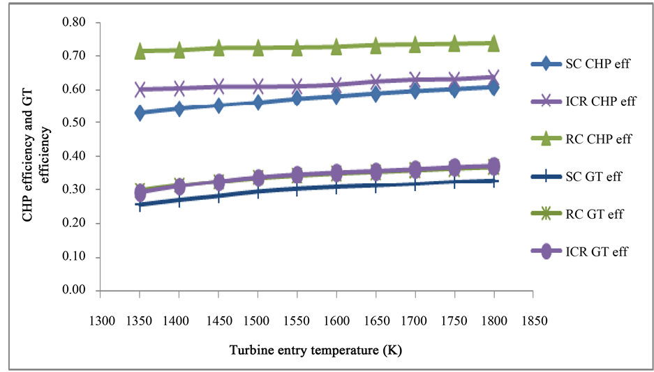
Figure 7. Variation of CHP and GT efficiencies with TET.
SC engine as shown in Figure 7, Figure 9, and Figure 10. As shown in Table 1 the CHP efficiencies of RC, ICR, and SC SS-ADIGT-CHP cycles were found to be 71%, 60%, and 56% respectively. These results compare favourably with values in the literature. For instance, a 40 kWe CHP plant located within the Queens Building at De Montfort University, was analysed to show an overall (CHP) efficiency of 77% [23] . CHP efficiency can be as high as 80% - 90%. For instance Tervola 0.5 MWe/1.13MWth CHP in Finland was found to exhibit an over- all (CHP) efficiency of 81.5% [24] . The CHP efficiencies are observed to increase with increases in turbine en- try temperature (TET), gas turbine (GT) power, ambient temperature, and HRSG duty. The percentage increases
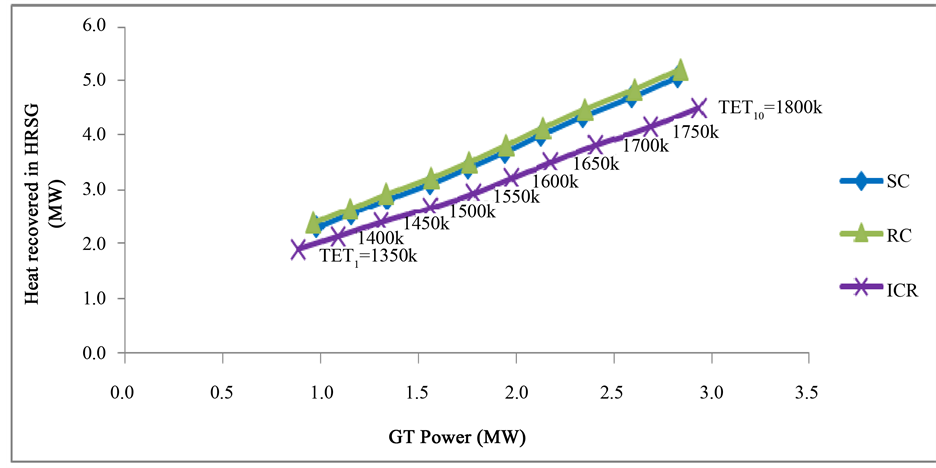
Figure 8. Variation of HRSG duty with GT power at increasing TET.
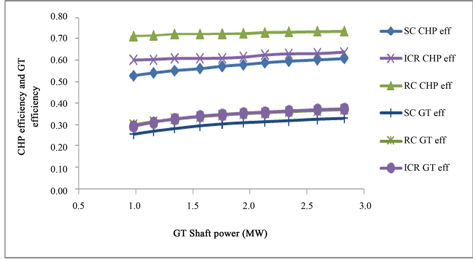
Figure 9. Variation of CHP and GT efficiencies with GT power at increasing TET.
in CHP efficiencies of RC and ICR over SC at design-point (DP) are 16.5% and 3.8% respectively. This superior performance is due to the lower heat input from burning less fuel in the advanced cycle engines. Looking at Figure 7 and Figure 9, the curve “RC GT eff” appears to coincide with that of the “ICR GT eff”, whereas actually there is some slight difference between the RC GT efficiency and ICR GT efficiency. This small difference is shown clearly at design point in Table 1 where ICR GT efficiency is slightly higher than RC GT efficiency by about 0.003.
On the other hand, the SC engine produces more HRSG duty than the ICR cycle as shown in Figure 6 and Figure 8, due to lower exhaust gas temperature and steam rate of the ICR cycle. The highest HRSG duty is produced by the RC engine because of its higher exhaust gas temperature and steam rate.
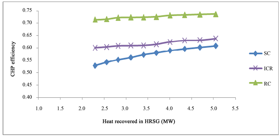
Figure 10. Variation of CHP efficiency with HRSG duty at increasing TET.
Besides, as plotted in Figure 8, the heat-to-power ratio is observed to be least in the ICR cycle than SC and RC and highest in the RC cycle at both DP and off-design (OD) conditions. In essence, this means that given a range of power output at any condition of TET and ambience, the RC cycle would generate more steam than the SC and ICR, while ICR would generate the least steam flow. This is so because GT exhaust gas temperature is highest in the RC cycle and exits the HRSG at the least temperature in the RC cycle. This creates huge drop in temperature of exhaust gas from exit of GT to exit of HRSG in the RC cycle. This exhaust gas temperature drop is smaller in SC cycle and least in ICR cycle. Hence, huge amount of heat is extracted from exhaust gas in RC cycle than SC and ICR at same conditions. At design point, the HRSG duties were found to be 3171.3 kW for RC, 2621.6 kW for ICR, and 3063.1 kW for SC as shown in Table 1.
4. Conclusion
The foregoing analysis of technical performances of small-scale aero-derivative industrial gas turbine-CHP cycles has led to the conclusions that for small-scale ADIGT-CHP, better CHP efficiency is exhibited by RC and ICR cycles than Simple engine cycle. Also, it was found that the RC engine produces the highest HRSG duty. Therefore, it could be said that performance comparison of simple, recuperated, and intercooled-recupe- rated small-scale ADIGT cycles in CHP has been achieved. This sort of analysis would actually aid concerned engineers, product developers, and other key decision-makers to logically make good and informed choice of small-scale ADIGT engine cycle option for the purpose of use in CHP application.
Acknowledgements
Very essentially, the authors would want to thank Professor Pericles Pilidis and Dr. Theoklis Nikolaidis of the Department of Power and Propulsion of Cranfield University, United Kingdom, for their invariable contributions to this research.
Cite this paper
BarinyimaNkoi,Barinaadaa ThaddeusLebele-Alawa, (2015) Comparative Assessment of Combined-Heat-and-Power Performance of Small-Scale Aero-Derivative Gas Turbine Cycles. Journal of Power and Energy Engineering,03,20-32. doi: 10.4236/jpee.2015.39002
References
- 1. Lebele-Alawa, B.T. and Jo-Appah, V. (2015) Thermodynamic Performance Analysis of a Gas Turbine in an Equatorial Rainforest Environment. Journal of Power and Energy Engineering, 3, 11-23.
http://dx.doi.org/10.4236/jpee.2015.31002. - 2. Lebele-Alawa, B.T. (2010) Axial Thrust Responses to a Gas Turbine’s Rotor-Blade Distortions. Journal of Engineering Physics and Thermophysics, 83, 991-994.
http://dx.doi.org/10.1007/s10891-010-0423-2 - 3. International Energy Agency (2007) Tracking Industrial Energy Efficiency and CO2 Emissions.
http://www.iea.org/textbase - 4. Exxonmobil (2011) Fawley Refinery and Petrochemical Plant. www.exxonmobil.co.uk/UK-English/files/Fawley_2011.pdf
- 5. Gielen, D.J., Vos, D. and Van Dril, A.W.N. (1996) The Petrochemical Industry and Its Energy Use: Prospect for the Dutch Energy Intensive Industry. Energy Research Center of the Netherland (ECN), ECN-C-96-029. April 1996, 25-45.
- 6. US EPA (2013) Combined Heat and Power Partnership: Efficiency Benefit.
http://www.epa.gov/chp/basic/efficiency.html - 7. Nkoi, B., Pilidis, P. and Nikolaidis, T. (2013) Performance of Small-Scale Aero-Derivative Industrial Gas Turbines Derived from Helicopter Engines. Journal of Propulsion and Power Research, 2, 243-253.
http://dx.doi.org/10.1016/j.jppr.2013.11.001 - 8. Bhargava, R., Blanchi, M., Peretto, A. and Spina, P. R. (2004) A Feasibility Study of Existing Gas Turbines for Recuperated, Intercooled, and Reheat Cycle. Journal of Engineering for Gas Turbines and Power, 126, 531-544.
http://dx.doi.org/10.1115/1.1707033 - 9. Najjar, Y.S.H. (2000) Gas Turbines Cogeneration Systems: A Review of Some Novel Cycles. Applied Thermal Engineering, 20, 179-197.
http://dx.doi.org/10.1016/S1359-4311(99)00019-8 - 10. Yang, W. (1997) Reduction of Specific Fuel Consumption in Gas Turbine Power Plants. Energy Conversion and Management, 38, 1219-1224.
http://dx.doi.org/10.1016/S0196-8904(96)00151-3 - 11. Keller, S.C. and Studniarz, J.J. (1987) Aero-Derivative Gas Turbines Can Meet Stringent NOx Control Requirements. Proceedings from the 9th Annual Industrial Energy Technology Conference, Houston, 16-18 September 1987, 253-260.
- 12. Roy, G.K. (2012) Selecting Heavy-Duty or Aero-Derivative Gas Turbines. Hydrocarbon Processing, 75, 57.
- 13. Doom, T.R. (2013) Aero-Derivative Gas Turbines. Case Studies on the Government’s Role in Energy Technology Innovation. American Energy Innovation Council.
http://americanenergyinnovation.org/wp-content/uploads/2013/08/Case-Gas-Turbines.pdf - 14. Center for Sustainable Energy (2014) Combined Heat and Power.
http://energycenter.org/self-generation-incentive-program/business/technologies/chp - 15. Bhatt, S.M. (2001) Mapping of General Combined-Heat-and-Power System. Energy Conversion and Management, 42, 115-124. www.elsevier.com/locate/enconman
http://dx.doi.org/10.1016/S0196-8904(00)00045-5 - 16. Ganapathy, V. (1996) Heat Recovery Steam Generator: Understanding the Basics. Chemical Engineering Process, 32-45.
- 17. Ganapathy, V. (1990) Heat Transfer—Simplify Heat Recovery Steam Generator Evaluation. Hydrocarbon Processing, March 1990, 77-82.
http://v_ganapathy.tripod.com/simphrsg.pdf - 18. Koratianitis, T. (2012) DEN107 Thermodynamics Laboratory Exercise [Course Lecture Note]. Fundamentals of General Thermodynamics. Queen Mary University of London, London.
- 19. Koratianitis, T., Grantstrom, J., Wassingbo, P. and Massardo, A.F. (2005) Parametric Performance of Combined-Co-generation Power Plant with Various Power and Efficiency Enhancements. Journal of Engineering for Gas Turbines and Power. Transactions of the ASME, 127, 65-72.
- 20. Pachidis, V.A. (2008) Gas Turbine Performance Simulation [Course Lecture Note]. Gas Turbine Simulation and Diagnostics. Cranfield University, Cranfield.
- 21. Palmer, J. (1999) The Turbomatch Scheme for Aero/Industrial Gas Turbine Engine Design Point/Off Design Performance Calculation [Course Lecture Note]. Gas Turbine Simulation and Diagnostics. Cranfield University, Cranfield.
- 22. Nkoi, B., Pilidis, P. and Nikolaidis, T. (2013) Performance Assessment of Simple and Modified Cycle Turboshaft Gas Turbines. Journal of Propulsion and Power Research, 2, 96-106.
http://dx.doi.org/10.1016/j.jppr.2013.04.009 - 23. Smith, M.A., Few, P.C. and Twidell, J.W. (1995) Technical and Operational Performance of a Small-Scale Combined-Heat-and-Power (CHP) Plant. Energy, 20, 1205-1214.
http://dx.doi.org/10.1016/0360-5442(95)00073-P - 24. Kirjavainen, M., Sipila, K., Alakangas, E., Savola, T. and Salomon, M. (2004) Small-Scale Biomass CHP Technologies Situation in Finland, Denmark and Sweden. OPET Report 12, European Commission Directorate-General for Energy and Transport. OPET CHP/DHC Cluster. Espoo, April 2004, 27.
Nomenclature