Journal of Materials Science and Chemical Engineering
Vol.2 No.4(2014), Article ID:45207,7 pages DOI:10.4236/msce.2014.24002
Electrode Property of Sintered Ceramic Based on CaMnO3 in LiOH Aqueous Solution
Takao Esaka*, Yuhta Adachi
Graduate School of Engineering, Tottori University, Tottori 680-8552, Japan
Email: *tko_esaka@chem.tottori-u.ac.jp
Copyright © 2014 by authors and Scientific Research Publishing Inc.
This work is licensed under the Creative Commons Attribution International License (CC BY).
http://creativecommons.org/licenses/by/4.0/


Received 28 February 2014; revised 27 March 2014; accepted 15 April 2014
ABSTRACT
Sintered ceramics of Ca0.9A0.1MnO3−δ (A = La, Nd, Sm, Gd and Y) were studied on their cathode properties in LiOHaq. solution. After firing, the samples were obtained as high conductivity sintered (porous) materials composed of an orthorhombic perovskite‑type phase. Next, charge discharge performances of the electrodes consisting of the sintered sample were investigated. The discharge capacity of Ca0.9Y0.1MnO3−δ was 185 mAh∙g−1 on the 1st cycling, and the 1st charging was possible by 130 mAh∙g−1. However, the 2nd discharge capacity remarkably decreased to lower than 50 mAh∙g−1. Considering no obvious charging property on the previous La‑substituted sample of Ca0.9La0.1MnO3−δ, it would mean that change of the substituent for CaMnO3 affects the electrochemical property. The roll of lithium ions, the effect of the cut‑off potential range on the cycle performance would be discussed leading to the charge/discharge results of the cell (−)Zn/LiOHaq./Ca0.9Y0.1MnO3−δ(+).
Keywords:Calcium Manganese Oxide, Lithium Hydroxide, Battery, Cathode Material

1. Introduction
When lanthanum is partially substituted for calcium sites in the perovskite‑type oxide of CaMnO3, high electronic conductivity is observed at room temperature due to the valence change of manganese and the easy change of oxygen content in the lattice [1] [2] . Therefore, this oxide is a candidate for air electrode of SOFCs [3] and/or active material in alkaline [4] -[11] and sea water batteries [12] . If this oxide was used for practical alkaline batteries, the discharge capacity density could be made larger. This is because, as the oxides show high electronic conductivity, conductive agents such as graphite are unnecessary in active materials. In practice, the sintered ceramic, which did not contain any conductive material, could be discharged; 1 g sintered ceramic of Ca0.9La0.1MnO3−δ indicated a potential plateau region at −380 mV against Hg/HgO electrode for 17 h on 10 mA cathodicdischarge in KOH solution [7] . Although the ceramic did not work as a cathode material of rechargeable battery, the discharge capacity seemed to be dependent on the electrolyte solution. Considering an incombustible aqueous lithium battery, this phenomenon is very interesting to us.
M. Manickam et al. have already carried out the investigation of batteries using LiOHaq. and MnO2 [13] - [15] . They used a few kinds of MnO2 called chemical manganese dioxide (CMD) including chemically prepared battery grade manganese (BGM) and/or electrolytic manganese dioxide (EMD) such as γ-MnO2. Especially, they reported a phenomenon not observed in KOH aq. solution, a reversible lithium insertion/desertion for γ-MnO2 to form LixMnO2. MnO2s including γ-MnO2 are all structured by linked octahedron, which are completely different from the perovskite-type one, and furthermore, not a good electronic conductor. Here, we synthesized high conductivity perovskite-type Ca0.9A0.1MnO3−δ (A = Y, Sm, Gd and so on) in porous state by a sintering method, and investigated the electrochemical properties, especially the rechargeability of the porous ceramic sample as a cathode material in LiOHaq. solution.
2. Experimental
The samples were prepared from reagent grade powders of CaCO3 and Mn2O3 and some rare earth oxides A2O3 (A = La, Nd, Sm, Gd and Y) with 99.9% purity. These materials were weighed in the defined molar ratios, mixed, temporarily pressed into pellets, and pre-fired in an alumina boat at 1200˚C in air for 10 h. To obtain porous samples for electrochemical measurements, the pre-fired samples were crushed, mixed with NH4HCO3, pressed (600 kg∙cm−3) into disks (ca. 12 mm diameter by 1 mm thickness) and sintered again at 1300˚C in air for 10 h. The crystal structure of the samples was checked by X-ray diffraction (XRD) and the sample morphology by scanning electron microscopy (SEM).Electrical conductivity of the sintered porous samples was measured by the 2-terminal ac method with 10 kHz signal in the temperature range from room temperature to 1000˚C in air. The oxygen content, i.e. 3 − δ in Ca0.9A0.1MnO3−δ at room temperature was calculated from the TGA result measured between room temperature and 1000 ˚C using the starting powder mixture.
To investigate the cathodic properties of the sample in LiOHaq. solution, the sintered sample disc (ca. 0.50 g) including no graphite was fixed on a platinum plate with a Pt lead in a polyethylene cell. This was immersed in 5% LiOHaq. solution and the current of 5 mA·g−1 was passed through the test electrode (cathode material) and a counter electrode (platinum plate). In each case, the cathode potential was measured in the window range from −0.80 to +0.60 V against an Hg/HgO electrode at 30˚C. From the discharge curves, the discharge capacities of the cathode materials were calculated.
3. Results and Discussion
The oxides shown by Ca1−xAxMnO3−δ are generally known to have fairly wide solid solution ranges. In the present experiment, the sample compositions were fixed to be x = 0.10 for various A elements. As a result, sintered (porous) samples were confirmed to be composed of an orthorhombic perovskite‑type phase in all cases. Of course, the crystal lattices somewhat changed depending on the ionic radius of A element; Ca0.9Y0.1MnO3−δ showed the most packed unit lattice among them and Ca0.9La0.1MnO3−δ the most open parallel structure, which coincided with the size of substituting elements [16] . However, the valence of manganese remaining could also influence the lattice constant. In fact, although the substituent composition is the same in Ca0.9La0.1MnO3−δ and Ca0.9Y0.1MnO3−δ, the values of 3 − δ were 2.88 to 2.91 and 2.83 to 2.85, respectively, which meant that Ca0.9La0.1MnO3−δ had a little more tetravalent manganese than Ca0.9Y0.1MnO3−δ. The samples thus obtained had ca. 60% porosity and showed high electrical conductivity; for example, the electrical conductivity of the sample Ca0.9Y0.1MnO3−δ was 1.4 × 10² S∙cm−1 at room temperature in air as shown in Figure 1.
The electrodes, constructed with porous ceramic oxides, showed stable EMFs’ over 200 mV (vs. Hg/HgO) in 5% LiOH solution at 30˚C. Figure 2 represents the typical discharge curves of the ceramic cathodes Ca0.9A0.1MnO3−δ on 5 mA discharge. In these cases, after the initial sharp potential drops, the plateau regions were observed at 350 to 400 mV followed by sharp potential drops. The discharge times corresponding to the plateau regions are not so much different depending on the “A” elements employed; the discharge time for the sample of A = La is the longest and is 2 to 3 hours longer than the previous result in 15% KOH solution. Assuming the end potential of discharge as −800 mV, the specific discharge capacity was calculated to be 200 mAh∙g−1, which was the completely the same as that we previously reported in the comparative experiments
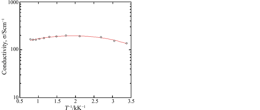
Figure 1. Electrical conductivity of the sample Ca0.9Y0.1MnO3−δ measured at room temperature in air.
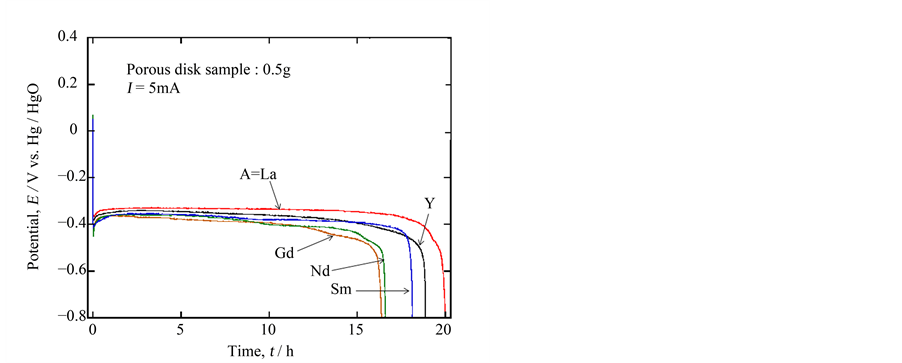
Figure 2. 5 mA discharge curves for 0.5 g porous ceramic sample of Ca0.9A0.1MnO3−δ (A= La, Y, Gd, Nd and Sm) in 5% LiOHaq. solution at 30˚C.
[7] . This meant that this type of experiment was certainly reproducible. Furthermore, the aqueous solution with lithium ion was considered to be favorable to discharge. Considering this lithium insertion, Ca0.9Y0.1MnO3−δ would be inferior to the other oxides because of the most packed structure. However, it showed good performance next to Ca0.9La0.1MnO3−δ, which may be due to the delicate structural distortion by doping of a different trivalent ion to the calcium site.
When the sample composition was represented as CaMnO3, the electrode reaction in an alkaline solution would be generally shown in the followings,
 (1)
(1)
If LiOH solution was used, the next reaction could also be expected,
 (2)
(2)
In any case, the discharge capacity due to the change of Mn4+ to Mn3+ should be 187.5 mAh·g−1 at maximum. If some manganese were substituted by a rare earth element, tri-valent manganese could be formed to reduce the content of tetra-valent manganese, which would cut down the total discharge capacity. As we observed the actual discharge capacity of 200 mAh·g−1 exceeding the maximum, we thought that the prolonged discharge time was principally due to the change of Mn4+ down to Mn2+, where the lithium insertion might be favorable in addition to hydrogen insertion. Then, we tried to check the lithium insertion into the bulk sample by ICP using the fully rinsed sample after discharge. Unfortunately, we could not strictly determine whether the obtained signal of lithium was based on the sample bulk or in the LiOH adhered tightly in the sample pore (surface). From the discharge result of the sample showing the discharge capacity less than 2 mAh·g−1 done in 1 M LiClO4/PC solution by 10 mA·g−1 as an additional experiment, the effect of lithium insertion itself would be undesirable. Of course, the XRD diffraction analysis was carried out, the result of which is mentioned in the following paragraph.
Next, we compared the performances within the samples of Ca0.9La0.1MnO3−δ and Ca0.9Y0.1MnO3−δ Figure 3(a), and Figure 3(b) comparatively show the 5 mA discharge & charge curves for the sintered porous samples of Ca0.9La0.1MnO3−δ and Ca0.9Y0.1MnO3−δ with 0.5 g weight in 5% LiOH solution. The former sample showed the 1st discharge plateau with the capacity of ca. 200 mAh·g−1, but the potential easily rose to evolve oxygen gas in the charging process.In the latter case, on the contrary, a somewhat inferior discharge performance was obtained, but the 2nd charge and the subsequent discharge were possible despite the fairly low capacity. This was a new finding on the CaMnO3−δ based material in alkaline solution. In order to check the reaction, XRD was carried out for the sample of Ca0.9Y0.1MnO3−δ after discharging and charging. As shown in Figure 4, some new peaks were mixed with those of Ca0.9Y0.1MnO3−δ itself after discharge, which could be a reason of a long plateau region during discharging. After charging, such peaks disappeared to regenerate the bulk of Ca0.9Y0.1MnO3−δ. Although the XRD peak near 2θ = 32˚ could be assigned to that of LixMnO2, the exact conclusion could not be done because of its weakness.
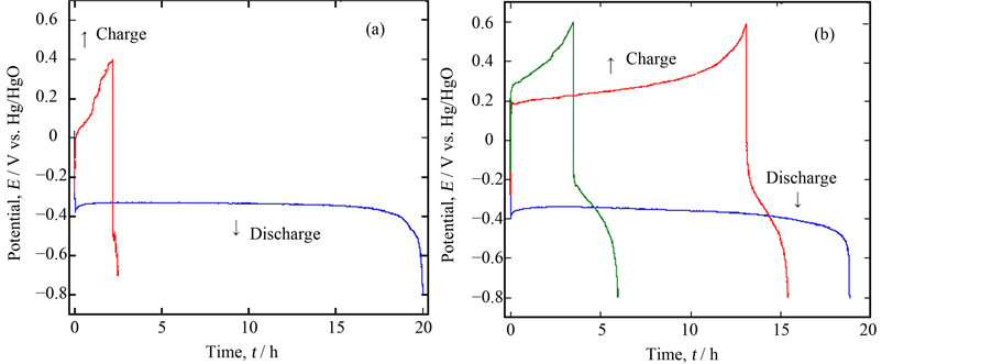
Figure 3. Comparison of the discharge/charge performance between two samples, (a) Ca0.9La0.1MnO3−δ and (b) Ca0.9Y0.1MnO3−δ.

Figure 4. XRD patterns of the sample Ca0.9Y0.1MnO3−δ; as prepared, and after discharge and charge.
Furthermore, these phenomena were recognized by SEM pictures; the sample situation was fairly different before and after discharging as seen in Figure 5, but it seemed to recover to the original situation after charging. As mentioned above, the XRD signals of the newly appeared peaks were so weak that we could not detect the exact phase of them. However, if a new phase with lower conductivity might inhibit continuous charge/discharge cycling, it might be improved by changing cutoff potentials. Figure 6 shows the experimental results done in a shallow cutoff potential range to compare with the previous one; the 1st discharge performance completely the same as before, but the potential for the quasi-plateau region considerably decreased during charging and the corresponding discharge time somewhat increased. As a result, the 3rd discharge was possible, although the total discharge capacity was extremely low. This phenomenon meant that, as expected, the main problem for charging was the property of the compound formed at the lower potential on discharge, probably the electrical conductivity.
In order to check whether the ceramic oxide Ca0.9Y0.1MnO3−δ could be employed as an actual battery material or not, a cell was set up using this oxide as a cathode material, a zinc metal as an anode material and 5% LiOHaq. solution as an electrolyte solution. Figure 7 shows a 5 mA discharge curve at 30 C. The open circuit voltage was 1.45 V. At the beginning of the discharge, the voltage sharply decreased, but a fairly good plateau region was observed at about 1.0 V; assuming the end potential of discharge 0.8 V, the discharge capacity was calculated to be 167 mAh∙g−1. In this case, on the other hand, the charge process did not carry out well, although the end potential was carefully chosen as 0.8 V which was only 0.20 V lower than that of the plateau region considering the result of Figure 6. In any case, the present result denoted that the oxide may be applicable to a kind of a primary battery system.
4. Conclusion
The sintered ceramic Ca0.9A0.1MnO3−δ (A = La, Nd, Sm, Gd and Y) showed properties as a cathode material with no conductive powder such as graphite in 5% LiOHaq. solution. The discharge capacity changed depending on
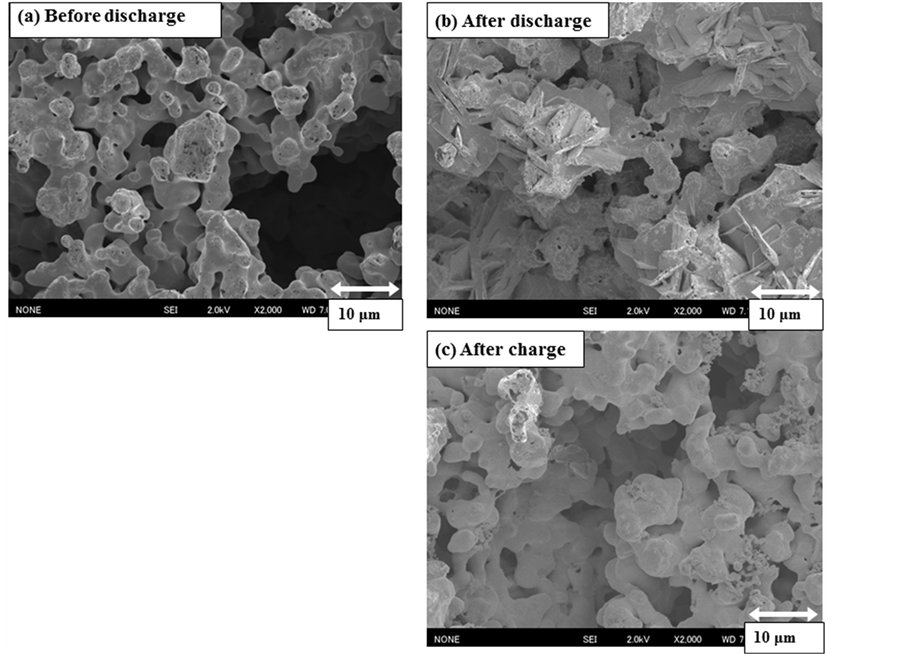
Figure 5. SEM images of the sample Ca0.9Y0.1MnO3−δ before and after discharge, and after charge.
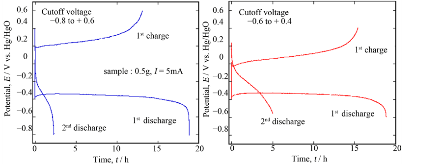
Figure 6. Comparison of the discharge/charge performance of Ca0.9Y0.1MnO3−δ depending on the cutoff voltage.
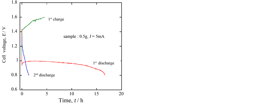
Figure 7. 5 mA discharge/charge curves for the following cell at 30˚C, (−)Zn/5% LiOHaq./Ca0.9Y0.1MnO3−δ(+).
the A elements and that Ca0.9Y0.1MnO3−δ was 190 mAh∙g−1, which was greater than 165 mAh∙g−1 of Ca0.9La0.1MnO3−δ in the previous experiment using 15% KOH aq. solution. This result shows the effect of lithium ions to promote the discharge reaction. On the other hand, the discharge capacity indicated that manganese was reduced partly from Mn4+ to Mn2+ in the oxide. By changing the cutoff potential shallow to depress formation of the compound including Mn2+, the 2nd or more discharge/charge was found to be available. Finally the cell of using zinc like (−)Zn/LiOHaq./Ca0.9Y0.1MnO3−δ(+) was found to work as a primary battery with ca. 1.0 V plateau voltage.
References
- Taguchi, H. and Shimada, M. (1986) Metal‑Insulator Transition in the System (Ca1−xLax)MnO2.97 (0.05 ≤ x ≤ 0.4). Journal of the Solid State Chemistry, 63, 290-294. http://dx.doi.org/10.1016/0022-4596(86)90180-5
- Taguchi, H. and Nagao, M. (1993) The Role of Trivalent Ion in the Metal‑Insulator Transition in (Nd0.1Ca0.9)(Mn1−xAlx)O3 and (Nd0.1‑yCa0.9+y)MnO3. Journal of the Solid State Chemistry, 105, 392-398. http://dx.doi.org/10.1006/jssc.1993.1230
- Iwahara, H., Esaka, T. and Hamajima, H. (1989) Ca1‑xCexMnO3±δ as a New Air Electrode Material for SOFC. Denki Kagaku (Presently Electrochemistry), 57, 591-594.
- Esaka, T., Morimoto, H. and Iwahara, H. (1992) Nonstoichiometry in Perovskite‑Type Oxide Ca1xCexMnO3−δ and Its Properties in Alkaline Solution. Journal of Applied Electrochemistry, 22, 821‑824. http://dx.doi.org/10.1007/BF01023724
- Esaka, T. and Morimoto, H. (1993) The Use of Oxide Ceramic Cathode in Alkaline Primary Battery. Progress in Batteries & Solar Cells, 12, 1‑4.
- Esaka, T., Morimoto, H. and Kamata, M. (1993) The Cathodic Properties of Sintered Porous Oxide Ca0.9La0.1MnO3−δ in Alkaline Solution. Denki Kagaku (Presently Electrochemistry), 61, 1028‑1029.
- Morimoto, H., Kamata, M. and Esaka, T. (1996) Nonstoichiometry of Sintered Oxide Ca0.9La0.1MnO3−δ and Its Cathodic Properties in Alkaline Solutions. Journal of the Electrochemical Society, 143, 567-570. http://dx.doi.org/10.1149/1.1836481
- Esaka, T., Kamata, M. and Ohnishi, M. (1996) Control of Oxygen Deficiency in Ca1-xLaxMnO3‑δ and Its Cathodic Properties in Alkaline Solution. Journal of Applied Electrochemistry, 26, 439-442. http://dx.doi.org/10.1007/BF00251330
- Morimoto, H., Esaka, T. and Kamata, M. (1996) Preparation of the Perovskite-Type Oxide Ca0.9Nd0.1yMnO3−δ and Its Cathodic Property in Alkaline Solution. Denki Kagaku (Presently Electrochemistry), 64, 1084-1089.
- Morimoto, H., Esaka, T. and Takai, S. (1997) Properties of the Perovskite-Type Oxide Ceramic Ca1xLa2x/3MnO3−δ as the Cathode Active Materials in Alkaline Batteries. Materials Research Bulletin, 32, 1359-1366. http://dx.doi.org/10.1016/S0025-5408(97)00113-X
- Esaka, T., Morimoto, H. and Takai, S. (1999) Application of the CaMnO3-Based High Electronic Conductivity Ceramic to Cathode Active Material in Alkaline Battery. Advance in Science and Technology, 24, 157-164.
- Morimoto, H. and Esaka, T. (2001) Cathodic Property of High Conductivity Ceramic Ca0.9La0.1MnO3−δ in Saline Solutions. Electrochemistry, 69, 612-614.
- Manickam, M., Singh, P., Issa, T.B., Thurgate, S. and Marco, R. (2004) Lithium Insertion into Manganese Dioxide Electrode in MnO2/Zn Aqueous Battery: Part I. A Preliminary Study. Journal of Power Sources, 130, 254-259. http://dx.doi.org/10.1016/j.jpowsour.2003.12.018
- Manickam, M., Singh, P., Issa, T.B., Thurgate, S. and Marco, R. (2004) Lithium Insertion into Manganese Dioxide Electrode in MnO2/Zn Aqueous Battery: Part II. Comparison of the Behavior of EMD and Battery Grade MnO2 in Zn/MnO2/Aqueous LiOH Electrolyte. Journal of Power Sources, 138, 319-322.
- Manickam, M., Singh, P., Issa, T.B., Thurgate, S. and Marco, R. (2006) Lithium Insertion into Manganese Dioxide Electrode in MnO2/Zn Aqueous Battery: Part III. Electrochemical Behavior of γ-MnO2 in Aqueous Lithium Hydroxide Electrolyte. Journal of Power Sources, 153, 165-169. http://dx.doi.org/10.1016/j.jpowsour.2005.03.184
- Shannon, R.D. (1976) Revised Effective Ionic Radii and Systematic Studies of Interatomic Distances in Halides and Chalcogenides. Acta Crystallographica Section A, 32, 751-767.
NOTES

*Corresponding author.