Journal of Materials Science and Chemical Engineering
Vol.2 No.2(2014), Article ID:42179,5 pages DOI:10.4236/msce.2014.22002
Bio-Oil Production from Biomass by Flash Pyrolysis in a Three-Stage Fluidized Bed Reactors System
1Department of Metallurgical Engineering, University of Concepcion, Casilla 53-C, Concepción, Chile
2Fundación Chile, Avenida Parque Antonio Rabat Sur 6165, Vitacura, Santiago, Chile
3Centre for Technological Development-UDT, Parque Industrial Coronel, Concepción, Chile
Email: iwilkomi@udec.cl, emiliomorenoh@gmail.com, a.berg@udt.cl
Copyright © 2014 I. Wilkomirsk et al. This is an open access article distributed under the Creative Commons Attribution License, which permits unrestricted use, distribution, and reproduction in any medium, provided the original work is properly cited. In accordance of the Creative Commons Attribution License all Copyrights © 2014 are reserved for SCIRP and the owner of the intellectual property I. Wilkomirsk et al. All Copyright © 2014 are guarded by law and by SCIRP as a guardian.
Received December 7, 2013; revised January 7, 2014; accepted January 14, 2014
KEYWORDS
Fast Pyrolysis; Fluidized Bed Reactors; Bio-Oil from Saw Dust
ABSTRACT
A novel system of fast pyrolysis and vapour quenching was developed at pilot scale to obtain bio-oil from biomass. The system uses three-stage of interconnected fluidized bed reactors that continuously circulate silica sand from an internal pyrolysis reactor to a second external annular reactor for char burning, which generates most of the heat required by the pyrolysis reactor, and a third sand-preheating reactor that burns non-condensable pyrolysis gas. The hot vapours, after high temperature cleaning, are quenched in a flash cooling system. The process generates up to 62% of bio-oil, 25% of char and 13% of non-condensable gas. The heat requirements for the total system are provided by burning part of the char and non-condensable gases generated in the pyrolysis step and by preheating the fluidizing gas for the pyrolysis reactor.
1. Introduction
Fast or flash pyrolysis is a high temperature process to convert biomass into liquid, gaseous and solid products in absence of oxygen. The main characteristics of this process are:
Ÿ high heating rate of the biomass to reach the pyrolysis temperature of the solids in a very short period of time.
Ÿ Close control of the temperature and reaction time of the solids and vapours in the pyrolysis reactor.
Ÿ Fast quenching of the vapours generated by pyrolysis.
Depending upon the kind of biomass used, pyrolysis time and temperature and cooling rate of the vapours, from 50% up to 75% of the biomass can be converted to bio-oil, with the remainder distributed as non-condensable gases and charcoal. The complex compounds formed according the origin of the biomass and the pyrolysis conditions can generate either allobiosan and other kind of anhydro-oligosaccharides, levoglucosan, hydroxyacetaldehyde, levoglucosenone or synthesis gas.
Due to the potential that this process has, flash pyrolysis of biomass could be alternative to conventional fossil fuels, with zero carbon footprint and high yield of lignocellulose material to bio-oil.
1.1. Flash Pyrolysis Systems for Biomass
Several systems are used or have been proposed to comply with the fast pyrolysis requirements in terms of reaction time, heat input, cleaning of gases and fast quenching of the organic vapours generated.
Most of the systems use fluidized beds and silica sand as the main heat transfer media, although a rather large variety of other reactors and devices have been used, such as screw reactors, ablative plates and cones and pneumatic transport reactors. This is well documented elsewhere [1,2].
1.2. Heat Transfer and Reaction Time Requirements
In order to have a successful flash pyrolysis system, a large amount of heat must be fast and continuously transfered to the biomass material to sustain the pyrolysis reactions, which requires an average of 230 J/g [3]. For fluidized beds systems, this imposes a serious constrain for the materials generally used for heat transfer like silica or alumina sand, since they have a rather low heat capacities (0.6 - 0.7 J/g), which represents a requirement of about 5 gram of silica sand at 580˚C per g of sawdust for a pyrolysis reaction at 500˚C. Other options, such as pre-heating the fluidizing gas for the pyrolysis reactor, can’t provide all of the heat requirements due to the low heat capacity of the gases.
To maximize the amount of heat transferred into a fast pyrolysis reactor, a combined system was designed [4] that comprised heat transfer through the reactors wall, preheating the fluidizing gas and preheating silica sand. The system employs three separate but interconnected fluidized bed reactors:
Ÿ a flash pyrolysis reactor sited inside of a char burning reactor;
Ÿ an external annular char burning reactor;
Ÿ a silica sand preheating reactor.
This configuration permits a flexible operation in terms of heat requirements and also allows us to maintain the vapours cleaning train above 400˚C, up to the vapoursquenching stage.
2. Three-Stage Fluidized Bed Fast Pyrolysis System
2.1. Fast Pyrolysis System Developed
To develop the concept, a three years program was undertaken, which includes the design and construction of a pilot plant. The process diagram of the 25 k/h nominal capacity of dry sawdust pilot plant is shown in Figure 1. In Figures 2-4 is shown the plant installed at UDT, (University of Concepción, Chile).
The main technical characteristics of the reactors used in this system are as follows:
2.1.1. Flash Pyrolysis Reactor
The Flash Pyrolysis Reactor is 15 cm diameter by 162 cm total height, with a shallow fluidized bed of 55 cm depth of silica sand −35/+150 mesh. The operating superficial gas velocity at 480˚C - 520˚C is 50 - 55 cm/s. The −3 mm dry saw dust is fed pneumatically using noncondensable pyrolysis gas (PG) as the transport gas by means of a 18 mm diameter SS lance inmersed in the fluidized bed. The gas velocity in the lance is 14 - 15 m/s which permits a rapid dispersion of the feed inside the
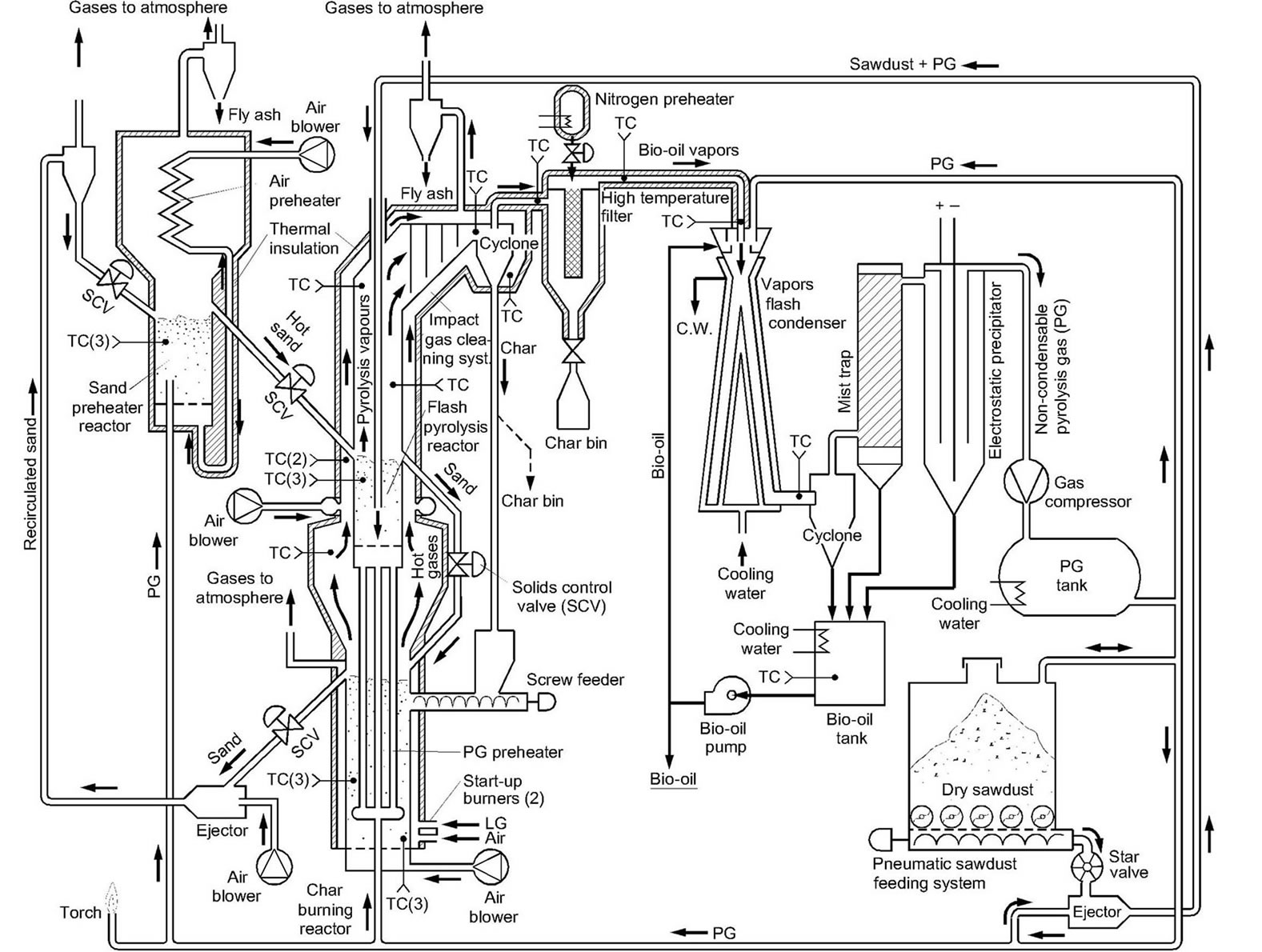
Figure 1. Process flowdiagram of the fast-pyrolysis pilot plant.
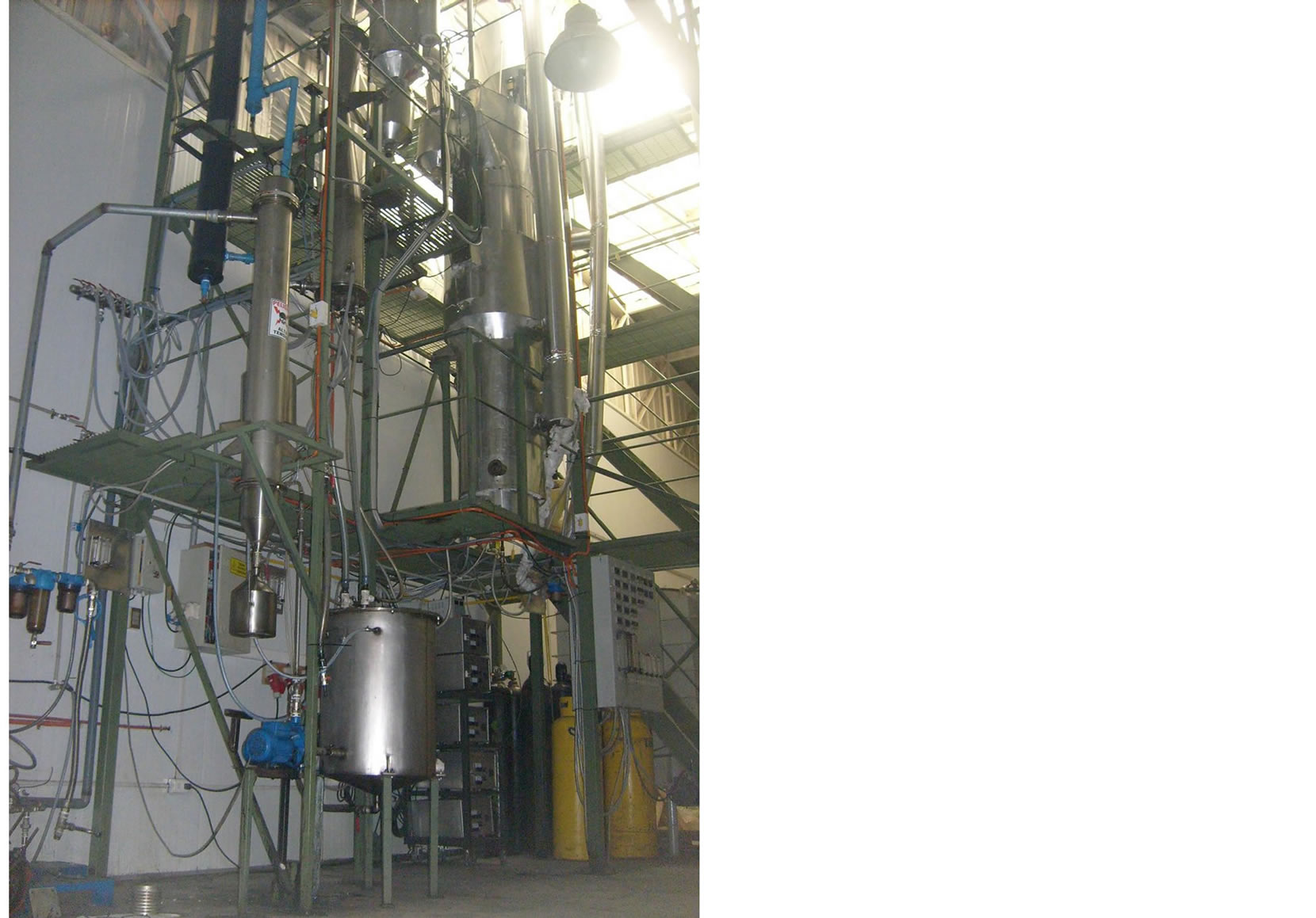
Figure 2. General view of the flash-pyrolysis pilot plant.

Figure 3. Pneumatic sawdust feeding.

Figure 4. Fast pyrolysis pilot-plant Reactor.
fluidized bed of silica sand and char. Reaction (pyrolysis) time is estimated at 2 sec., while the mean residence time of the silica sand inside the bed is 16 - 18 min for 25 kg/h sawdust feed rate, assuming a backmixed condition of the solids in the bed.
The char generated in the pyrolysis reactor, mixed with silica sand, continuously overflow into the outer annular Char Burning Reactor through a solenoid-operated Solids Control Valve (SCV) connected to a variable timer.
The dry sawdust is contained a pressurized 2 cu.m. bin with a live botton of five variable speed screw feeders that discharge into a single high–speed screw which discharge into a rotary star valve and this into a PG-operated ejector which send the gas–solid stream to the feeding lance.
2.1.2. Char Burning Reactor
The char mixed with silica sand discharging from the Flash Pyrolysis Reactor is burn with air in a 30 cm diameter by 185 cm height outer annular Char Burning Reactor which operates at 750˚C - 800˚C with a spatial gas velocity of 65 - 70 cm/s. Additional char or sawdust can be fed into the reactor by means of a variable speed screw feeder.
The reactor has an expanded freeboard to collect the coarser fraction of the silica sand and fly ash elutriated. In the upper section of the expansion zone, tempering air can be injected through an annular pipe ring, which by controlling the temperature of the hot gases, also can control the heat transfered to the flash pyrolysis bed through the reactor’s walls.
In its ascending flow, the hot gases also maintain the upper section of the pyrolysis reactor and vapours cleaning system above 400˚C, up to the hot filter. The off gases are finally cleaned of fly ash in a cyclone and send to the atmosphere.
2.1.3. Sand Preheating Reactor
Sand and some remnant ashes continuously overflow from the Char Burning Reactor through a SCV into an air-operated ejector that pneumatically transport the solids up to a cyclone, which discharge the solids through an other SCV into the upper Sand Preheating Reactor, where PG is burn to raise the temperature of the sand to 580/590˚C.
The reactor is 25 cm diám. and 238 cm height and its fluidized with air, which also burn the PG inside the bed. Additional heat is added to the reactor by means of external heating coils at bed level since the heat generated by the PG is not enough to balance the heat requirements for this size of reactor.
The fluidizing air for the Sand Preheating Reactor is preheated to 250˚C - 280˚C in a cross-flow heat exchanger located in the freeboard of the reactor. The bed temperature is maintained at 580˚C/590˚C and the spatial gas velocity at 52 - 55 cm/s. The hot silica sand overflowing the reactor is fed into the Flash Pyrolysis Reactor through a SCV, closing in this form the loop of continuous recirculation of silica sand between all three reactors.
Most of the char ashes are elutriated from the Char Burning Reactor, with the remaining being elutriated from the Sand Preheating Reactor. These are collected in a cyclone from the off gases.
2.2. Vapour Cleaning and Cooling System
2.2.1. Vapours Cleaning
The hot pyrolysis vapours generated in the Fast Pyrolysis Reactor are cleaned in three consecutive stages: first in an impact laberintic-system that collects virtually of the sand and some of the char elutriated, which are returned by gravity to the bed. The vapours are then cleaned in a hot cyclone which separates most of the char generated in the process and some silica sand not collected in the impact system. This material discharges into a bin, and part of this material is send to the char burning reactor, according to the heat requirements.
Finally, the hot vapours at 400˚C - 420˚C, are cleaned in a hot filter made of Nextel(R) fabric (B2O3-Al2O3-SiO2). The filter is cleaned every 10 min by a half second 350˚C high-pressure nitrogen blow-back pulse.
The Flash Pyrolysis Reactor and the Vapours Cleaning System up to the hot filter is located inside the annular Char Burning Reactor, which surround it. This permits to maintain all of this equipment well above of the condensation temperature of bio-oil or tar.
2.2.2. Vapours Quenching System
The hot clean vapours emerging from the hot filter are rapidly quenched in a water jacketed Venturi-type condenser and an internal water-cooled diverter cone (Figure 1). In the upper section of the vapours inlet, cold biooil (20˚C - 25˚C) continuously overflows along the walls forming a liquid film that avoid tar buildup along the walls. Additional heat is removed by injecting cold either PG or bio–oil through an annular ring at the vapours inlet.
The condensed bio-oil is collected in a cyclone and then in a mist collector tower. This accounts for about 95% - 98% of the total bio-oil produced. The remaining bio-oil, mainly in the form of aerosol, is collected in a wet ESP of 15,000 V. Additional disposable paper filters are used to avoid residual aerosols entering into the PG compressor. The bio-oil is stored in a 200 lt tank with a water cooling jacket.
PG is compressed to 4 bar and stored in a 2 cu.m. tank from where it is send to the Fast Pyrolysis Reactor; Sand Preheating Reactor; Pneumatic Feeding System and Vapours Quenching System. Excess PG can be burn in an external torch.
3. Results of the Pilot Plant Operation
The pilot plant was commissioned on March 2011 and it took a period of 8 months of adjustments and modifications to become fully operative, mainly due to modifications in the heating start-up systems, vapours quenching system and bio-oil and aerosol collection, which requires to add a mist trap collector and a wet ESP. Results of six month trials are given in Table 1.
The influence of the pyrolysis temperature on the bio-oil yield is shown in Figure 5. These results indicate that for this kind of sawdust and reaction time, the maximum yield of sawdust to bio-oil is about 62%. Temperature control is achieved adjusting the gases temperature injecting cool air into the upper section of the char burning reactor freeboard and by adjusting the sawdust feed rate, while the average reaction time of the feed inside the bed is given by the backmixed condition of bed fluidizing gas velocity and bed depth.
The relatively high generation of char may indicate that the pyrolysis reaction time is longer than the estimated, possibly by constrains due to the low heat conduction of the pine sawdust particles.
Limitations in the feeding system (star valve) do not permit to increase the feed rate above 10 kg/h. This was modified later to increase its capacity up to the design capacity of 25 kg/h.
The average physico-chemical properties of the bio-oil produced in the pilot plant is shown in Table 2.
The heat balance performed on the pilot unit shows that 54% of the heat required by the pyrolysis reactions comes from the heat transfered through the walls from the hot gases generated in the Char Burning Reactor and 14% from the preheated fluidizing PG, which represents a total of 68% of the heat apported by the Char Burning Reactor. The remaining 32% comes from the preheated silica sand.
The distribution of the heat requirements for the pyrolysis reactor is shown in Table 3.

Figure 5. Bio-Oil yield from pine sawdust as a function.
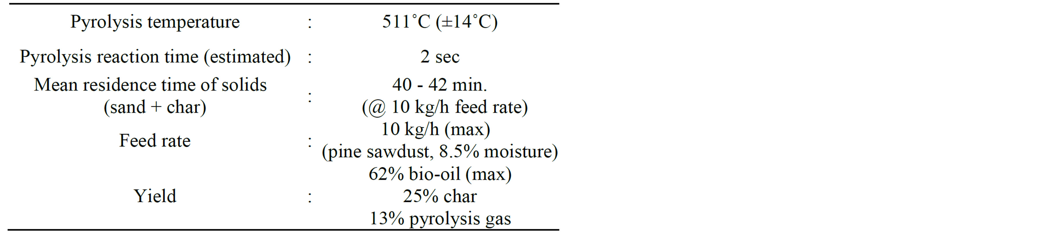
Table 1. Results of operation of the flash pyrolysis pilot plant.
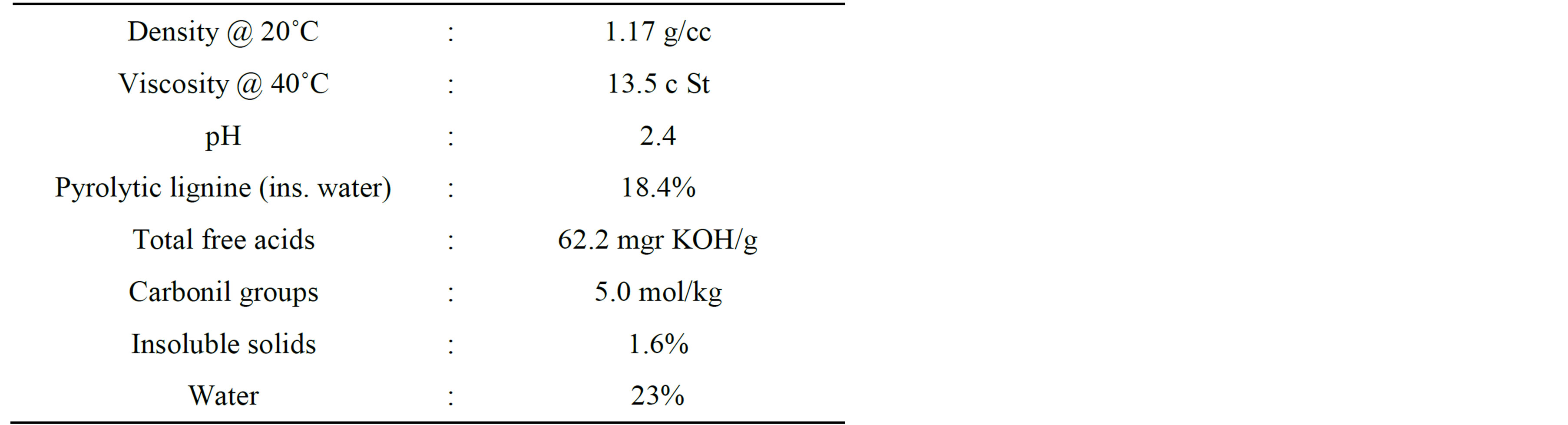
Table 2. Bio-oil physico–chemical properties (average).

Table 3. Heat contributions to the pyrolysis reactor (%).
4. Conclusions
A novel system for flash pyrolysis of biomass of three interlocked fluidized beds has been developed at pilot scale. The system permits a mass convertion of up to 62% of pine sawdust to bio-oil, with 25% to char and 13% as pyrolysis gas.
The heat transfer distribution shows that 54% of the heat requirements of the pyrolysis reactor are transferred through the reactor’s walls with 14% from the preheated fluidizing PG gas and the balance of 32% from the preheated silica sand.
Acknowledgements
This work was supported by the Chilean FONDEF Program through the Research Grant No. D07-I-1137, with additional funding from Conmetal Ltda., Rebisa S.A., EST Ltda., Biolet Ltda. and Forestal Conquistador Ltda. The participation of Mr. Cristian Muñoz and Héctor Grandón of UDT in putting together and running the pilot plant is greatly appreciated.
REFERENCES
- A. V. Bridgwater, S. Czernik and J. Piskorz, “The Status of Biomass Fast Pyrolysis,” In: A. V. Bridgwater, et al., Eds., Fast Pyrolysis of Biomass: A Handbook, Vol. 2, CL Scientific Publishing Services Ltd., Birmingham, 2002, pp. 1-22.
- J. P. Diebold and A. V. Bridgwater, “Overview of Fast Pyrolysis of Biomass for the Production of Liquid Fuels,” In: A. V. Bridgwater, et al., Eds., Fast Pyrolysis of Biomass: A Handbook, Vol. 1, CL Scientific Publishing Services Ltd., Birmingham, 1999, pp. 14-32.
- I. Wilkomirsky, “Pat. Pend. in Chile, USA, Canada, EC and Brasil, 2008-2010.”
- J. Rath, M. G. Wolfinger, G. Steiner, G. Krammer, F. Barontini and V. Cozzani, “Heat of Wood Pyrolysis,” Fuel, Vol. 82, 2003, pp. 81-91. http://dx.doi.org/10.1016/S0016-2361(02)00138-2