Open Journal of Acoustics
Vol.4 No.2(2014), Article
ID:46050,15
pages
DOI:10.4236/oja.2014.42006
A Study on the Multiple Composite Piezoelectric Motor
Jwo Ming Jou
Department of Mechanical Engineering, Cheng Shiu University, Kaohsiung City, Taiwan
Email: joujm@csu.edu.tw
Copyright © 2014 by author and Scientific Research Publishing Inc.
This work is licensed under the Creative Commons Attribution International License (CC BY).
http://creativecommons.org/licenses/by/4.0/


Received 10 March 2014; revised 10 April 2014; accepted 12 May 2014
ABSTRACT
In this study, we major discuss a multiple composite piezoelectric motor. It is made by the base, the multiple composite piezoelectric stator and the preload adjusting module. The multiple composite piezoelectric stator is composed of the base, the first actuating element, the second actuating element and stator. The first actuating element is composed of the longitudinal and the first bending vibration modules, in which the first bending vibration module includes the horizontal and vertical bending vibration modules. And the second actuating element or bending vibration modules, wherein the second actuating element also includes the horizontal and vertical bending vibration modules. In addition, the preload adjusting module includes the limiting element, spring, washer and nut. In order to obtain the best vibration modes of the multiple composite piezoelectric motor, we use the ANSYS code to simulate. And so as to get the better performance and efficiency relate to the previous similar type’s motor under the same driving conditions, we try to use different vibration modules or modes to drive the multiple composite piezoelectric motor, including the longitudinal, the first bending, the second bending and the multiple vibration modules or modes by experiments. According to the results of the simulations and experiments, we found that the multiple composite piezoelectric motor has better rotational speed, loading ability and conversion efficiency of direction relate to the previous similar type’s motor. Where the maximum rotational speed multiple composite piezoelectric motor is up to 600 rpm under conditions of 180 Vp-p driving voltage, 37.8 kHz driving frequency, 00 driving phase angle and 12.1 gw loading. And the maximum loading ability is 2500 gw under conditions of 180 Vp-p driving voltage, 37.8 kHz driving frequency, 00 driving phase angle and 6rpm rotational speed.
Keywords:Multiple Composite Piezoelectric Motor (MCPM), Longitudinal Vibration, Bending Vibration, Multiple Vibration, Conversion Efficiency of Direction

References
- Ohnishi, O., Myohga, O., Uchikawa, T., Tamegai, M., Inoue, T. and Takahashi, S. (1989) Piezoelectric Ultrasonic Motor Using Longitudinal-Torsional Composite Vibration of a Cylindrical Resonator. IEEE 1989 Ultrasonics Symposium Proceedings, 2, 739-743. http://dx.doi.org/10.1109/ULTSYM.1989.67085
- Takeoka, A., Ishikawa, A., Suzuki, M., Niki, K. and Kuwano, Y. (1989) Meissner Motor Using High-Tc Ceramic Superconductors. IEEE Transactions on Magnetics, 25, 2511-2514.
- Ohnishi, O., Myohga, O., Uchikawa, T., Tamegai, M., Inoue, T. and Takahashi, S. (1993) Piezoelectric Ultrasonic Motor Using Longitudinal-Torsional Composite Resonance Vibration. IEEE Ultrasonics, Ferroelectrics, and Frequency Control, 40, 687-693.
- Kawasaki, O., Nishikura, T., Sumihara, M., Ohtsuchi, T., Takeda, K., Nojima, T. and Imada, K. (1993) A Small Size Ultrasonic Motor. Systems, Man and Cybernetics, 1993. “Systems Engineering in the Service of Humans”, Conference Proceedings, International Conference, 1, 435-440.
- Shigeki, T., Shigeru, S., Zhang, G.Q., Yasutaro, M. and Kazuto, N. (1994) Multi Degree of Freedom Spherical Ultrasonic Motor. Industrial Electronics, Control and Instrumentation, IECON '94., 20th International Conference, 2, 900-905.
- Toyama, S., Sugitani, S., Zhang, G.Q., Miyatani, Y. and Nakamura, K. (1995) Multi Degree of Freedom Spherical Ultrasonic Motor. Robotics and Automation, 1 Proceedings, 1995 IEEE International Conference, 3, 2935-2940.
- Kurosawa, M., Takahashi, M. and Higuchi, T. (1996) Ultrasonic Linear Motor Using Surface Acoustic Waves. IEEE Ultrasonics, Ferroelectrics, and Frequency Control, 43, 901-906.
- Morita, T., Kurosawa, M. and Higuchi, T. (1997) A Cylindrical Micro Ultrasonic Motor Fabricated by Improved Hydrothermal Method. Solid State Sensors and Actuators, TRANSDUCERS '97 Chicago, International Conference, 1, 49-52.
- Wakai, T., Kurosawa, M.K. and Higuchi, T. (1998) Transducer for an Ultrasonic Linear Motor with Flexible Driving Part. Ultrasonics Symposium, Proceedings, 1998 IEEE, 1, 683-686.
- Li, C.D. and Zhao, C.S. (1998) A Large Thrust Linear Ultrasonic Motor Using Longitudinal and Flexural Modes of Rod-Shaped Transducer. Ultrasonics Symposium, 1998. Proceedings, IEEE, 1, 691-694.
- Takemura, K. and Maeno, T. (2000) Characteristics of an Ultrasonic Motor Capable of Generating a Multi-Degrees of Freedom Motion. Robotics and Automation, Proceedings, ICRA '00. IEEE International Conference, 4, 3660-3665.
- Nakamura, Y., Kurosawa, M.K., Shigematsu, T. and Asai, K. (2003) Effects of Ceramic Thin Film Coating on Friction Surfaces for Surface Acoustic Wave Linear Motor. Ultrasonics, 2003 IEEE Symposium, 2, 1766-1769. http://dx.doi.org/10.1109/ULTSYM.2003.1293254
- Guo, J.F., Gong, S.J., Guo, H.X., Liu, X. and Ji, K.H. (2004) Force Transfer Model and Characteristics of Hybrid Transducer Type Ultrasonic Motors. IEEE Ultrasonics, Ferroelectrics, and Frequency Control, 52, 387-395.
- Leinvuo, J.T., Wilson, S.A., Whatmore, R.W. and Cain, M.G. (2006) Flextensional Ultrasonic Piezoelectric Micro-Motor. IEEE Ultrasonics, Ferroelectrics, and Frequency Control, 53, 2357-2366.
- Shi, S.J., Chen, W.S. and Liu, J.K. (2006) A High Speed Ultrasonic Linear Motor Using Longitudinal and Bending Multimode Bolt-Clamped Langevin Type Transducer. Mechatronics and Automation, Proceedings of the 2006 IEEE International Conference, 612-617.
- Luo, L.H., Zhu, H., Zhao, C.S., Wang, H.X. and Luo, H.S. (2007) Cylinder-Shaped Ultrasonic Motors 4.8 mm in Diameter Using Electroactive Piezoelectric Materials. Applied Physics Letters, 90, 052904-052904-3.
- Kobayashi, A., Kanda, T. and Suzumori, K. (2007) Driving Performance of a Cylindrical Micro Ultrasonic Motor. Intelligent Robots and Systems, 2007. IROS 2007. IEEE/RSJ International Conference, 3809-3814.
- Ichihara, T., Kanda, T. and Suzumori, K. (2008) Design and Evaluation of Low-Profile Micro Ultrasonic Motors Using Sector Shaped Piezoelectric Vibrators. Intelligent Robots and Systems, IROS 2008. IEEE/RSJ International Conference, 588-593.
- Wajchman, D., Kuang-Chen Liu, Friend, J. and Yeo, L. (2008) An Ultrasonic Piezoelectric Motor Utilizing Axial-Torsional Coupling in a Pretwisted Non-Circular Cross-Sectioned Prismatic Beam. IEEE Ultrasonics, Ferroelectrics, and Frequency Control, 832-840.
- Yao, Z.Y., Yang, D., Wu, X. and Zhao, C.S. (2008) Structure Design Method of Bar-Structure Linear Ultrasonic Motors. Ultrasonics Symposium, IUS 2008. IEEE, 639-642.
- Sheng, M.W., Chen, W.S., Liu, J.K. and Shi, S.J. (2009) Study and Test of a Double-Rotor Ultrasonic Motor with Symmetrical Longitudinal-Torsional Converter. Applications of Ferroelectrics, ISAF 2009. 18th IEEE International Symposium, 1-4.
- Chu, X.-C., Chen, X.-Y. and Li, L.-T. (2009) A Miniature Disk-Pivot Piezoelectric Motor with Double Rotors. Piezoelectricity, Acoustic Waves, and Device Applications (SPAWDA) and 2009 China Symposium on Frequency Control Technology, Joint Conference of the 2009 Symposium, 107.
- Chen, P.-H., Wang, Y. and Huang, W.-Q. (2009) Design of a New Type of Piezoelectric Linear Motor Base on Non-Resonant Vibration. Piezoelectricity, Acoustic Waves, and Device Applications (SPAWDA) and 2009 China Symposium on Frequency Control Technology, Joint Conference of the 2009 Symposium, 105.
- Kondo, S., Koyama, D. and Nakamura, K. (2010) Miniaturization of the Traveling Wave Ultrasonic Linear Motor Using Bimorph Transducers. Ultrasonics Symposium (IUS), 2010 IEEE, 1482-1485.
- Wang, Y., Jin, J.M. and Huang, W.Q. (2010) A Compact Ultrasonic Motor Using Two in Plane Modes. Piezoelectricity, Acoustic Waves and Device Applications (SPAWDA), 2010 Symposium, 171-174.
- Qi, Z., Liang, P., Ting, M., Rang, K. and Hua, F. (2011) Piezoelectric Rotary Motor Based on Active Bulk Torsional Element With Grooved Helical Electrodes. Mechatronics, IEEE/ASME.
- Liu, Y., Liu, J. and Chen, W. (2011) A Cylindrical Traveling Wave Ultrasonic Motor Using a Circumferential Composite Transducer. Ultrasonics, Ferroelectrics and Frequency Control, 58, 2397-2404.
- He, S.Y., Chiarot, P.R. and Park, S. (2011) A Single Vibration Mode Tubular Piezoelectric Ultrasonic Motor. IEEE Ultrasonics, Ferroelectrics, and Frequency Control, 58, 1049-1061.
- Liu, Y.X., Chen, W.S., Liu, J.K. and Shi, S.J. (2011) A High-Power Linear Ultrasonic Motor Using Longitudinal Vibration Transducers with Single Foot. Ultrasonics, Ferroelectrics and Frequency Control, 57, 1860-1867.
- Jou, J.-M. (2011) A Study on the Multi-Block Piezoelectric Car. 2011 International Symposium on Mechatronic and Biomedical Engineering & Applications, 123-128.
- Jou, J.-M. (2013) A Study on the Rod Type Ultrasonic Motor. Advanced Materials Research, 716, 600-607.
- Jou, J.-M. (2013) A Study on the Piezoelectric Motor of High Actuating Force. Life Science Journal, 10, 242-248.
- Jou, J.-M. (2013) A Study on the Composite Type Piezoelectric Motor. Open Journal of Acoustics, 3, 88-95. http://dx.doi.org/10.4236/oja.2013.33014
2. Composition, Operation Principle and Trajectory
In this study, the multiple composite piezoelectric motor is made by the multiple composite piezoelectric stator, rotor, preload adjusting module and shaft, shown as Figures 1-3. In which the multiple composite piezoelectric stator is composed of the base, the first actuating element, the second actuating element and stator, shown as Figure 3. In addition the preload adjusting module includes the limiting element, spring, washer and nut. As for the first actuating element is composed of the longitudinal vibration module and the first bending vibration module (which the first bending vibration module includes the horizontal bending vibration module and the vertical bending vibration modules), shown as Figures 3-4. And the second actuating element or bending vibration module (which the second bending vibration module includes the horizontal bending vibration module and the vertical bending vibration modules), shown as Figure 3 and Figure 5. Finally, we can found the motion trajectory or behavior of the multiple composite piezoelectric stator or motor, when we applied different driving voltage, frequency and phase angle to the actuating elements. In particular, we can find an elliptical trajectory occurs at the top or free end of the stator, shown as Figures 6-7. The approximate solution of the elliptical trajectory can be expressed as [31] [33] :
 . (1)
. (1)

Figure 1. The composition of the multiple composite piezoelectric motor.
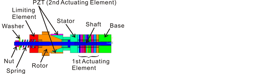
Figure 2. The cutaway view of the multiple composite piezoelectric motor.

Figure 3. The exploded view of the multiple composite piezoelectric motor.
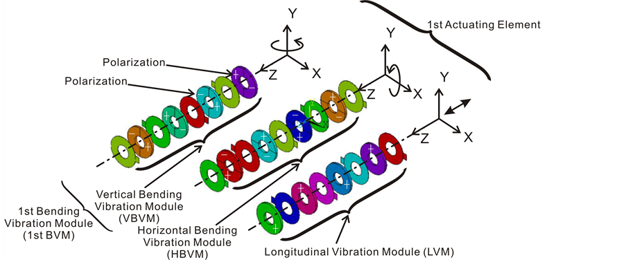
Figure 4. The operation principle of the 1st actuating element (Which it includes the Longitudinal Vibration Module_LVM and 1st Bending Vibration Module_1st BVM).

Figure 5. The operation principle of the 2nd actuating element (So called the 2nd Bending Vibration Module_2nd BVM).
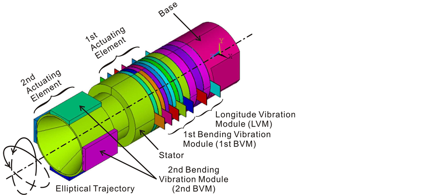
Figure 6. The operation principle of the multiple composite piezoelectric stator.

Figure 7. The operation principle of the multiple composite piezoelectric motor.
Where
 . (2)
. (2)
 . (3)
. (3)
 . (4)
. (4)
And
 . (5)
. (5)
 . (6)
. (6)
 . (7)
. (7)
where u, v, and w represents the vibration displacement of the horizontal, vertical and longitudinal direction separately. And where Um, Vm and Wm represents the vibration amplitude in different direction separately.  represents driving angle velocity, where fm representatives driving frequency. And
  driving phase angle (such as 0˚ - 180˚). Where cxi, cyi and czi represents the constant coefficient tensor in different direction separately, and where the subscript i = 1, 2, 3. d3i represents constant piezoelectric strain of d-form. Such as d31, d32 and d33.
3. Simulation and Experiment
We choose five different sizes of the multiple composite piezoelectric motors or stators to simulate by convention in order to compare with the previous papers [1] -[33] or [31] [33] , shown as Figures 8-9 and Table2 Wherein the base and stator is made of copper and aluminum separately. Which the first actuating element is made of PZT and copper slices. And the second actuating element is directly attached to the side of the stator by the PZT under different polarization direction, shown as Figure 6. As for the physical properties of the multiple composite piezoelectric stator is expressed in Table3
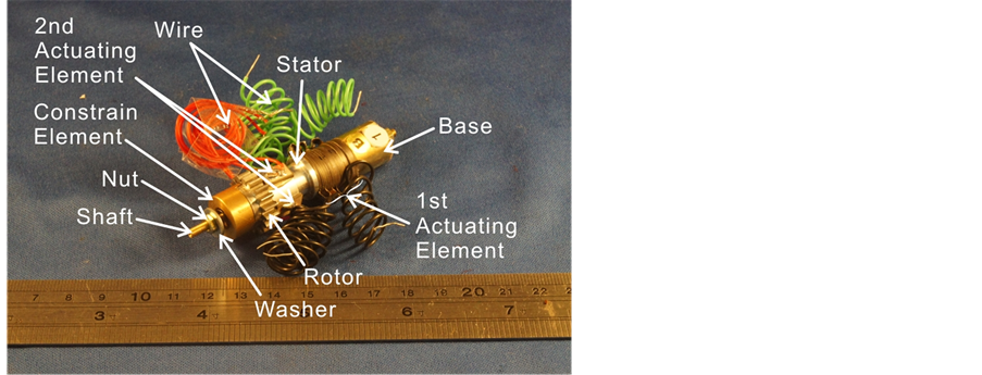
Figure 8. The prototype of the multiple composite piezoelectric motor.
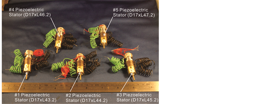
Figure 9. The prototype of the #1 - #5 multiple composite piezoelectric stators.

Table 2. The net weight and size of multiple composite piezoelectric stator.
Table 3. The physical properties of multiple composite piezoelectric stator.
We use the ANSYS code to simulate in this study. And the simulation procedure includes modeling (show as Figure 10), meshing (show as Figure 11), solving and post-processing. We choose the element type of solid 98 for all materials in modeling operation process. We choose the number 6 - 10 of smart size for all materials in meshing operation process. The mechanical boundary condition is set to clamped-free. As regards the electrical boundary conditions is set to open circuit (That is Vin = 0 or Vp-p = 0.) and closed circuit (That is Vin = 100 - 180 Vp-p or Vp-p = 100 - 180 Vp-p) for all piezoelectric materials in solving operation process.
In this experiment, we used two sets of the dual channel arbitrary function generator (Model: A-303, AA Lab. Systems Ltd. Co.) and four sets of the power amplifier (Model: AFG-3022, Tektronix Co.) to control or drive the multiple composite piezoelectric motor. In addition, we used the digital tachometer (Model: RM-1501, TES Electrical Electronic Co.) and the sound level meter (Model: TES 1350A, TES Electrical Electronic Co.) to measure the rotational speed and noise of the multiple composite piezoelectric motor separately. Furthermore, we are using the mass or rotor with two different materials to test the loading ability of the multiple composite piezoelectric motor, shown as Figure 12.
4. Results and Discussion
According to the results of simulations by the ANSYS code and experiments, we found:
1) The resonance frequency is inversely proportional to the length of the multiple composite piezoelectric stator. Wherein the first resonance mode frequency is 9.174 kHz of the #1 multiple composite piezoelectric stator. And the first resonance mode frequency is 7.565 kHz of the #5 multiple composite piezoelectric stator, shown as Figure 13.
2) The maximum deformation is inversely proportional to the length of the multiple composite piezoelectric stator. The maximum deformation and best vibration modes which appear in 38 - 39 kHz or the seventh vibration mode for the #1 - #5 multiple composite piezoelectric stator, shown as Figures 14-19.
3) The maximum rotational speed is inversely proportional to the length of the multiple composite piezoelectric motor. The #1 multiple composite piezoelectric motor has a maximum rotational speed of 600 rmp under conditions of 180 V-p- driving voltage, 37.8 kHz driving or resonance frequency, 00 driving phase angle and 12.1 gw loading. It is 1.25 and 3.0 times of the maximum rotational speed for the rod type ultrasonic motor [31] and the composite type piezoelectric motor [33] , shown as Figure 20.
4) The noise range is between 60 and 100 dB of the multiple composite piezoelectric motor, where the higher noise appears before 20 kHz. And the noise values are independent of the driving frequency, shown as Figure 21.
5) The conversion efficiency of direction of the multiple composite piezoelectric motor is inversely proportional to the length of stator. Wherein the best conversion efficiency of direction is the #1 multiple composite
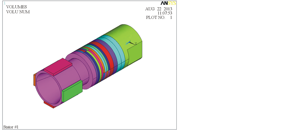
Figure 10. The modeling operation process of the #1 multiple composite piezoelectric stator in the simulation procedure.
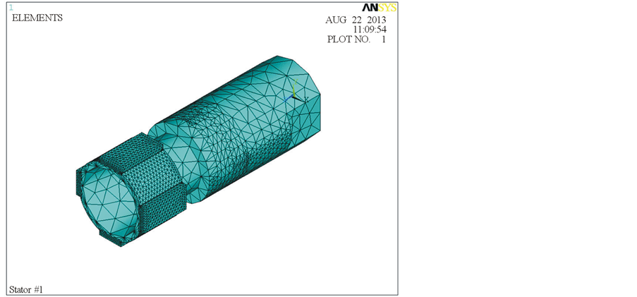
Figure 11. The meshing operation process of the #1 multiple composite piezoelectric stator in the simulation procedure.
piezoelectric motor. In addition, we also the poor conversion efficiency of direction is the rod type ultrasonic motor [31] , shown as Figure 22.
6) The rotational speed of the multiple composite piezoelectric motor is proportional to the driving voltage. On average, the rotational speed of the multiple composite piezoelectric motor is higher than the rod type ultrasonic motor and the composite type piezoelectric motor, shown as Figure 23. Moreover, according to the experimental results shown in Figure 23, we can find a linear relationship between rotational speed and driving voltage. As:
 (8)
(8)
where x, y represents the driving voltage and rotational speed respectively. In addition, the constants of ai, bi represent the slope and intercept of different type piezoelectric motors, shown as Table4
7) And rotational speed of the multiple composite piezoelectric motor is inversely proportional to the loading ability under the same driving conditions. Which has a maximum loading ability is the #1 multiple composite piezoelectric motor which is 2500 gw, shown as Figure 24. Where the loading ability of the multiple composite piezoelectric motor is 1.68 and 1.08 times of the maximum rotational speed for the rod type ultrasonic motor and the composite type piezoelectric motor.
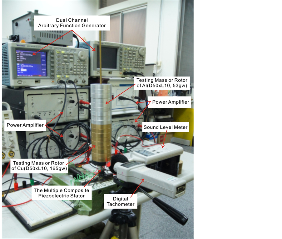
Figure 12. The experimental structure of the multiple composite piezoelectric stator.
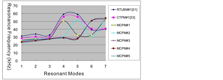
Figure 13. The driving frequency relative to the resonant modes of the #1 - #5 multiple composite piezoelectric stator.
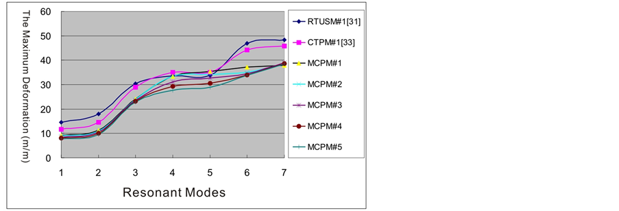
Figure 14. The maximum deformation relative to the resonant modes of the #1 - #5 multiple composite piezoelectric stator.
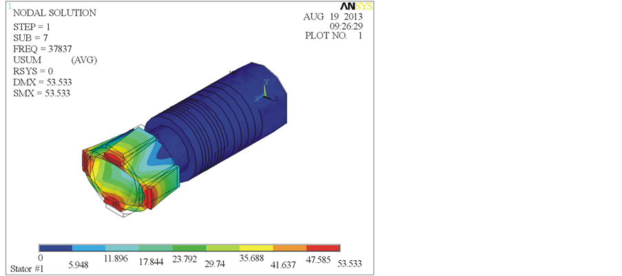
Figure 15. The best vibration mode of the #1 multiple composite piezoelectric stator.
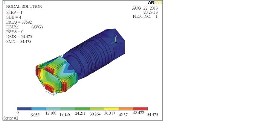
Figure 16. The best vibration mode of the #2 multiple composite piezoelectric stator.
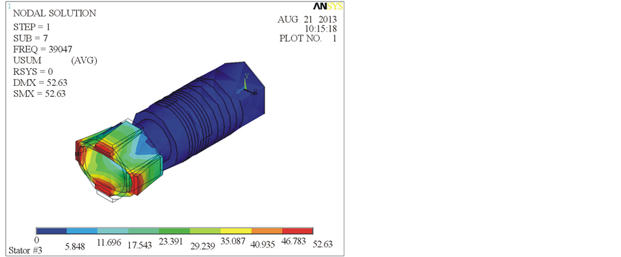
Figure 17. The best vibration mode of the #3 multiple composite piezoelectric stator.
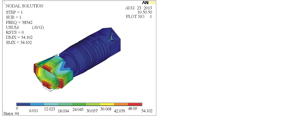
Figure 18. The best vibration mode of the #4 multiple composite piezoelectric stator.

Figure 19. The best vibration mode of the #5 multiple composite piezoelectric stator.

Figure 20. The rotational speed of different type motors relative to the driving frequency under conditions of 180 Vp-p driving voltage and 12.1 gw loading.
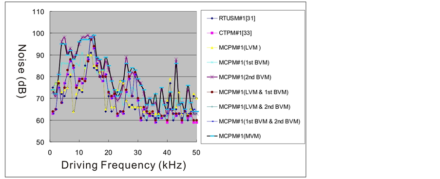
Figure 21. The noise of different type motors relative to the driving frequency under conditions of 180 Vp-p driving voltage and 12.1 gw loading.
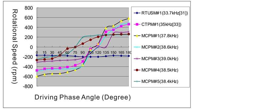
Figure 22. The rotational speed of different type motors relative to the driving phase angle under conditions of 180 Vp-p driving voltage and 12.1 gw loading.
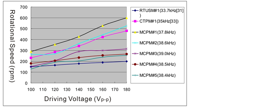
Figure 23. The rotational speed of different type motors relative to the driving voltage under conditions of 180 Vp-p driving voltage and 12.1 gw loading.
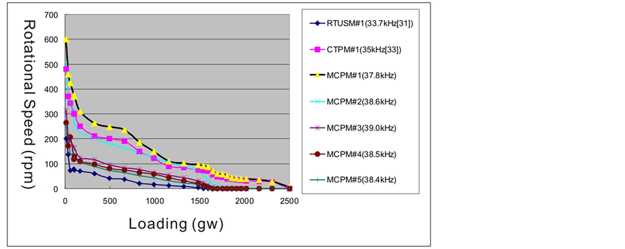
Figure 24. The rotational speed of different type motors relative to the loading under condition of 180 Vp-p driving voltage.
Table 4. The slope and intercept of different type piezoelectric motors.
5. Conclusion
In this study, we found that the multiple composite piezoelectric motor has better rotational speed, conversion efficiency of direction and loading ability relate to the previous similar type’s motor under the same driving conditions. The most special, when we use the multiple vibration modes to drive the motor, so that the above functions and efficiency achieve significant improvement and upgrade. Especially the maximum rotational speed of the multiple composite piezoelectric motor is 1.25 and 3.0 times of the composite type piezoelectric motor and the rod type ultrasonic motor respectively. Furthermore, the maximum loading ability of the multiple composite piezoelectric motor is 1.08 and 1.68 times of the composite type piezoelectric motor and the rod type ultrasonic motor respectively under conditions of the same driving voltage and loading or preload.
References
- Ohnishi, O., Myohga, O., Uchikawa, T., Tamegai, M., Inoue, T. and Takahashi, S. (1989) Piezoelectric Ultrasonic Motor Using Longitudinal-Torsional Composite Vibration of a Cylindrical Resonator. IEEE 1989 Ultrasonics Symposium Proceedings, 2, 739-743. http://dx.doi.org/10.1109/ULTSYM.1989.67085
- Takeoka, A., Ishikawa, A., Suzuki, M., Niki, K. and Kuwano, Y. (1989) Meissner Motor Using High-Tc Ceramic Superconductors. IEEE Transactions on Magnetics, 25, 2511-2514.
- Ohnishi, O., Myohga, O., Uchikawa, T., Tamegai, M., Inoue, T. and Takahashi, S. (1993) Piezoelectric Ultrasonic Motor Using Longitudinal-Torsional Composite Resonance Vibration. IEEE Ultrasonics, Ferroelectrics, and Frequency Control, 40, 687-693.
- Kawasaki, O., Nishikura, T., Sumihara, M., Ohtsuchi, T., Takeda, K., Nojima, T. and Imada, K. (1993) A Small Size Ultrasonic Motor. Systems, Man and Cybernetics, 1993. “Systems Engineering in the Service of Humans”, Conference Proceedings, International Conference, 1, 435-440.
- Shigeki, T., Shigeru, S., Zhang, G.Q., Yasutaro, M. and Kazuto, N. (1994) Multi Degree of Freedom Spherical Ultrasonic Motor. Industrial Electronics, Control and Instrumentation, IECON '94., 20th International Conference, 2, 900-905.
- Toyama, S., Sugitani, S., Zhang, G.Q., Miyatani, Y. and Nakamura, K. (1995) Multi Degree of Freedom Spherical Ultrasonic Motor. Robotics and Automation, 1 Proceedings, 1995 IEEE International Conference, 3, 2935-2940.
- Kurosawa, M., Takahashi, M. and Higuchi, T. (1996) Ultrasonic Linear Motor Using Surface Acoustic Waves. IEEE Ultrasonics, Ferroelectrics, and Frequency Control, 43, 901-906.
- Morita, T., Kurosawa, M. and Higuchi, T. (1997) A Cylindrical Micro Ultrasonic Motor Fabricated by Improved Hydrothermal Method. Solid State Sensors and Actuators, TRANSDUCERS '97 Chicago, International Conference, 1, 49-52.
- Wakai, T., Kurosawa, M.K. and Higuchi, T. (1998) Transducer for an Ultrasonic Linear Motor with Flexible Driving Part. Ultrasonics Symposium, Proceedings, 1998 IEEE, 1, 683-686.
- Li, C.D. and Zhao, C.S. (1998) A Large Thrust Linear Ultrasonic Motor Using Longitudinal and Flexural Modes of Rod-Shaped Transducer. Ultrasonics Symposium, 1998. Proceedings, IEEE, 1, 691-694.
- Takemura, K. and Maeno, T. (2000) Characteristics of an Ultrasonic Motor Capable of Generating a Multi-Degrees of Freedom Motion. Robotics and Automation, Proceedings, ICRA '00. IEEE International Conference, 4, 3660-3665.
- Nakamura, Y., Kurosawa, M.K., Shigematsu, T. and Asai, K. (2003) Effects of Ceramic Thin Film Coating on Friction Surfaces for Surface Acoustic Wave Linear Motor. Ultrasonics, 2003 IEEE Symposium, 2, 1766-1769. http://dx.doi.org/10.1109/ULTSYM.2003.1293254
- Guo, J.F., Gong, S.J., Guo, H.X., Liu, X. and Ji, K.H. (2004) Force Transfer Model and Characteristics of Hybrid Transducer Type Ultrasonic Motors. IEEE Ultrasonics, Ferroelectrics, and Frequency Control, 52, 387-395.
- Leinvuo, J.T., Wilson, S.A., Whatmore, R.W. and Cain, M.G. (2006) Flextensional Ultrasonic Piezoelectric Micro-Motor. IEEE Ultrasonics, Ferroelectrics, and Frequency Control, 53, 2357-2366.
- Shi, S.J., Chen, W.S. and Liu, J.K. (2006) A High Speed Ultrasonic Linear Motor Using Longitudinal and Bending Multimode Bolt-Clamped Langevin Type Transducer. Mechatronics and Automation, Proceedings of the 2006 IEEE International Conference, 612-617.
- Luo, L.H., Zhu, H., Zhao, C.S., Wang, H.X. and Luo, H.S. (2007) Cylinder-Shaped Ultrasonic Motors 4.8 mm in Diameter Using Electroactive Piezoelectric Materials. Applied Physics Letters, 90, 052904-052904-3.
- Kobayashi, A., Kanda, T. and Suzumori, K. (2007) Driving Performance of a Cylindrical Micro Ultrasonic Motor. Intelligent Robots and Systems, 2007. IROS 2007. IEEE/RSJ International Conference, 3809-3814.
- Ichihara, T., Kanda, T. and Suzumori, K. (2008) Design and Evaluation of Low-Profile Micro Ultrasonic Motors Using Sector Shaped Piezoelectric Vibrators. Intelligent Robots and Systems, IROS 2008. IEEE/RSJ International Conference, 588-593.
- Wajchman, D., Kuang-Chen Liu, Friend, J. and Yeo, L. (2008) An Ultrasonic Piezoelectric Motor Utilizing Axial-Torsional Coupling in a Pretwisted Non-Circular Cross-Sectioned Prismatic Beam. IEEE Ultrasonics, Ferroelectrics, and Frequency Control, 832-840.
- Yao, Z.Y., Yang, D., Wu, X. and Zhao, C.S. (2008) Structure Design Method of Bar-Structure Linear Ultrasonic Motors. Ultrasonics Symposium, IUS 2008. IEEE, 639-642.
- Sheng, M.W., Chen, W.S., Liu, J.K. and Shi, S.J. (2009) Study and Test of a Double-Rotor Ultrasonic Motor with Symmetrical Longitudinal-Torsional Converter. Applications of Ferroelectrics, ISAF 2009. 18th IEEE International Symposium, 1-4.
- Chu, X.-C., Chen, X.-Y. and Li, L.-T. (2009) A Miniature Disk-Pivot Piezoelectric Motor with Double Rotors. Piezoelectricity, Acoustic Waves, and Device Applications (SPAWDA) and 2009 China Symposium on Frequency Control Technology, Joint Conference of the 2009 Symposium, 107.
- Chen, P.-H., Wang, Y. and Huang, W.-Q. (2009) Design of a New Type of Piezoelectric Linear Motor Base on Non-Resonant Vibration. Piezoelectricity, Acoustic Waves, and Device Applications (SPAWDA) and 2009 China Symposium on Frequency Control Technology, Joint Conference of the 2009 Symposium, 105.
- Kondo, S., Koyama, D. and Nakamura, K. (2010) Miniaturization of the Traveling Wave Ultrasonic Linear Motor Using Bimorph Transducers. Ultrasonics Symposium (IUS), 2010 IEEE, 1482-1485.
- Wang, Y., Jin, J.M. and Huang, W.Q. (2010) A Compact Ultrasonic Motor Using Two in Plane Modes. Piezoelectricity, Acoustic Waves and Device Applications (SPAWDA), 2010 Symposium, 171-174.
- Qi, Z., Liang, P., Ting, M., Rang, K. and Hua, F. (2011) Piezoelectric Rotary Motor Based on Active Bulk Torsional Element With Grooved Helical Electrodes. Mechatronics, IEEE/ASME.
- Liu, Y., Liu, J. and Chen, W. (2011) A Cylindrical Traveling Wave Ultrasonic Motor Using a Circumferential Composite Transducer. Ultrasonics, Ferroelectrics and Frequency Control, 58, 2397-2404.
- He, S.Y., Chiarot, P.R. and Park, S. (2011) A Single Vibration Mode Tubular Piezoelectric Ultrasonic Motor. IEEE Ultrasonics, Ferroelectrics, and Frequency Control, 58, 1049-1061.
- Liu, Y.X., Chen, W.S., Liu, J.K. and Shi, S.J. (2011) A High-Power Linear Ultrasonic Motor Using Longitudinal Vibration Transducers with Single Foot. Ultrasonics, Ferroelectrics and Frequency Control, 57, 1860-1867.
- Jou, J.-M. (2011) A Study on the Multi-Block Piezoelectric Car. 2011 International Symposium on Mechatronic and Biomedical Engineering & Applications, 123-128.
- Jou, J.-M. (2013) A Study on the Rod Type Ultrasonic Motor. Advanced Materials Research, 716, 600-607.
- Jou, J.-M. (2013) A Study on the Piezoelectric Motor of High Actuating Force. Life Science Journal, 10, 242-248.
- Jou, J.-M. (2013) A Study on the Composite Type Piezoelectric Motor. Open Journal of Acoustics, 3, 88-95. http://dx.doi.org/10.4236/oja.2013.33014
Notes
RTUSM: Rod Type Ultrasonic Motor.
CTPM: Composite Type Piezoelectric Motor.
MCPM: Multiple Composite Piezoelectric Motor.
LVM: Longitudinal Vibration Module or Mode.
1st BVM: the first Bending Vibration Module or Mode.
2nd BVM: the second Bending Vibration Module or Mode.
MVM: Multiple Vibration Module or Mode.